Transcription
SURGICALMANUALGRAND MORSE
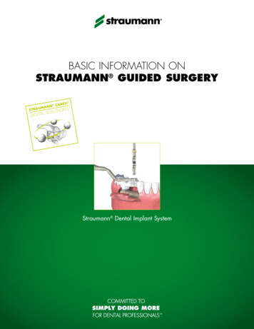
THE GRAND MORSE IMPLANT SYSTEM
CONTENTS1.0 BASIC INFORMATION ON SURGICAL PROCEDURES82.0 NEODENT IMPLANT SYSTEM82.1 Overview3.0 IMPLANT DESIGNS3.1 Surface811123.1.1 NeoPoros123.1.2 Acqua133.2 Implant Options143.2.1 Helix GM143.2.2 Drive GM 143.2.3 Titamax GM 153.3 Options for Screw Threads and Overview of the Format According toImplant Design164.0 INDICATIONS AND CONTRAINDICATIONS185.0 PREOPERATIVE PLANNING195.1 Implant positioning and peri-implant tissue5.1.1 Mesiodistal positioning of the implant19205.1.1.1 Examples of single tooth gaps215.1.1.2 Examples of multiple tooth gaps225.1.2 Vestibulolingual implant position245.1.3 Cervicoapical position of the implant245.2 Planning Aids5.2.1 Space Planning Instrument for assisting in the diagnosis and positioning of implants25255
5.2.2 Direction indicators for diagnosing the adjacent bone265.2.3 Surgical drill guide286.0 SURGICAL PROCEDURES6.1 Implant bed preparation6.1.1 Basic implant bed preparation2929296.1.1.1 Implant bed preparation for Helix GM conical implants316.1.1.2 Implant bed preparation for Drive GM conical implants346.1.1.3 Implant bed preparation for Titamax GM cylindrical implants356.1.2 Details on special implant bed preparation376.1.2.1 Tapered Contour Drill376.1.2.1 Pilot Drill386.1.2.3 Example of special implant bed preparation386.1.2.4 Options for drills406.2 Neodent Implant Packaging406.3 Placing of the Grand Morse Implant426.3.1 Placing of the implant with the contra-angle handpiece426.3.2 Manual placement of the implant446.3.3 Completing the positioning of the implant with the Torque Wrench446.3.4 Torque Wrench456.4 Handling soft tissue456.4.1 Two-step/submucosal healing456.4.2 Transmucosal healing: one-step or immediate loading496.4.2.1 Transmucosal healing: one-step506
6.5 Overview of the healing abutments516.5.1 Overview of Grand Morse abutments and corresponding healing abutments526.5.1 Grand Morse Customizable Healing Abutments537.0 HEALING PHASE548.0 GENERAL PROSTHETIC GUIDELINES549.0 NEODENT KITS559.1 Cleaning and Care of the Cassette and Instruments559.2 Sterilization of the Cassette and Instruments559.3 Cleaning and Care of the Drills569.4 Drill Sterilization57BIBLIOGRAPHY597
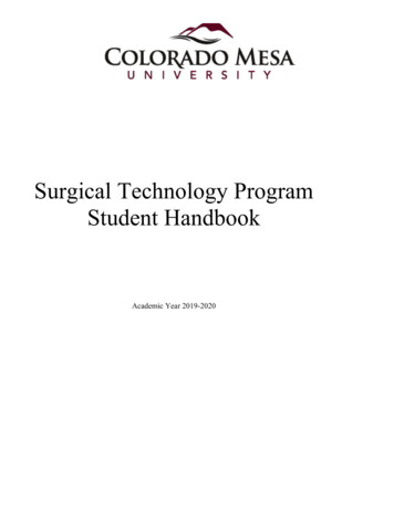
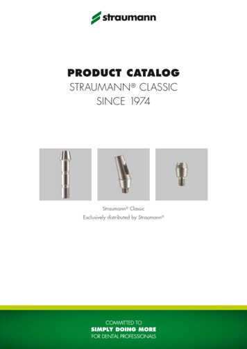
1.0 BASIC INFORMATION ON SURGICAL PROCEDURESThe modern era of implant dentistry, based on the clinical results of osseointegration, was originallypublished in English journals in 19771. Since then, dentistry has undergone significant changes. The currenttreatment plan for patients usually offers implant-retained and/or implant-supported prostheses as anaccessible and reliable solution. The number of dental implants has increased rapidly in recent years,2,3and this form of treatment requires specific knowledge and skills, such as the surgeon’s learning curve,which are relevant to the results.4 Based on these facts, the objective of these guidelines is to providedental surgeons and specialists with basic information and guidelines on planning, surgical proceduresand treatment options.These guidelines do not substitute each product’s instructions for use (IFU). These can be foundat our website: www.ifu.neodent.com.br. It is the surgeon’s sole responsibility to analyze the patients’general health, the viability of the surgical procedure and the most appropriate products for each clinicalsituation.2.0 NEODENT IMPLANT SYSTEM2.1 OverviewNeodent ’s Grand Morse (GM) Implant System offers various design options for implants, screwthreads, and apex, as well as two types of surface treatment. Neodent ’s philosophy is to offer an implantsolution suited to each specific indication, including bone density and quantity and surgical technique. Allimplants can be placed with the Grand Morse Surgical Kit. The procedures are standardized and havesequential steps.Bone type I, II,Bone typeBone typeIII and IVIII and IVI and IIFIGURE 1 – Options for Neodent implants according to their indication.8
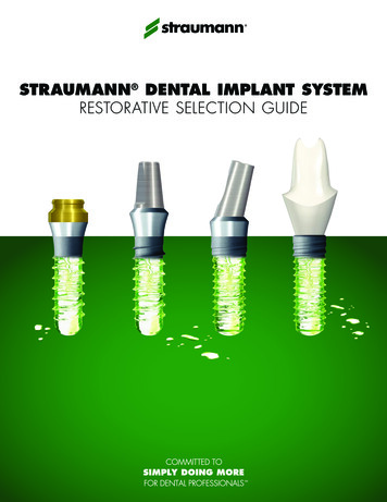
All Grand Morse implants (Helix GM, Drive GM and Titamax GM ) have the same size prostheticconnection, regardless of the implant’s diameter (Figure 2), with an internal angle of 16 . The implant’sthicker inner walls give it greater mechanical resistance and superior results when compared with variousinternal connections5,6 and have been strategically designed for the Grand Morse portfolio.FIGURE 2. The connection of the Neodent Grand Morse implant has the same width, regardless of the implant’s diameter.3.0 mm16 3.7 mmFIGURE 3. Neodent ’s Grand Morse implant features a deep connection in its interior, designed to increase the contactarea between the implant and the prosthetic abutment.9
The Grand Morse conical connection features an internal hexagon index in the lower portion calledthe GM Exact. GM Exact is used to surgically position the implant and reposition prosthetic abutments whenworking at implant level.FIGURE 4. Internal hexagon index, createdto surgically guide the implant and mold theimplant during the prosthetic phase.The system has a complete portfolio, adapted to the patient’s bone density and quality.Diameter (mm)Implant3.53.754.04.35.06.0Helix GMDrive GM Titamax GM TABLE 1. Available diameters according to implant design.10
LengthImplant789101111.5 121314151617*Helix GM18*Drive GM Titamax GM TABLE 2. Available lengths according to implant design.*Helix Ø 6.0 mm is not available in lengths 16 or 18 mm.3.0 IMPLANT DESIGNSNeodent ’s Grand Morse implants are classified according to their macrostructure, screw acteristics, apex and x Titamax Drive FIGURE 7. General features of Neodent Grand Morse implants.11
3.1 SurfaceNeodent implants are available in two types of surface treatment, as shown below. The decisionregarding each surface should be guided by the clinical indication.3.1.1 NeoPorosNeoPoros is a process specially created for the surface of Neodent implants. First, roughness isobtained by means of sandblasting, in which the particle size and pressure are adjusted to the implantdesign. After sandblasting, the implant undergoes an acid etching process under specific conditions.Figure 8 shows this procedure.MachinedSa 0.26 μmSandblastingSa 0.67 µmSandblasting Acid etchingSa 0.93 µmFIGURE 8. Physical manufacturing process for the Neodent surface treatment.FIGURE 9. Micro (0.3 - 1.3 μm) and macro (15 - 30 μm)roughness for Acqua and NeoPoros.FIGURE 10. Confocal laser scanning microscopy inthe screw thread region.1512
3.1.2 AcquaAcqua is a hydrophilic implant with surface-modified titanium. The physical process of theNeoPoros surface is performed on the Acqua implants; however, the Acqua surface is obtained in aspecial area of the production center where all the implants are packaged and stocked in liquid thuspreventing contact with the atmosphere. This isolation results in wettability (presenting a contact angle 5 ) and a polarised surface with positive ions15.The hydrophilic surface (Figure 9) presents a smaller contact angle when in contact with organicfluids. This provides them greater accessibility of blood to the implant surface15. Implants with the Acquasurface are indicated for implantation in grafted areas, in combination with bone graft procedures, postextraction placement and sites with low bone density.17,18Comparison between SurfacesNeoPoros SurfaceAcqua Hydrophilic SurfaceFIGURE 11. Comparison between NeoPoros surface and the Acqua hydrophilic surface.Note: Chemical composition analysis of the Acqua and NeoPoros surfacesusing the XPS methodNeoPoros (Atom %)Acqua (Atom %)Oxygen O55.9 0.959.3 0.2Titanium Ti21.1 0.722.7 0.3Nitrogen N0.4 0.60.6 0.4Carbon C22.7 2.015.3 1.013
3.2 Implant Options3.2.1 Helix GM(1) Available in the Acqua or NeoPoros surface; (2) Fully tapered implant;(3) Compacting trapezoidal screw threads with a thread pitch from 1.2 to 1.5 mm(depending on the implant diameter); (4) Implant with dual screw threads for minimaltrauma and faster placement19; (5) Conical apex with low-activity chambers and helicalchambers designed to optimize secondary stability; (6) Indicated for all bone densitytypes and post-extraction placement; (7) Tapered contour drill is required if used inbone types I and II; (8) Same prosthetic connection for all implant diameters; (9) Finalpilot drills highly recommended for bone types I and II; (10) The implant should bepositioned 1-2 mm below bone level for best results19; (11) Drilling speed: 800-1200rpm for bone types I and II; (12) Drilling speed: 500-800 rpm for bone types III and IV;(13) Insertion speed: 30 rpm; (14) Maximum insertion torque: 60 N.cm.3.2.2 Drive GM (1) Available in Acqua or NeoPoros surface; (2) Fully tapered implant; (3) Mainscrew threads have a square format with a thread pitch of 2.2 mm; (4) Implant withdual thread for minimal trauma and faster placement19,20; (5) Counterclockwise cuttingchambers distributed throughout the implant body; (6) Lower portion of the screwthread with cutting edge; (7) Round apex; (8) Indicated for bone types III and IV andimmediate placement of a postextraction implant; (9) Same prosthetic connection forall implant diameters; (10) The implant should be positioned 1-2 mm below bone levelfor best results; (11) Drilling speed: 500 - 800 rpm; (12) Insertion speed: 30 rpm; (13)Maximum insertion torque: 60 N.cm.14
3.2.3 Titamax GM (1) Available in Acqua or NeoPoros surface; (2) Implant with parallel walls(cylindrical); (3) Triangular (or pyramidal) screw threads with a thread pitch of 1.2mm; (4) Implant with dual screw thread for minimal trauma and faster placement19;(5) Active cutting apex with self-tapping chambers; (6) Indicated for bone types I andII and block bone graft areas; (7) The implant’s cervical diameter is the same as thebody; (8) Final pilot drills are highly recommended as the implant should be positioned1-2 mm below bone level for best results19; (9) The use of tap drill is not necessary asthe implant itself cuts the bone during placement; (10) Drilling speed: 800 - 1200 rpm;(11) Insertion speed: 30 rpm; (12) Maximum insertion torque: 60 Ncm.Bone DensityBone type IIIBone type IVTitamax GM Acqua--Titamax GM --ImplantBone type IHelix GM AcquaHelix GMBone type II****Drive GM Acqua--Drive GM --TABLE 3. Summary of the implant indication according to bone type (Lekholm and Zarb, 1985).*Conical contour drill is required15
3.3 Options for Screw Threads and Overview of the Format According toImplant Design*There are variations due to the length and diameter options for the implant.Helix GM:0.60 - 0.75 mm0.15 - 0.55 mm16
Drive GM :1.10 mm0.40 - 0.71 mmTitamax GM :0.55 - 0.80 mm0.30 - 0.60 mm17
4.0 INDICATIONS AND CONTRAINDICATIONSNeodent implants are manufactured with cold-worked grade 4 titanium to increase the product’smechanical resistance. All posts and abutments are made of titanium alloy (TAV). The following table lists thespecific measurements for these items.ImplantMinimum width ofMinimum width of thealveolar ridge*gap**5.5 mm5.5 mm8/10/11.5/13/16***/18*** mmBone tissue with density III or IV,postextraction placement and inregions grafted with biomaterial.5.5 mm5.5 mm8/10/11.5/13/16/18 mmBone tissue with density typeI or II, placement in block graftarea.5.5 mm5.5 mm7/8/9/11/13/15/17 mmGeneral indicationAll clinical cases and differentbone densities. Placement inbone types III and IV (with thepossibility of subinstruments),I and II with use of a taperedcontour drill.Available lengthsHelix GMDrive GM Titamax GM *Minimum width of the alveolar ridge: minimum vestibulolingual width of the alveolar ridge, rounded to 0.5 mm.**Minimum width of the gap: minimum mesiodistal width of a single tooth gap restoration, between adjacent teeth, rounded to 0.5 mm.***Helix Ø 6.0 mm is not available in lengths 16 or 18 mm.For more information on indications and contraindications for each implant, consult the correspondinginstructions for use. The instructions can also be found at ifu.neodent.com.br.18
5.0 PREOPERATIVE PLANNING5.1 Implant positioning and peri-implant tissuePositioning the implant is the key for obtaining the correct positioning of the prosthetic restorationand is the basis for the surgical plan. Proper communication between the patient, surgeon, prosthetist anddental prosthesis technician is essential for achieving the desired prosthetic results.To establish the correct plan, with proper spatial positioning and design choice (diameter and length)and the correct number and distribution of implants, the following steps are recommended:-Perform the wax-up in the patient’s study model.-Define the edentulous gap to be restored.-Define the type of superstructure.-Perform computed tomography and radiography.The wax-up can be used to make the radiographic and/or surgical guide and as the provisionalrestoration. Physiological occlusion is essential for the short- and long-term success of the implant. Immediateloading procedures should not be performed on patients with occlusion problems.Notes: Prosthetic abutments should always receive axial loads, and the implant’s long axis should be aligned with the cusps ofthe opposing teeth. The extreme anatomy of the cusps should be avoided, because it can lead to pathological overload.The diameter, type, position and number of implants should be decided on an individual basis for eachpatient, taking into consideration the anatomy and prosthetic gap. Poorly positioned or angled teeth shouldbe considered and analyzed. The recommendations in these guidelines should be considered a basic guidefor proper biological healing, adequate restorations and for the patient to have efficient hygiene in that area.The design of the restoration has a strong effect on occlusion and hygiene and should be considered.The final response of soft and hard tissue is highly influenced by the position of the abutment;therefore, three-dimensional positioning of the implant needs to be studied and consists of the following: Mesiodistal Vestibulolingual Cervicoapical19
5.1.1 Mesiodistal positioning of the implantThe mesiodistally available bone is an important factor in choosing the diameter and number ofimplants. Mesiodistal gap is the distance between the implant and the teeth or between implants, whenmultiple implants are necessary. The point of reference is the measurement of the largest mesiodistalwidth of the implant, usually in the cervical regions. Implants generally require a minimum of adjacent bonesurrounding them of 1.5 mm. The distances listed here are rounded to a minimum of 0.5 mm of bone.However, in preclinical studies, Cone Morse implants placed below bone level present bone and soft tissuemaintenance up to an interimplant distance of 2.0 mm.9The basic rules are as follows:Rule 1Ideally, the distance from the implant to theadjacent teeth should be at least 1.5 mmbetween the largest portion of the implantand the teeth, in both the mesial and distalaspects.Rule 2Given that the implants require a minimumadjacent bone of 1.5 mm, the minimumdistance to other implants is 3.0 mm.20
5.1.1.1 Examples of single tooth gapsFor single tooth restorations, the implant should be placed in the center of the gap. The followingexample shows how to follow Rule 1.For all Neodent Grand Morse implants, the gap size needs to be considered when selecting theimplant diameter. To position an implant within the gap according to Rule 1, the following aspects may be usedas an approximation:0.5 mm for bothDistance at the bone levelbetween adjacent teethFIGURE 12. The distance between adjacent teeth is approximately 1.0 mm greater at the bone level due to the dentalanatomy and the interproximal contact point, when compared with the actual bone width of the gap (2 x 0.5 mm).Therefore, applying Rule 1, the gap must be 2.0 mm wider than the width of the implant.21
D - Diameter ofthe Implant (mm)B - Distance betweenA - Width of the Gap (mm) the adjacent teeth at thebone level .06.08.09.0RuleD 2 mmD 3 mm*E1 - Toothimplant distance(mm)1.5*Rule 1 applied on both sides of the implant.5.1.1.2 Examples of multiple tooth gapsThe examples below show how Rules 1 and 2 are applied to multiple tooth gaps. The measurementsare performed in the bone crest of the tooth adjacent to the center of the implant and between the centersof the implants. The center of the implant should be considered due to the initial drilling during the osteotomy.The minimum distance of 3 mm should be followed between the cervical regions of the implants (Rule 2),which is important for flap closure, to avoid proximity of the abutments and provide adequate space formaintenance, emergency restoration profile and oral hygiene.22
D1 - Diameter of the D2 - Diameter of theImplant (mm)Implant .06.04.59.04.518E1 - Toothimplantdistance (mm)1.5E2 - ImplantimplantDistance (mm)3.0Normally, clinical cases have different gaps andconsequently D1/D2 can be different. The implants shouldtherefore be adapted for each situation. In search of a simplerrule, the dentist should consider that each implant requires aminimum of 1.5 mm of adjacent bone, regardless of the implant’sdiameter. Therefore, during planning, we need to remember thatregardless of the implant diameter, it is important to have aminimum of 1.5 mm of mesial and distal peri-implantation bone.1.5 mm23
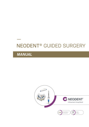
5.1.2 Vestibulolingual implant positionThe buccal and palatal bone plate should be at least 1 mm thick to ensure the stability of the bonetissue and the condition of the soft tissue. The minimum vestibulolingual width for each implant diameter islisted in Table 4. Within this limitation, the vestibulolingual position and the long axis of the implant should bechosen to provide the best possible restorative results. The surgeon also needs to know whether the plan isto place a screw-retained or cement-retained prosthesis.Warning: Bone graft techniques are highly advisable in the alveolar ridges in which the buccal bone plate is 1 mmthick or less or when bone is lacking on one of the sides. These procedures should be conducted only by surgeons withadvanced experience in bone regeneration with grafts.(A)(B)FIGURE 13. Example of implant positioned for cement-retained prosthesis (A) and screw-retained prosthesis (B),where there is access to the retaining screw.5.1.3 Cervicoapical position of the implantNeodent Grand Morse implants weredeveloped for 2-mm positioning below bone levelto optimize the stability of hard and soft tissueand for better esthetic results of the restorations,especially in the anterior regions.6,7,8,9,10,12For situations with uneven ridges, positionthe implant at the bone level corresponding to themost apical bone wall. Depending on the clinicalcase, some osteotomy might be required, given thatthe abutments have limitations in the transmucosalheight. The implant should be completely coveredwith bone or graft with biomaterials to preventtitanium dehiscence.24
5.2 Planning Aids5.2.1 Space Planning Instrument for assisting in the diagnosis and positioning of implantsWhen using the 7/9 mm Space Planning Instrument in the patient’s mouth or in the study model, aninitial analysis of the spatial relationships can be performed, in order to select the implant diameter and theprosthetic reconstruction. The Space Planning Instrument has two ends measuring 7 and 9 mm in diameter,with a mark exactly in the middle of each end (3.5 and 4.5 mm); this acts as a reference for the surgeon toposition the implant, respecting the rule of a 1.5-mm minimum adjacent peri-implant bone thickness.FIGURE 14. DiagnosticSpace Planning Instrumentfor gaps and positioningof implants.FIGURE 15. Close-up of the7-mm end of the SpacePLanning Instrument foranalyzing the gaps. The markis 3.5 mm from the edge.The 1.5-mm rule is important for placing the implant based on the position of the teeth, implants andanatomical structures, such as nerves. The Space Planning Instrument can help with the positioning of animplant close to a foramen.FIGURE 16. Using the Space Planning Instrument for the positioning of the osteotomy for implant placement.25
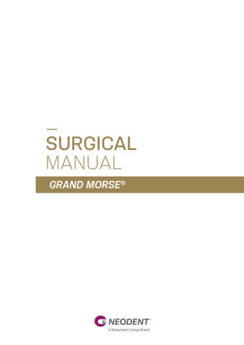
5.2.2 Direction indicators for diagnosing the adjacent boneAll Neodent Direction Indicators have different designs for analyzing the amount of bone surroundingthe osteotomy. All indicators have the following parts: (1) lower, (2) middle and (3) upper.LowerMiddleUpperFIGURE 17. The lower (2 mm), middle (diameter of the implant) and upper (diameter of the last drill used in the basicosteotomy) parts of the Direction Indicator.The lower part of all Direction Indicators is 2.0 mm in diameter, to be adjusted after the initial osteotomy.The middle part of the Direction Indicator has the diameter of the respective implant. All diameters are colorcoded and are listed in Table 4.DiameterDirection .3TABLE 4. Options for Colored Direction Indicators. The center part of the direction indicator has the same width as the implants, based onthe measurements marked on the upper part.26
The upper part of each direction indicator has the same diameter as the last drill used before theplacement of the implant, according to the Neodent osteotomy protocols. The positioned Direction Indicatorallows the surgeon to check the adjacent bone, as illustrated below.3.753.0FIGURE 18. Direction Indicator inserted after the initial drilling and fitted inside the osteotomyaccording to the drill protocol. The indicator helps analyze the remaining adjacent bone whenpositioned.There are also Angle Measurement guides that help the surgeon assess the angulation of abutmentsbefore the implant placement. These measurement guides are available in two angles (17 and 30 ) and areinserted in the 2.0-mm osteotomy.FIGURE 19. Angle measurement guides for selectingabutments.27
Notes: The Titanium Tweezers have a ruler at the apex.FIGURE 20. Titaniumtweezers calibrated inmillimeters.5.2.3 Surgical drill guideA customized surgical guide produced by the prosthesis laboratory facilitates the preparation of theimplant bed, enabling the precise use of cutting instruments. The basis for the manufacture of this guideshould be the desired prosthetic results.The study models can be drilled with 2.0-mm drills in the position of the implant, and guides for the2.0-mm diameter pins are fitted on the perforations. Guides manufactured with wax or vacuum-formed arebuilt with the pins positioned in their interior. Once the surgical guide has been made aseptic, it can be usedduring surgery, and its guides will direct the initial drilling of the surgical procedure.2.02.02.0FIGURE 21. 2.0-mm diameter guides and pins to be fitted in the patient’s study model.28
6.0 SURGICAL PROCEDURES6.1 Implant bed preparationThe diameter, position and number of implants should be selected based on the anatomy and spatialcircumstances. The measurements should be performed according to the basic guidelines.The basic preparation of the implant bed involves preparing the ridge and perforating with a twistdrill under irrigation, for which the diameter and design (if cylindrical or conical) of the selected implant willdetermine the instruments to be used.The refined implant bed preparation involves the instruments that conform to the emergence profileand the bone. For this, the implant type and bone density determine the instruments to be used.StepsInstruments1. Basic implant bed preparationPreparation of the ridgeTwist drillingInitial Drill2.0-mm twist drill; Direction Indicator;Depth Gauge with millimeter markings2. Refined implant bed preparationConical or cylindrical drills and bone profile drillsDrill format is defined according to the implant design, and thesequence and diameter defined by its widthTapered Contour DrillFor Helix GM in bone types I and IINote: The Titamax GM , Helix GM and Drive GM implants can be placed using the same surgical kit, given that Helix GMand Drive GM have conical drills for implant bed preparation and that Titamax GM also features specific drills.6.1.1. Basic implant bed preparationAfter opening the flap and exposing the bone tissue, the preparation of the alveolar ridge begins.Once the implant’s position has been established and with the aid of surgical guides, the cervical corticallayer is drilled with the Initial Drill (step 1), and the spatial positioning of the implant is checked visually. Theindicated number of rotations per minute (rpm) for drilling is based essentially on bone density, whereby 8001200 rpm will be applied in bone types I and II, and 500-800 rpm in bone types III and IV. Subsequently, the2.0-mm twist drill is used to establish the desired height for the selected implant, always keeping in mindthat the placement of the Grand Morse implant is 1-2 mm below bone level. Consequently, a subsequentdrill is employed to prepare the osteotomy, following the sequence based on the implant type and diameter,as chosen in the preoperative plan. All drills are fitted to the contra-angle handpiece according to ISO 17971 – Dentistry – Shanks for rotary instruments.29
Step 1 – Preparing the site of the implant and initial drillingwith the Initial DrillCarefully reduce and regularize the bone surface beforemarking the position of the implant with the initial needledrill. Insert the needle drill to approximately 5-7 mm with adrill speed consistent with the bone density.Note: Bone reduction/preparation should be considered in the preoperativeplan, because it affects the choice of implant diameter and length.Step 2 – Checking the long axis of the implantAfter using the initial drill, check the long axis of theimplant using the direction indicator. The implant diametersand measurements of adjacent bone can be checked asdescribed in 3.2.2.Step 3 – Twist Drill 2.0Use the 2.0-mm twist drill to reach the planned drillinglength. Use of the depth gauge is recommended forcontrolling the depth.Note: 1 – Periapical radiography is recommended at this point to checkfor available vertical bone or to verify the long axis of the drilling in relationto the adjacent roots, for example. The Direction Indicator should becompletely inserted into the instrumented area, allowing for visualizationof the entry of the drilling in relation to the anatomical structures.2 – The 2.0-mm Neodent twist drill has an active apex that can beused as an initial drill. For flat bony ridges, this drill can replace theinitial drill.30
6.1.1.1 Implant bed preparation for Helix GM conical implantsInitialØ 2.0Ø 3.5Ø 3.5 Ø 2.8/3.5Ø 3.75103.170103.425103.399103.419103.414103.402Ø 3.5OptionalØ 3.75OptionalØ 4.0OptionalØ 4.3OptionalØ 5.0OptionalØ 3.75 Ø 3.0/3.75103.420103.415Ø 4.0Ø 4.0 Ø 3.3/4.0Ø 4.3Ø 4.3 Ø 3.6/4.3Ø 5.0Ø 5.0 03.423Ø 4.3/5.0103.418Ø 6.0103.427OptionalBone types I and IIØ 3.5OptionalØ 3.75OptionalØ 4.0OptionalØ 4.3OptionalØ 5.0OptionalØ 6.0OptionalOptionalOptionalOptionalOptionalFor bone types III and IVNote: Periapical radiography is recommended after the use of conical drills to check for available bone or to verify the long axis ofthe drilling in relation to the adjacent roots. A radiographic positioner should be inserted in the instrumented area.31
Helix GM - For bone types I and IIInstruments for basic bone implant preparationStepCode1 – Prepare theimplant bed andinitial drilling103.170Initial Drill2 – Check the longaxis of the implant128.019Directionindicator 2.8/3.53-Taperd Drill 2.0*103.425Tapered Drill 2.01200103.419Tapered ContourDrill 3.51200103.399Tapered Drill 3.51200128.019Directionindicator 2.8/3.5-129.009Tapered X-RayPositioner 3.5-103.414Pilot Drill 2.8/3.51200103.420Tapered ContourDrill 3.751200103.402Tapered Drill 3.751200128.020Directionindicator 3.0/3.75103.415Pilot Drill 3.0/3.751200103.421Tapered ContourDrill 4.01200103.405Tapered Drill 4.01200128.021Directionindicator 3.3/4.0-103.416Pilot Drill 3.3/4.012004-Tapered 3.55-Pilot Drill2.8/3.56-Tapered 3.757-Pilot Drill3.0/3.758-Tapered 4.09-Pilot Drill3.3/4.0Max. RPM1200Ø 3.5 Ø 3.75 Ø 4.0 Ø 4.3 Ø ionalOptional---------------Tapered ContourDrill 4.31200103.408Tapered Drill 4.31200128.022Direction indicator3.6/4.3-129.013Tapered X-RayPositioner 4.3-103.417Pilot Drill 3.6/4.31200103.423Tapered ContourDrill 5.01200103.411Tapered Drill 5.01200128.023Directionindicator 4.3/5.0-129.014Tapered X-RayPositioner 5.0-13-Pilot Drill 4.3/5.0 103.418Pilot Drill 4.3/5.012-Tapered 5.0Image-103.42210-Tapered 4.311-Pilot Drill 3.6/4.3ProductDiameters (mm)-OptionalOptional---Optional--1200*The sequence can be started directly with the 2.0 drill if the bone bed is flat.32
Helix GM - For bone types III and IVInstruments for basic bone implant preparationStep1-Prepare theimplant bed andinitial drilling*Code103.1702-Check the long128.019axis of the implantProductInitial DrillMax. RPMDiameters (mm)ImageØ 3.5 Ø 3.75 Ø 4.0 Ø 4.3 Ø 5.0 Ø 6.0800Directionindicator ional------OptionalOptionalOptional-3-Tapered Drill 2.0* 103.425Tapered Drill 2.0800103.419Tapered ContourDrill 3.5800103.399Tapered Drill 3.5800128.019Directionindicator 2.8/3.5-129.009Tapered X-RayPositioner 3.5-103.414Pilot Drill 2.8/3.5800-----103.420Tapered ContourDrill 3.75800-----103.402 Tapered Drill 3.75800Optional-4-Tapered 3.55-Pilot Drill2.8/3.56-Tapered 3.75128.020Directionindicator 3.0/3.75----7-Pilot Drill 3.0/3.75 103.415 Pilot Drill 3.0/3.75800----103.421Tapered ContourDrill 4.0800----103.405Tapered Drill 4.0800Optional---128.021Directionindicator 3.3/4.0----800-----8-Tapered 4.09-Pilot Drill3.3/4.0103.416 Pilot Drill 3.3/4.0103.422Tapered ContourDrill 4.380
5.2.3 Surgical drill guide 28 6.0 SURGICAL PROCEDURES 29 6.1 Implant bed preparation 29 6.1.1 Basic implant bed preparation 29 6.1.1.1 Implant bed preparation for Helix GM conical implants 31 6.1.1.2 Implant bed preparation for Drive GM conical implants 34 6.1.1.3 Implan