Transcription
Data Acquisition and Processing ReportLeidos Doc 18-TR-011U.S. DEPARTMENT OF COMMERCENATIONAL OCEANIC AND ATMOSPHERIC ADMINISTRATIONNATIONAL OCEAN SERVICEData Acquisition & Processing ReportType of Survey Basic Hydrographic SurveyProject:OPR-K371-KR-17Time Frame: 16 September 2017 – 04 December 2017LOCALITYStateLouisianaGeneral LocalityNorthern Gulf of Mexico2017CHIEF OF PARTYAlex T. BernierLeidosLIBRARY & ARCHIVESDATEProject: OPR-K371-KR-1702/16/2018
Data Acquisition and Processing ReportLeidos Doc 18-TR-011Data Acquisition & Processing ReportOPR-K371-KR-17Leidos Document Number: 18-TR-011Changes in this document shall be recorded in the following table in accordanceISO9001:2015 Procedures.RevDate016 February 2018Project: OPR-K371-KR-17RevisionsPagesApproved ByAffectedAllA. BernieriRemarksInitial Document02/16/2018
Data Acquisition and Processing ReportLeidos Doc 18-TR-011Table of ContentsA.EQUIPMENT . 1A.1A.2A.3A.4A.5A.6A.7A.8A.9A.10B.PageDATA ACQUISITION . 1DATA PROCESSING. 1SURVEY VESSEL . 1LIDAR SYSTEMS AND OPERATIONS . 3MULTIBEAM SYSTEMS AND OPERATIONS . 3SIDE SCAN SONAR SYSTEMS AND OPERATIONS . 7SOUND SPEED PROFILES . 9BOTTOM CHARACTERISTICS . 11DATA ACQUISITION AND PROCESSING SOFTWARE . 12SHORELINE VERIFICATION . 12QUALITY CONTROL. 12B.1SURVEY SYSTEM UNCERTAINTY MODEL . 14B.2MULTIBEAM DATA PROCESSING . 16B.2.1Multibeam Coverage Analysis . 17B.2.2Junction Analysis . 18B.2.2.1 Mainscheme to Crossline Comparisons. 18B.2.2.2 Sheet to Sheet Junctions. 18B.2.3Beam-to-Beam Crossing Analysis. 20B.2.4The CUBE Surface. 20B.2.5Bathymetric Attributed Grids. 23B.2.6S-57 Feature File . 24B.2.7Multibeam Ping and Beam Flags . 25B.3SIDE SCAN SONAR DATA PROCESSING . 28B.3.1Side Scan Navigation Processing . 28B.3.2Side Scan Contact Detection. 28B.3.2.1 Contact Detection . 29B.3.2.2 Apply Trained Neural Network File . 30B.3.3Side Scan Data Quality Review . 32B.3.4Side Scan Contact Analysis. 32B.3.5Side Scan Sonar Contacts S-57 File . 33B.3.6Side Scan Coverage Analysis. 34C.CORRECTIONS TO ECHO SOUNDINGS . 34C.1STATIC AND DYNAMIC DRAFT MEASUREMENTS . 36C.1.1Static Draft. 36C.1.1.1 Prorated Static Draft . 37C.1.2Dynamic Draft . 38C.1.3Speed of Sound. 38C.2MULTIBEAM CALIBRATIONS . 39C.2.1Timing Test. 40C.2.2Multibeam Bias Calibration (Alignment) . 42C.2.3Multibeam Accuracy . 44C.3DELAYED HEAVE . 44Project: OPR-K371-KR-17ii02/16/2018
Data Acquisition and Processing ReportLeidos Doc 18-TR-011C.4TIDES AND WATER LEVELS. 45C.4.1Final Tide Note . 46D.APPROVAL SHEET . 49APPENDIX I. VESSEL REPORTS . A-1APPENDIX II. ECHOSOUNDER REPORTS. A-10APPENDIX III. POSITIONING AND ATTITUDE SYSTEM REPORTS. A-32APPENDIX IV. SOUND SPEED SENSOR REPORT. A-34List of TablesPageTable A-1: Survey Vessel Characteristics; M/V Atlantic Surveyor .2Table A-2: SABER and ISS-2000 Versions and Installations Dates .12Table B-1: M/V Atlantic Surveyor EPF for the RESON SeaBat 7125 SV .15Table B-2: RESON SeaBat 7125 SV Sonar Parameters .16Table B-3: Sheet Junctions OPR-K371-KR-17.19Table B-4: Mapped GSF Beam Flags and CARIS Flag Codes .26Table B-5: Mapped GSF Ping Flags and CARIS Flag Codes .27Table B-6: DPF Used for ACD Data Processing .29Table C-1. M/V Atlantic Surveyor RESON 7125 Antenna and Transducer Offsets Relative to thePOS/MV Version 5 IMU Reference Point, measurements in meters (measurements in meters with1-sigma uncertainty).36Table C-2: Multibeam Files Verifying Alignment Biases Calculated using the Swath AlignmentTool–14 September 2017 RESON SeaBat 7125 SV on the M/V Atlantic Surveyor .43Table C-3: Multibeam Files Verifying Alignment Bias Calculated using the Swath AlignmentTool–02 December 2017 RESON SeaBat 7125 SV on the M/V Atlantic Surveyor .43Table C-4: Preliminary Tide Zone Parameters.47Table C-5: 2017 Differences in Water Level Correctors between Adjacent Zones Using ZoningParameters for Tide Station 8768094 .48List of FiguresPageFigure A-1: The M/V Atlantic Surveyor .2Figure A-2: GoPro Camera Mounted on Petite Ponar Grab.11Figure B-1: Sheet Junctions Assigned for OPR-K371-KR-17 .19Figure B-2: Mahalanobis Distance of Top Twenty Parameters .31Figure B-3: Decision Method Based on Beta Distributions .31Figure C-1: Configuration and Offsets of M/V Atlantic Surveyor Sensors for the RESON 7125SV (measurements in meters with 1-sigma uncertainty).35Figure C-2: M/V Atlantic Surveyor RESON SeaBat 7125 SV Draft Determination.37Figure C-3: 11 September 2017 RESON SeaBat 7125 SV Timing Test Results (time differencesof ping trigger event vs. ping time tag from GSF) .41Figure C-4: 01 December 2017 RESON SeaBat 7125 SV Timing Test Results (time differencesof ping trigger event vs. ping time tag from GSF) .42Figure C-5: Tide Zones for Station 8768094 Covering Survey Areas .47Project: OPR-K371-KR-17iii02/16/2018
Data Acquisition and Processing ReportLeidos Doc 18-TR-011ACRONYMSAcronymDefinitionACDAutomatic Contact DetectionAHBAtlantic Hydrographic BranchASCIIAmerican Standard Code for Information InterchangeBAGBathymetric Attributed GridCFARConstant False Alarm RateCCOMCenter for Coastal Ocean MappingCIConfidence IntervalCMGCourse Made GoodCORContracting Officer’s RepresentativeCTDConductivity, Temperature, DepthCUBECombined Uncertainty and Bathymetric EstimatorDAPRData Acquisition and Processing ReportDGPSDifferential Global Positioning SystemDPCData Processing CenterDPFDetection Parameters FileDRDescriptive ReportECDISElectronic Chart Display and Information SystemEPFError Parameters FileFMGTFledermaus Geocoder ToolboxFtFeetGPSGlobal Positioning SystemGSFGeneric Sensor FormatHDCSHydrographic Data Cleaning SystemHSSDHydrographic Surveys Specifications and DeliverablesHpHorse powerHzHertzIHOInternational Hydrographic OrganizationIMUInertial Measurement UnitISOInternational Organization for StandardizationISS-2000Integrated Survey System 2000ISSCIntegrated Survey System ComputerJDJulian DaykHzKilohertzkWKilowattLALouisianaLOALength Over AllmMetersMBESMultibeam Echo SounderMVEMultiView EditorProject: OPR-K371-KR-17iv02/16/2018
Data Acquisition and Processing ReportLeidos Doc 18-TR-011MVPMoving Vessel ProfilerNASNetwork Attached StorageNJNew JerseyNMEANational Marine Electronics AssociationNOAANational Oceanic and Atmospheric AdministrationNOSNational Ocean ServiceNWLONNational Water Level Observation NetworkONSWGOpen Navigation Surface Working GroupPFMPure File MagicPIProject InstructionsPOS/MVPosition Orientation System/Marine VesselsQAQuality AssuranceQCQuality ControlRIRhode IslandRPMRevolutions Per MinuteSABERSurvey Analysis and Area Based EditorSATSea Acceptance Tests or Swath Alignment ToolSNSerial NumberSSSSide Scan SonarSS-ACQSide Scan Acquisition ComputerSSPSound Speed ProfileSV&PSound Velocity and PressureTPETotal Propagated ErrorTPUTotal Propagated Uncertainty or Transceiver Processing UnitTTLTransistor-Transistor LogicTXTexasUPSUninterruptible Power SupplyUNHUniversity of New HampshireUTCCoordinated Universal TimeXMLExtensible Markup LanguageXTFExtended Triton FormatProject: OPR-K371-KR-17v02/16/2018
Data Acquisition and Processing ReportLeidos Doc 18-TR-011PREFACEThis Data Acquisition and Processing Report (DAPR) applies to hydrographic sheetsH13054, H13055, H13056, and H13057. Survey data were collected from September2017 through December 2017. The GSF files delivered for H13054, H13055, H13056,and H13057 are GSF version 03.06. CARIS HIPS and SIPS version 8.1.11 and laterversions are compatible with GSF version 03.06.For these surveys no vertical or horizontal control points were established, recovered, oroccupied. Therefore, a Horizontal and Vertical Control Report is not required for thesesheets, and will not be submitted with the final delivery of this project.The Project Instructions for H13054, H13055, H13056, and H13057, reference the April2017 version of the Hydrographic Surveys Specifications and Deliverables (HSSD).Additional project specific clarifications and guidance are located in Appendix II of theDescriptive Report (DR) for each sheet.Project: OPR-K371-KR-17vi02/16/2018
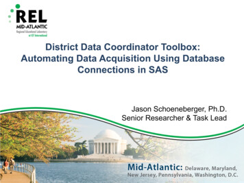
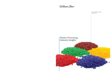
Data Acquisition and Processing ReportLeidos Doc 18-TR-011A. EQUIPMENTA.1 DATA ACQUISITIONCentral to the Leidos survey system was the Integrated Survey System Computer (ISSC). TheISSC consisted of a dual 8 core processor computer with the Windows 7 (Service Pack 1)operating system, which ran the Leidos Integrated Survey System 2000 (ISS-2000) software.This software provided survey planning and real-time survey control in addition to dataacquisition and logging for bathymetry, backscatter, and navigation data. An Applanix Positionand Orientation System for Marine Vessels (POS/MV) and Inertial Measurement Unit (IMU)were used to provide positioning, heave, and vessel motion data during these surveys. Side scansonar (SSS) data were acquired using the Klein Marine Systems, Inc. (Klein) SonarPro softwarerunning on the Leidos Side Scan Acquisition computer (SS-ACQ) which also consisted of a dual8 core processor computer with the Windows 7 (Service Pack 1) operating system. The SS-ACQwas integrated with the ISSC for timing and navigation.A.2 DATA PROCESSINGPost processing was performed on the survey vessel (M/V Atlantic Surveyor) and in the Newport,RI, Data Processing Center (DPC). Multibeam and side scan data were processed and reviewedon computers with the Linux operating system, which ran Leidos’ SABER (Survey Analysis andArea Based EditoR) software. Onboard the M/V Atlantic Surveyor and in the Newport, RI DPC,data were stored on a Network Attached Storage (NAS) system that all computers were able toaccess. See Appendix II for a detailed data processing flow diagram.A.3 SURVEY VESSELFor this project, Leidos employed one survey vessel, the M/V Atlantic Surveyor (Figure A-1).Table A-1 presents the characteristics for the vessel.The M/V Atlantic Surveyor was equipped with an autopilot, echo sounder, Differential GlobalPositioning System (DGPS), radars, and two 40 kilowatt (kW) diesel generators.Accommodations for up to twelve surveyors were available within three cabins.Project: OPR-K371-KR-17102/16/2018
Data Acquisition and Processing ReportLeidos Doc 18-TR-011Figure A-1: The M/V Atlantic SurveyorTable A-1: Survey Vessel Characteristics; M/V Atlantic SurveyorVessel NameM/V xSpeed(knots)Gross .0 Net TonsDeck Load65.0 Long Tons900D582365Leidos outfitted the M/V Atlantic Surveyor with the following major data acquisition systems forthe survey effort:x POS/MV 320 version V5 and IMU type 36x Teledyne RESON (RESON) SeaBat 7125 SV multibeam echo sounder (MBES)x Klein 3000 dual frequency SSSx Moving Vessel Profiler 30 (MVP30) originally manufactured by Brooke Ocean and now apart of AML OceanographicThe side scan winch and four International Organization for Standardization (ISO) containerswere secured on the aft deck. The first 20-foot container was used as the real-time survey dataacquisition office, the second 20-foot container was used for the onboard data processing office,and the third 20-foot container was used for spares storage, maintenance, and repairs. A fourth10-foot ISO container was also mounted on the aft deck which housed an 80 kW generator thatprovided dedicated power to the side scan winch, ISO containers, and all survey equipment. ThePOS/MV IMU was mounted approximately amidships, below the main deck, port of the keel.The RESON SeaBat 7125 SV transducer and RESON SVP 70 surface sound speed sensor werehull-mounted approximately amidships, port of the vessel’s keel. The MVP30 was mounted onthe starboard stern quarter. Configuration parameters, offsets, and installation diagrams for allequipment are included in Section C of this Report.Project: OPR-K371-KR-17202/16/2018
Data Acquisition and Processing ReportLeidos Doc 18-TR-011Further details about the vessel, acquisition systems and software, and processing systems andsoftware are provided in the sections below.A.4 LIDAR SYSTEMS AND OPERATIONSLeidos did not use a lidar system on these surveys.A.5 MULTIBEAM SYSTEMS AND OPERATIONSThe real-time MBES acquisition system used for these surveys included each of the followingunless otherwise specified:x Windows 7 workstation (ISSC) for data acquisition, system control, survey planning,survey operations, and real-time Quality Control (QC).x A RESON SeaBat 7125 SV, with a RESON SVP 70 sound speed sensor (see Appendix IVfor the RESON SVP 70 calibration reports), was used for all MBES data collection. Thesystem was used for the survey season through 18 November 2017, at which time it wasremoved from the ship and the receiver was sent to RESON for factory repair andservicing. On 01 December 2017, the RESON SeaBat 7125 SV with a new receiver wasreinstalled onboard the M/V Atlantic Surveyor and used through the end of surveyoperations in 2017. The RESON SeaBat 7125 SV is a single frequency system operatingat 400 kilohertz (kHz). It has three beam configurations: 256 Equi-Angular, 512 EquiAngular, or 512 Equi-Distant beams. In all configurations the beams are dynamicallyfocused resulting in a 0.5 degree across-track receive beam width and a 1.0 degree alongtrack transmit beam width with a 130 degree swath (65 degrees per side). The RESONSeaBat 7125 SV was set to the 256 beams Equi-Angular mode during survey operations.The maximum ping rate was manually set to 50 hertz (Hz) with the maximum ping ratebeing controlled by the selected range used. During item investigations and holiday datacollection the RESON SeaBat 7125 SV was set to either the 256 beams Equi-Angular or512 beams Equi-Angular mode.RESON SeaBat 7125 SVFirmwareVersion/SN7-P Sonar Processor1812005400 kHz Projector4709011EM7216 Receive Array2210031EM7216 Receive Array47150407k Upload Interface3.12.7.37k Center3.7.11.147k I/O3.4.1.11RESON SVP 70 SSV sensor0213031Project: OPR-K371-KR-17302/16/2018
Data Acquisition and Processing ReportxLeidos Doc 18-TR-011POS/MV-320 Position and Orientation System Version 5 with a Trimble ProBeaconDifferential Receiver (Serial Number [SN] 0220186953) was used as the primarypositioning sensor.POS/MV 320 V5SystemVersion/Model/SNMV-320Ver5SERIAL TING SYSTEM6.4.1IMU TYPE36PRIMARY GPS TYPEBD982OPTIONSRTK-0, THV-0, DPW-0xC-Nav 3050 GPS Receiver (SN 23469) (secondary positioning sensor) with TrimbleSPS356 GPS and DGPS Receiver (SN 5527R35049) (configured as DGPS input source forthe C-NAV).xMVP30 with interchangeable AML Smart Sound Velocity and Pressure (SV&P) Sensorsand a Notebook computer to interface with the ISSC and the deck control unit (See SectionA.7 for additional details concerning sound speed and Appendix IV for the SV&P Software302.214523533254545455SV&P SensorsxOne Seabird Model SBE 19 Conductivity, Temperature, Depth (CTD) profiler was usedduring the Sea Acceptance Tests (SAT) but was not used during any hydrographic datacollection (See Section A.7 for additional details concerning sound speed and Appendix IVfor the CTD Sensor calibrations). Seabird SBE-19 (SN 194275-0648) remained onboardthe M/V Atlantic Surveyor for the duration of the survey season as a backup sensor to theMVP30.SBE CTDSystemSBE-19SoftwareProject: OPR-K371-KR-17Version/SN194275-06481.59402/16/2018
Data Acquisition and Processing ReportxLeidos Doc 18-TR-011One AML Oceanographic BasexX2 sound velocity and pressure sensor was used during theSAT but was not used during any hydrographic data collection (See Section A.7 foradditional details concerning sound speed and Appendix IV for the sensor calibrations).AML BasexX2 SN 025410 remained onboard the M/V Atlantic Surveyor for the duration ofthe survey season as a backup sensor to the MVP30.AML Base XSystemAML BasexX2SVxXchangePxXchangeSeacast h shaft RPM sensors for real-time calculation of dynamic draft.Notebook computer for maintaining daily navigation and operation logs.Uninterrupted power supplies (UPS) for protection of the entire system.Leidos maintains the ability to decrease the usable MBES swath width for the RESON systemsas necessary to maintain data quality and meet the required IHO specifications. During datacollection, swath data were flagged as either Class 1 to 10 degrees (5 degrees per side) or Class 2to 120 degrees (60 degrees per side). Swath data flagged as Class 1 or Class 2 were used for gridgeneration while data outside of Class 2 were flagged as ignore (but were retained for potentialfuture use). Class 1 data were used for grid generation of cross line data used in junctionanalysis (See B.2.2 below for details). The final cumulative grid was generated using Class 2(120 degree) data.The resultant achievable MBES bottom coverage was controlled by the set survey line spacingand the various water depths within the survey areas. The survey line spacing was 80 meters foruse with a SSS range setting of 50 meters. Using 60 degrees as the acceptable swath, 100percent multibeam coverage was not achieved in all areas, nor was it required by the ProjectInstructions. Leidos chose to achieve the Complete Coverage requirement outlined in the ProjectInstructions using Option B) 100% side scan sonar coverage with concurrent multibeambathymetry collection with complete coverage multibeam developments of contacts and features.All MBES data and associated metadata were collected and stored on the real-time surveycomputer (ISSC) using a dual logging architecture. This method ensured a copy of all real-timedata files were logged to separate hard drives during the survey operations. On the M/V AtlanticSurveyor these files were archived to the on-board NAS for initial processing and QC review atthe completion of each survey line.File names were generally changed at the end of each line. This protocol provided the ability toeasily associate each consecutive MBES GSF file, which is denoted by time “ hhmmss.gsf,”with a specific survey line. Occasionally, when surveying holiday fills and/or iteminvestigations, groups of multiple survey lines of the same type were collected to the same GSFfile. If a file was not manually changed between a mainscheme and crossline, the MBES GSFfile was split during post processing. This procedure utilized the SABER command lineprogram gsfsplit. This program provided the ability to split GSF files so that each survey lineProject: OPR-K371-KR-17502/16/2018
Data Acquisition and Processing ReportLeidos Doc 18-TR-011was unique to a single MBES GSF file or set of files. In all cases, mainscheme and crosslinedata were delivered in separate GSF files.When a MBES file needed to be split, a copy of the original GSF file was made and the gsfsplitprogram was then run on the copied file. Using the ping flags stored in the GSF file, gsfsplitsplits the file midway through the offline pings between survey lines. Each newly created fileresulting from the splitting process was given an extension of “a” and “b”. Once the file splitprocess was complete, the newly created files were manually renamed in the following manner:the first survey line kept the name and time of the original split file and each subsequent surveyline was assigned a new name based on the time within the file where the split occurred.GSF file lists were updated to include the split files which were placed in chronological order.All file splits were documented in the “Multibeam Processing Log” provided in Separates I ofeach sheet’s DR.At the end of each survey day all raw real-time data files from the day were backed-up to anexternal hard drive. All processed data on the field processing computers were backed-up to anexternal hard drive intermittently throughout the day and by digital magnetic tape approximatelyevery three to five days. The external hard drives and the digital magnetic tape back-ups wereshipped approximately every 12-14 days to the Leidos DPC in Newport, RI for final processingand archiving.Leidos continuously logged MBES data throughout survey operations collecting all dataacquired during turns and transits between survey lines. Leidos utilized ping flags within theGSF files to differentiate between online/offline data. Online data refers to the bathymetry datawithin a GSF file which were used for generating the Combined Uncertainty and BathymetricEstimator (CUBE) Depth surface. See Section B.2.7 for a detailed description of MBES pingand beam flags. Information regarding the start and end of online data for each survey line isfound in the “Watchstander Logs” and “Side Scan Review Log” that are delivered in Separates Iof each sheet’s DR.Lead line comparisons were conducted to provide Quality Assurance (QA) for the RESONSeaBat 7125 SV. These confidence checks were conducted to comply with Section 5.2.3.1 ofthe HSSD. Lead line comparison confidence checks were performed as outlined in the followingsteps:x The static draft of the survey vessel was measured immediately prior to the beginning ofthe comparison. The value was entered into the ISS-2000 real-time parameters for themultibeam (see Section C.1.1 of this report for a detailed description of how static draft ismeasured).x Correctors to the multibeam data, such as real-time tides and dynamic draft, were disabledin the ISS-2000 system.x A sound speed profile was taken and applied to the multibeam data.x A timekeeping device was synchronized to the time of the ISS-2000 data acquisitionsystem in order to accurately record the time for each lead line depth observation made.x Ten depth measurements were acquired on each side of the vessel at the location of themultibeam transducer.Project: OPR-K371-KR-17602/16/2018
Data Acquisition and Processing ReportxxxLeidos Doc 18-TR-011The current Julian Day (JD), date, vessel draft value, the multibeam data file(s), and thesound speed profile file were entered in the “Lead Line Comparison Log” (Separates I).The observed time and depth of each lead line measurement were entered in the “LeadLine Comparison Log”.The concurrent multibeam depth measurements recorded in the GSF file were then enteredin the “Lead Line Comparison Log”.Lead line depth measurements were made using a mushroom anchor affixed to a line and a tapemeasure (centimeter resolution). The measurements taken provide the distance from the seafloorto the top of a 0.02 meter square metal bar protruding from the port and starboard side’s maindeck. At least ten separate depth measurements and corresponding times were recorded for boththe port and starboard sides. The measurements were recorded into the spreadsheet which usesthe static draft measurement to calculate the water depth.Once all lead line measurements and times were recorded in the lead line spreadsheet, the LeidosExamGSF program was used to view the data within the multibeam GSF file which was loggedconcurrently. The depth value recorded in the multibeam file at the time of each lead linemeasurement and at the appropriate across track distance from nadir was entered into the leadline spreadsheet. The lead line spreadsheet calculated the difference and standard deviationbetween the observed lead line measurements and the acoustic measurements from themultibeam system. Results of the lead line comparison were reviewed and if any differences ordiscrepancies were found, further investigation was conducted. Lead line results are includedwith the survey data in Section I of the Separates of each sheet’s DR and Appendix II of thisReport for the initial and bounding Sea Acceptance Test (SAT) confidence checks.In accordance with the HSSD and the Project Instructions, Leidos collected MBES backscatterwith all GSF data acquired. The MBES settings were checked to ensure acceptable qualitystandards were met and to avoid any acoustic saturation of the backscatter data. The MBESbackscatter data acquired were written to the GSF in real-time by ISS-2000 and are delivered inthe final GSF files for each sheet.A.6 SIDE SCAN SONAR SYSTEMS AND OPERATIONSThese survey operations were conducted at set line spacing optimized to achieve 100% side scansonar coverage.The side scan sonar systems used for these surveys included:x A towed Klein Marine Systems Inc. (Klein) 3000 digital SSS towfish (SN 534 and 535)with a Klein K1 K-wing depressor.x Windows 7 workstation (SS-ACQ) running Klein’s SonarPro software for dataacquisition, side scan system control, logging of SSS data, and real-time QC.x Klein Transceiver Processing Unit (TPU) (SN 418 and 420).x MacArtney sheave with cable payout indicator.x Sea Mac winch with remote controller.x Uninterrupted power supplies (UPS) for protection of the entire system (except thewinch).Project: OPR-K371-KR-17702/16/2018
Data Acquisition and Processing ReportLeidos Doc 18-TR-011The Klein 3000 is a conventional dual frequency SSS system. The 16-Bit digital SSS data werecollected at 100 kHz and 500 kHz concurrently. All SSS data delivered are 16-Bit digital data.The SSS ping rate is automatically set by the TPU based on the range scale
Data Acquisition and Processing Report Leidos Doc 18-TR-011 Project: OPR-K371-KR-17 1 02/16/2018 A. EQUIPMENT A.1 DATA ACQUISITION Central totheLeidos survey