Transcription
ATTACHMENT 9"Data Acquisition System Installation and Test Procedure," TestProcedure, GE Report 26A6499, Revision 2, dated April 22, 2005
26A6499REV. 2GEFNuclEneurjSH NO. 1OF 20EIS IDENT:REVISION STATUS SHEETDATA ACQUISITION SYSTEM INSTALLATION AND TEST PROCEDUREDOCUMENT TITLELEGEND OR DESCRIPTION OF GROUPSTYPE:FMF:I -DENOTESTEST PROCEDUREQUAD CITIES 2CHANGEMPLNO:B13-D001SAFETY-RELATED CLASSIFICATION CODE NTCREVISIONFEB 07 20050RMCN056641RMCN060232JC LAWIIRJARMCN06089ENGR: JC LAWAPR 19 2005APR 22 2005 .PRINTS TOMADEBYAPPROVALS01/25/05JF O'CONNORCHKD BY:02/15/05RS TSUKIDAISSUED02/15/05VA RAMANIMS WORD (2000)GENERAL ELECTRIC COMPANY175 CURTNER AVENUESAN JOSE CALIFORNIA 9512526A6499FEB 15 2005RJ AHMANNCONT ON SHEET 21
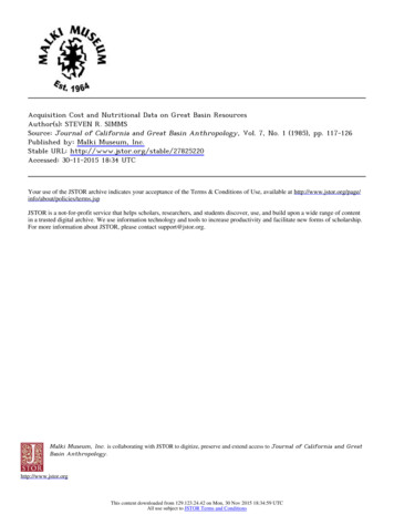
wGENuclearElnetgy26A6499IREV.2SH NO. 2OF20Table of Contents1.02.03.04.05.06.07.08.09.010.0SCOPE .3REFERENCE DOCUMENTS .34.ACCESSORIES AND EQUIPMENT REQUIRED .DATA ACQUISITION SYSTEM INSTALLATION .4.4STRAIN GAGE CHANNELS CHECKOUT PROCEDURE . 6PRESSURE TRANSDUCER CHANNEL FIELD CALIBRATION . 78ACCELEROMETER CHANNEL FIELD CALIBRATION PROCEDURE . 8910STRAIN GAGE CHANNELS FIELD CALIBRATION .LMS DATA ANALYZER SETUP .11TAPE RECORDER CHECKOUT .12List of Figures and TablesFigure 1. Data Acquisition System Layout .13Figure 2. Steam Dryer Strain Gage Wiring .14Figure 3. Main Steam Line Strain Gage (Inside Drywell) Wiring .15Figure 4. Main Steam Line Strain Gage (Outside Drywell) Wiring .16Figure 5. Pressure Transducer Wiring .17Figure 6. Accelerometer Wiring .18Table 1. Strain Gage, Pressure Transducer and Accelerometer Resistance Measurement at QC2 Priorto Ml Cable Termination to Drywell Cables .19Table 2. Strain Gage Resistance Measurement and Calibration After MI Cable Termination toDrywell Cables2. 20
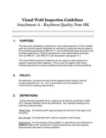
GENudlearEneryW1.026A6499REV. 2SH NO.3OF 20SCOPEAs part of the QC2 Steam Dryer Instrumentation program, a temporary data acquisitionsystem was designed to measure the flow-induced vibration of the newly designed steamdryer and oscillating pressure within the reactor dome and steam lines. The steam dryer willbe instrumented with strain gages, accelerometers and dynamic pressure transducers.Inaddition, the steam lines will be instrumented with strain gages on the outer surface at selectedlocations to obtain the oscillating pressure within the pipe. The purpose of this document is todescribe the procedure for installing and testing the data acquisition system with all thesensors connected prior to plant startup.2.0REFERENCE DOCUMENTSa.Dryer Vibration Instrumentation Design Specification, 26A6395b.Steam Dryer Vibration Instrumentation Installation Specification, 26A6493c.Data Acquisition System Specification, 26A6366d.Functional Test Procedure for Sensors, 26A6484e.Functional Test Procedure for JB and DAS, 26A6484f.Signal Conditioning Enclosure, 105E3903g.Wiring Diagram, 105E33902h.Junction Box, 234C6957i.Charge Converter Enclosure, 234C6958j.Strain Gage Jumper Cable, 234C7123k.Pressure Transducer/Accelerometer Jumper Cable, 234C71351.Instruction Manual for Kyowa Signal Conditioner Model MCD-16A.m.Instruction manuals for Vibro-Meter (VM) Signal Conditioner UVC689, ChargeConverter IPC629 and Galvanic Separator GSI 130.n.Instruction manual for Vibro-Meter Charge Generator Model TSU 109.o.Sensor sensitivity data sheets for pressure transducers, accelerometers and strain gages.p.Users Manual for LMS SCADAS-Ill.q.Users Manual for Sony SIR 1000 Tape Recorder
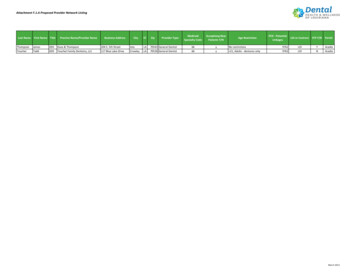
GENucearEneiryW3.026A6499REV.2SH NO. 4OF20 ACCESSORIES AND EQUIPMENT REQUIREDa.Digital Multi-Meter (DMM)b.Vibro-Meter Charge Generator, Model TSU 109c.Oscilloscope, dual channeld.Cabinet with Signal Conditioning Components for Pressure Transducers/Accelerometers(Vibro-MeterUVC 689and ABE-022 with input/outputcables,transducerinterconnecting cable, Galvanic Separation Unit GSI-130) and Sony Tape Recordingequipment (SIR-1000 tape recorder, SCX-32 expansion units and SAA-24 powersupplies) installed.e.Cabinet with strain gage signal conditioning components (Kyowa MCD-16A withmonitor DPE-71A, strain gage amplifier DPM-71A, input/output cables) and LMSequipment (SCADAS 316 front end and SCADAS 317 slave) installed.f.Charge Converter boxes with Charge Converters (VM IP-629) installed.g.Junction Boxes with strain gage Printed Circuit (PC) boards and straight through PCboards installed.h.BNC cables to connect Kyowa and Vibrometer amplifiers output to LMS and TapeRecorder input.4.0i.LMS SCADAS-III Data Acquisition Systemj.Sony SIR 1000 Tape Recorder or equivalentk.120 Ohm Half Bridge Strain Gage simulator.1.350 Ohm Quarter Bridge Strain Gage Simulator.m.12 Volt Power SupplyDATA ACQUISITION SYSTEM INSTALLATION4.1General:The Data Acquisition System (DAS) consists of two cabinets (Section 2.0.f) located inthe data collection area. The first cabinet, Cabinet-1, contains signal conditioningequipment for the dynamic pressure sensors and accelerometers. It also contains a taperecorder for recording output signals from all signal conditioning amplifiers.Thesecond cabinet, Cabinet-2, contains all strain gage signal conditioning amplifiers. In
--26A6499REV.2GENuclearEnergyWSH NO. 5OF20addition, it contains a data analysis unit, which will interface with a desktop computeron a table nearby. The DAS layout is shown in Figure 1. There are two Junction Boxes(JB's) (Section 2.0.h), which will be located a few feet from the DAS cabinets. The firstJB, JB-1, is for termination of cables coming from the dryer sensors and the second JB,JB-2, is for the main steam line sensors (strain gages). Both junction boxes containstrain gage bridge completion resistors and shunt calibration resistors installed onprinted circuit boards. These printed circuit boards also have relays powered by anexternal DC voltage source to activate the shunt calibration resistor across the straingages during shunt calibration. The pressure transducer and accelerometer leads connectto a different type of printed circuit board containing test pins.4.2 Installation Procedure:4.2.1Easy access to the equipment is required for strain gage resistance measurementsbefore and during the test. The location of the enclosures shall follow theseguidelines.4.2.2Install the DAS cabinets, Cabinet-I and Cabinet-2, and the Junction Boxes in thedata collection location. Allow a minimum of 3 feet clearance behind and 6 feetclearance in front of each cabinet for accessibility.4.2.3Install both JB's near the cabinets (-3-6 feet). JB-1, which contains dryer sensorcable terminations, shall be closer to Cabinet-I.JB-2, which contains mainsteam line strain gage cable terminations, shall be located near Cabinet-2, whichcontains the strain gage amplifiers.4.2.4Terminate the cable leads originating from the dryer sensors (pressuretransducers, accelerometers and strain gages) to the left side of the PC boardconnectors in JB-1 (when viewed from front). Similarly, terminate the cableleads from the steam line strain gages to the left side of the PC boards in JB-2.4.2.5Connect the jumper cables for the pressure transducers/accelerometers (Section2.0.k) between the right side of the PC boards in JB-1 and the GalvanicSeparators (GSI-1 30) at the back of Cabinet-1.
GENuclearEnetryW4.2.626A6499 REV. 2SH NO. 6OF 20Connect one end of the strain gage jumper cables (Section 2.0j) to the right sideof the strain gage PC boards in JB-I and JB-2. Connect the other end to theKyowa strain gage amplifier inputs located in Cabinet-2.4.2.7Connect all of the outputs from the amplifiers to both the Sony SIR-1000 'taperecorder input and to the data analyzer (LMS SCADAS-III) using coaxial BNCcables and BNC tee connectors.5.0STRAIN GAGE CHANNELS CHECKOUT PROCEDURE5.1The dryer strain gage channels will be tested one channel at a time. The strain gagewiring diagrams for steam dryer and main steam line gages (inside and outside thedrywell) are shown in Figure 2, Figure 3 and Figure 4, respectively. This test shall beperformed after the wiring is completed from the JB to the LEMO connectors at thedrywell, but before the strain gages are connected. The cable lead resistances shall bemeasured between JB-I and the LEMO connector end in the drywell and recorded. It isalso necessary to check that the cable leads and shields are not crossed between theLEMO connector at the drywell and the JB.5.2 Connect the 120 ohm half bridge simulator (Section 3.0.k) to the LEMO connector atthe drywell. Remove the connector from the PC board in JB-1 and measure and recordthe resistances between three leads. Re-install the connector on to the PC board aftermeasuring the resistance.5.3Proceed with the following steps for setting up the Kyowa strain gage amplifiers:a.Set the switches on all DPM-71A on MCD-16A as follows:* Range switch to OFF* Monitor switch to the Right (not monitoring) except the first channel (to theLeft for monitoring the amplifier output on the DPE-71A monitor)* Filter switch to 1 kHzb.Set the amplifier output monitor DPE-71A switches as follows:* Meter monitor switch to DC* Bal-Cal switch to the Left (unlock).c.Turn the MCD-16A power on. After few minutes connect the MCD-16A output toan oscilloscope and to a DMM (set for Voltage mode).
0GENuclearEnergyd.26A6499REV. 2SH NO. 7OF 20Turn the Range switch of DPM-71A (first channel only) to 50 X 100 pe range andpush the Balance button twice quickly to balance the bridge. The output of theamplifier should be /- 10 mV DC or less. Now change the Range setting througheach range until set to 2 X 100 pe. Balance the bridge by pushing the Balancebutton twice quickly and the output should be less than /-10 mV DC. Furtherbalance can be achieved by adjusting the Zero Potentiometer. The output can beread from the Monitor, Oscilloscope and the DMM. Record the amplifier outputnoise level peak-to-peak from the Oscilloscope time trace.e.Set the DC Power supply to 12 Volts and connect the 12V DC source to the PCboard to activate the relay for applying the shunt calibration resistor across thestrain gage. Record the DC output from the strain gage amplifier.f.Turn off the power to the shunt cal resistor relay. The amplifier output should beclose to zero volts ( /- 10mV DC). This completes the checkout for the firstchannel.g.Turn the Range switch to OFF. Turn the next channel Monitor switch to the Left(Monitoring enabled) and the previous channel Monitor switch to the Right (notmonitoring).h.Repeat steps 5.3a through 5.3g for the rest of the steam dryer strain gage channels.i.To test the main steam line strain gage channels and the junction box, repeat steps5.3a through 5.3g using the 350 Ohm quarter bridge strain gage simulator (Section3.0.1) on each strain gage pair, instead of the 120 ohm half bridge simulator.6.0PRESSURE TRANSDUCER CHANNEL FIELD CALIBRATION6.1The pressure transducer channels will be tested one channel at a time. The signalconditioning components for the pressure transducers and the accelerometers are madeby Vibro-Meter (VM) and are identical except the amplifiers used for the accelerometerchannels have additional features for double-integrating the acceleration signals toobtain displacement. The circuit diagram for the pressure transducer channels is shownin Figure 5. The procedure is as follows:a.Complete the field wiring from JB-1 to the Charge Converter Boxes (Section 2.0.i)in the drywell.Measure cable lead resistances between JB-1 and the Charge
GENucearEnetryW26A6499REV.2SH NO. 8OF20 Converter Box as described in Section 5.1. Connect all the 25 ft Low NoiseJumper cables (VM part number EC-271) to the corresponding charge converterinputs. Also, complete the wiring between JB-1 to Cabinet-I as outlined in 4.2.14.2.3.b.Set the VM UVC 689 Position switch to 1, the gain potentiometer to 1.0(1.0 is the minimum. Do not force the potentiometer to go below the minimum)and the multiplier switch to X 1. Turn on the Power to the VM Rack and connectthe first channel output to the Oscilloscope and to a DMM (set for AC Voltagemode).c.Connect the portable Charge generator to the Vibro-Meter low noise cable LEMOconnector. Set the charge generator dial and multiplier so that it outputs a chargeequivalent to 5 psi peak at50 Hz for that particular pressure transducer, which isavailable from the sensor data sheets. (Example: if the transducer sensitivity is 15pC/psi, then adjust the charge output to 75 pC peak for an equivalent 5 psi peak.)d.Apply the charge by pushing the momentary switch and watch the Oscilloscopeand DMM. Adjust the gain such that the output is 5 Volts peak. Record UVC-689amplifier settings. The channel is now field calibrated for I Volt/psi.e.Follow the procedure for the rest of the channels by repeating 5.1a through 5.1d.Note: all but two of the channels are for VM pressure transducer CP 104. Theremaining two channels are VM pressure transducer CP 211.The transducersensitivity for CP211 is about 1/8 of that of CP104. Hence it will be necessary toinput a different value based on the sensitivity data sheet for these sensors. Thiscompletes pressure transducer channel checkout and calibration.7.0ACCELEROMETER CHANNEL FIELD CALIBRATION PROCEDURE7.1Checking the accelerometer channels is similar to checking the pressure transducerchannels. The wiring diagram for accelerometer channel is shown in Figure 6 and it isvery similar to that of pressure transducer channel. The signal conditioning amplifiersfor accelerometer channels, VM-UVC689, have additional features for doubleintegration. The nominal sensitivity of the accelerometers (VM-CA901) used for thisprogram is 10 mV/G. The accelerometer channels will be calibrated such that 1 V
GENuclearEnergy26A6499REV.2SH NO. 9OF20represents 1 G in acceleration mode (UVC 689 in switch position 1) and the same 1 Voltto represent 10 mils in displacement mode (UVC 689 in switch position 3). Theprocedure is as follows:a.Follow steps 6.1.a and 6.1.b, which describe the procedure for connecting cablesand setting the amplifier gain and switch positions.b.Connect the portable Charge Generator to the Vibro-Meter low noise cable LEMOconnector. Set the charge generator dial potentiometer and multiplier so that itoutputs charge equivalent to 5 G peak at 31 Hz sine wave. (Example: if thetransducer sensitivity is 10 pC/G, then adjust the charge output to 50 pC peak foran equivalent 5 G peak). The charge sensitivity for each particular accelerometeris available from the sensor data sheets.c.With the Position switch set to 1 on UVC 689, apply the charge by pushing themomentary switch.Monitor the amplifier output on the DMM and theOscilloscope. Adjust the amplifier gain such that the output is 5V peak. Thefrequency will remain the same at 31 Hz sine wave. The channel is now calibratedfor 1V/G.d.Change the Position switch on UVC 689 to position 3. The same 5G peak at 31Hzrepresents 50.9 mils peak after double integration (displacement Acceleration/(27co'2e.Apply the charge. The amplifier output should be 5.09 Volt peak (based on IV 10 mils). Record the actual output volts, gain and the amplifier switch settings.f.Repeat steps 7.1.a through 7.1.e for the rest of accelerometer channels.completes the testing of accelerometer channels;Thisl
GENucdearEnertyW8.026A6499REV.2SH NO. 10OF20STRAIN GAGE CHANNELS FIELD CALIBRATION8.1The strain gage channels will be calibrated only after connecting all the strain gages.For pressure transducers and accelerometers, further calibration is not possible afterconnecting the sensors.The following procedure describes the steps involved incalibrating the strain gages.a.With all sensors connected, remove the quick disconnect terminals from the PCboards and measure the resistance readings of each strain gage. Record the values(Table-2) and re-install the connector to the PC board.b.Strain gage resistances, lead wire resistances and natural gage factors will changewith temperature and hence the initial calibration process has to be repeated atelevated temperature (-540 deg F) when the reactor reaches operationalconditions.c.After completion of the resistance measurements, calculate the equivalent strainoutput when a shunt calibration resistor (I Meg-Ohm) is applied across the straingage as shown on Table-2.d.Follow steps 5.3.a to 5.3.d for setting up the Kyowa amplifiers and balancing thebridge.e.Apply I Meg-Ohm calibration resistor by activating the relays on the strain gagePC boards with 12 V DC power and observe the DC output from the amplifier.f.Adjust the Vernier with a small screwdriver to get desired output based on thecalculated equivalent micro strain and engineering units per volt (Table-2). Thedesired sensitivity is 1 V equals 100 micro strain. Higher sensitivity may beobtained by increasing the gain. The filter setting can be changed to a lower valueto eliminate the noise while reading the output DC value but, after calibration,remember to set the switch back to 1 kHz. Repeat the process a few times (Shuntcalibration resistor ON and OFF) until the difference agrees with the calculatedvoltage level.g.Follow the same procedure, steps 8.1.a through 8.1.f, for calibrating the MainSteam Line strain gages. The Main Steam Line sensor cables are terminated in JB2 so the strain gage resistances should be measured at JB-2 terminals.
GENuclearneWh.26A6499REV.2SH NO. 11OF20When the reactor reaches elevated temperature (- 500 Deg. F), there is apossibility that the bridge may not balance because of the unequal resistancebetween active and dummy resistor. If the amplifier cannot balance the difference,it will be necessary to install balance resistors on the PC boards.9.0LMS DATA ANALYZER SETUPThe LMS data analyzer front end is located in Cabinet-2 where the strain gage amplifiers arelocated. Connect the BNC input cables from all of the amplifier outputs to the tape recorderinput and also to the LMS system. The LMS chassis interconnects with a Desk Top PCloaded with analysis software to perform frequency and time history analysis.operational instructions are contained in the instruction manual.TheIt will be necessary toundergo training to operate this system and no written instructions are available at this time.Types of analysis used during the testing are Power Spectrum measurements (to determinefrequency composition of the signals and their magnitude), Time History and Histogramanalysis (to get positive and negative peaks of the signals between certain frequency band tobe able to compare with the acceptance criteria) and Transfer Function (to determine phaserelationships between the signals, coherence, correlation). Other detailed analysis will beperformed later at San Jose site while preparing the final report. Typical parameters forPower Spectrum analysis are as follows:*Frequency Bandwidth: 400 Hz**Number of Lines: 800 lines resolution (minimum)*Window: Flat Top Window*Type of Averaging: Peak Hold and Stable Averaging*Number of Averages: 16, 32, 64 (Typical)*Overlap processing: 10 to 90 percent (typically 50 to 80 percent).
-a10.0-GENuclearEnergy26A6499- REV. 2SH NO. 12OF 20TAPE RECORDER CHECKOUTThe Tape Recorder, Sony Model SIR 1000 multi-channel PCM recorder will record all analogsignals to data cartridge. It has variable input range from 0.5 V to 20 V peak and can recordup to 96 channels of data. It can continuously record for 8 hours of data on a single datacartridge and can accommodate a frequency bandwidth from DC to 1.25 kHz.Furtheroperational
i. LMS SCADAS-III Data Acquisition System j. Sony SIR 1000 Tape Recorder or equivalent k. 120 Ohm Half Bridge Strain Gage simulator. 1. 350 Ohm Quarter Bridge Strain Gage Simulator. m. 12 Volt Power Supply DATA ACQUISITION SYSTEM INSTALLATION 4.1 General: The Data Acquisition System