Transcription
Elekta NeuromagData AcquisitionUser’s ManualRelease 4.0February 2007
Elekta NeuromagDATA ACQUISITIONCopyright 2007 Elekta Neuromag Oy, Helsinki, Finland.Elekta Neuromag Oy assumes no liability for use of this document if anyunauthorized changes to the content or format have been made.Every care has been taken to ensure the accuracy of the information in thisdocument. However, Elekta Neuromag Oy assumes no responsibility or liability for errors, inaccuracies, or omissions that may appear in this document.Elekta Neuromag Oy reserves the right to change the product without furthernotice to improve reliability, function or design. This document containscopyrighted and possibly confidential information and is intended for theexclusive use of customers having Elekta Neuromag products and authorizedrepresentatives of Elekta. Disclosure to others or other use is strictly prohibited without the express written authorization of Elekta.This document is provided without warranty of any kind, either implied orexpressed, including, but not limited to, the implied warranties of merchantability and fitness for a particular purpose.Elekta Neuromag , Vectorview, MaxFilter and MaxShield are trademarks ofElekta. Isotrak is a trademark of Polhemus Navigational Sciences, UNIX is atrademark of UNIX System Laboratories, Inc., X Window system is a trademark of X Consortium, Inc., Hewlett Packard, HP-UX and HP-RT are trademarks of Hewlett Packard Company.This product is protected by the following issued or pending patents:WO2005078467 (MaxShield)US2006031038 (Signal Space Separation)US6876196 (Head position determination)FI20050445 (MaxST)Printing HistoryNeuromag p/nSoftwareDate1st editionNM23065A4.02007-02-05NM23065A
Elekta NeuromagDATA ACQUISITIONCONTENTS1 INTRODUCTION . . . . . . . . . . . . . . . . . . . . . . . . . . . . . . . . . . . . . . . . 11.1 Overview . . . . . . . . . . . . . . . . . . . . . . . . . . . . . . . . . . . . . 11.2 Typographical conventions . . . . . . . . . . . . . . . . . . . . . . . 11.3 Software safety. . . . . . . . . . . . . . . . . . . . . . . . . . . . . . . . . 22 GETTING STARTED . . . . . . . . . . . . . . . . . . . . . . . . . . . . . . . . . . . . . 32.1 Hardware checklist. . . . . . . . . . . . . . . . . . . . . . . . . . . . . . 32.2 Starting the software . . . . . . . . . . . . . . . . . . . . . . . . . . . . 32.3 Components of the control program . . . . . . . . . . . . . . . . 42.3.1 The menus52.4 Closing the software. . . . . . . . . . . . . . . . . . . . . . . . . . . . . 63 SETTING UP . . . . . . . . . . . . . . . . . . . . . . . . . . . . . . . . . . . . . . . . . . . 73.1 Project . . . . . . . . . . . . . . . . . . . . . . . . . . . . . . . . . . . . . . . 73.2 Subject . . . . . . . . . . . . . . . . . . . . . . . . . . . . . . . . . . . . . . . 83.2.1 Subject list83.2.2 Volunteers and patients93.3 Acquisition . . . . . . . . . . . . . . . . . . . . . . . . . . . . . . . . . . . 113.4 Stimuli and triggers . . . . . . . . . . . . . . . . . . . . . . . . . . . . 143.4.1 Trigger interfaces and triggering modes143.4.2 Stimulus sequence153.4.3 Sequence generator163.4.4 Loading and saving sequences173.5 On-line averaging. . . . . . . . . . . . . . . . . . . . . . . . . . . . . . 183.5.1 Basics183.5.2 Online averaging dialog193.5.3 Events193.5.4 Categories213.5.5 Artefact rejection233.5.6 Noisy and silent channels243.5.7 On-line display updates243.6 Head digitization . . . . . . . . . . . . . . . . . . . . . . . . . . . . . . 253.6.1 Coordinate frames253.6.2 Digitization263.6.3 Using five coils293.7 Gantry position. . . . . . . . . . . . . . . . . . . . . . . . . . . . . . . . 293.8 Saving and restoring settings . . . . . . . . . . . . . . . . . . . . . 303.9 Setting filters and gains of electric channels . . . . . . . . . 303.10 On-line signal space projection . . . . . . . . . . . . . . . . . . 333.10.1 Background333.10.2 Setting up for on-line SSP333.10.3 SSP and the on-line averager34NM23065Ai
Elekta NeuromagDATA ACQUISITION4 EXPERIMENT PREPARATION. . . . . . . . . . . . . . . . . . . . . . . . . . . . 354.1 Restricted megacq . . . . . . . . . . . . . . . . . . . . . . . . . . . . . 354.2 Saving a preparation. . . . . . . . . . . . . . . . . . . . . . . . . . . . 354.3 Loading a saved preparation . . . . . . . . . . . . . . . . . . . . . 365 ACQUISITION . . . . . . . . . . . . . . . . . . . . . . . . . . . . . . . . . . . . . . . . . 375.1 Acquisition controls . . . . . . . . . . . . . . . . . . . . . . . . . . . . 375.2 Head position indicator . . . . . . . . . . . . . . . . . . . . . . . . . 395.2.1 Normal HPI acquisition395.2.2 HPI fitting395.2.3 Continuous HPI405.3 Raw data display . . . . . . . . . . . . . . . . . . . . . . . . . . . . . . 415.3.1 Controls425.3.2 Channel selections435.3.3 Scales445.3.4 XY display455.4 On-line averaging. . . . . . . . . . . . . . . . . . . . . . . . . . . . . . 465.4.1 Messages465.4.2 Adjusting on-line averaging465.4.3 Marking channels as “bad”465.4.4 On-line average display465.4.5 Select displayed categories475.5 Raw data recording . . . . . . . . . . . . . . . . . . . . . . . . . . . . 475.6 EEG impedance measurements . . . . . . . . . . . . . . . . . . . 485.7 Stopping the acquisition. . . . . . . . . . . . . . . . . . . . . . . . . 496 SAVING DATA . . . . . . . . . . . . . . . . . . . . . . . . . . . . . . . . . . . . . . . . 506.1 Data volumes . . . . . . . . . . . . . . . . . . . . . . . . . . . . . . . . . 506.2 Saving averages and raw data . . . . . . . . . . . . . . . . . . . . 506.3 The saving dialog . . . . . . . . . . . . . . . . . . . . . . . . . . . . . . 516.4 Rescuing data after a crash. . . . . . . . . . . . . . . . . . . . . . . 517 MANAGING DATA VOLUMES . . . . . . . . . . . . . . . . . . . . . . . . . . . . 527.1 Concepts. . . . . . . . . . . . . . . . . . . . . . . . . . . . . . . . . . . . . 527.2 Accessing data . . . . . . . . . . . . . . . . . . . . . . . . . . . . . . . . 527.2.1 Basics527.2.2 Displaying a volume547.2.3 Mounting and unmounting547.2.4 Copying data547.2.5 Initializing MOD's557.3 Listing the contents of a volume . . . . . . . . . . . . . . . . . . 557.4 Backing up a volume . . . . . . . . . . . . . . . . . . . . . . . . . . . 567.5 Restoring data . . . . . . . . . . . . . . . . . . . . . . . . . . . . . . . . 568 RESTARTING THE SOFTWARE . . . . . . . . . . . . . . . . . . . . . . . . . . 57NM23065Aii
Elekta NeuromagDATA ACQUISITION1. INTRODUCTION1.1. OverviewElekta Neuromag Data Acquisition Software is used to control themeasurement device and to acquire data. This manual covers performing measurements with a system that has been installed, configured and tuned. Software installation and basic configurationare explained in “Elekta Neuromag Data Acquisition SoftwareRelease 4.0 Installation Guide”. Tuning is described in “SensorTuner User’s Guide”.For a description of the measurement device, main safety instructions, and a general description how measurements are performed, see “Elekta Neuromag System Hardware User’sManual”.This manual applies only to Elekta Neuromag Data AcquisitionSoftware Release 4.0. The software allows both evoked responsemeasurements and recording of continuous raw data. It also supports MaxShield noise reduction system and provides rudimentary continuous head position tracking capabilities.For a brief description of the software structure, see Appendix A.For changes from previous release, see Appendix B.1.2. Typographical conventionsThe following typographical conventions are used in this manual.commandsTyped commands and text as well as messages on non-graphical screens or windows are shown in typewriter font. Forexample, commands given to the UNIX shell are written inthis font:show fiff -v online.fifThese commands should be typed exactly as shown, including spaces, underscores, hyphens, slashes, punctuation etc.only omitting the constructions denoting parameters (seebelow). When using the graphical user interface, it is necessary to open a terminal window first in order to type the commands.buttons and messagesThe textual items of the graphical user interface are denotedwith bold Helvetica. The names of buttons, menus and menuitems and messages appearing on graphical windows areshown in this font. For example:Select Save averages. from File menu.NM23065AIntroduction1
Elekta NeuromagDATA ACQUISITIONmeans using the mouse or arrow keys to point and activate themenu labeled as “File”, and then moving the pointer to anitem in this menu reading “Save averages.” and selecting it.names and parametersText in italics indicates the name of an application program,manual, or other Neuromag item. Italics is also used to introduce new concepts and to emphasize words.Parameters are marked with italicized text enclosed in anglebrackets ( , ). The whole construction, including the anglebrackets, should be replaced by the value of the parameter.For example, in the shell command described asshow fiff [-v] data file the string data file is substituted with a real file name.Optional parameters or arguments are enclosed in squarebrackets.1.3. Software safetyThis product has been designed for the following intended use:The Elekta Neuromag systems are magnetoencephalographic(MEG) devices which non-invasively detect and display biomagnetic signals produced by electrically active nerve tissue in thebrain. When interpreted by a trained clinician, the data provideuseful information about the location of the nerve tissue responsible for critical brain functions and thus enhances diagnostic capabilities.Warning: MEG data can be inherently explained by many dif-!ferent source distributions, and measurements often contain various kinds of artefacts. Data used for clinical purposes must beinterpreted by a trained clinician who is capable of judging therelevance and quality of the data.Warning: Do not use the system without also carefully reading!NM23065A“Elekta Neuromag System Hardware User’s Manual”.Introduction2
Elekta NeuromagDATA ACQUISITION2. GETTING STARTED2.1. Hardware checklistBefore starting a measurement:1. Check that you have a set of at least three HPI coils available.2. Check that the evoked-response stimulation hardware isproperly set up, if needed.3. Check that the necessary electrodes, paste, and other relateditems are available for recording electric signals.2.2. Starting the softwareAll the Neuromag analysis and data acquisition application programs are started by double clicking the corresponding icon in theNeuromag toolbox. If this toolbox is not on your desktop, openit by first clicking the tools subpanel on the right side of CDEfront panel (see HP Common Desktop Environment: User’sGuide for details) and then double-clicking the Neuromag icon.Once the Neuromag toolbox is open the data acquisition controlprogram (megacq) is started by double clicking the Acquisitionicon. In addition to the main window (see page 4), the raw datadisplay appears (see Section 5.3. on page 41).On start-up, megacq checks the integrity of the data path from thedata acquisition system to the UNIX workstation. If no connection exists, an error dialog indicating the failure pops up. Shouldthis happen, check first that the data acquisition computer isswitched on (see Technical manual: System hardware). A possible software problem causing the error can be resolved by the procedure described in Section 8. on page 57.Here we assume that the system is tuned and that SSP vectorsused in suppression of external artefacts have been set. For detailssee Sensor Tuner User’s Guide and Section 3.10. “On-line signalspace projection” on page 33.Before proceeding it is advisable to check the available disk spaceon data volumes from Disk space in the Tools menu.NM23065AGetting Started3
Elekta NeuromagDATA ACQUISITION2.3. Components of the control programThe main window of megacq consists of:1. The menubar with File, On-line, Tools, and Help menus.2. A log window for informational messages.3. The setup buttons with a synopsis of the setup state indicatednext to each button.4. Acquisition control buttons, which are enabled and disabledaccording to the state of the acquisition process.5. A stopwatch for measuring time.6. Five status message lines indicating the state of the acquisition.NM23065AGetting Started4
Elekta NeuromagDATA ACQUISITION2.3.1. The menusThe items in the File menu store and recall measurement parameters from files, thus facilitating setting up for a measurement. SeeSection 3.8. “Saving and restoring settings” on page 30 and Section 4. “Experiment preparation” on page 35 for the details of theitems in this menu. Finally, there is Quit for exiting the acquisition system.The On-line menu contains functions which control the on-lineaverager and the on-line average display during a measurement.See Section 5.4. “On-line averaging” on page 46 for a descriptionof this menu.Most of the functions in the Tools menu control the magnetometer probe:Reset channelsReset the MEG and EEG channels. To ensure fast settling ofthe signals after resetting the electronics the digital high-passfilter is automatically switched to a high corner frequency fora couple of seconds and then back to the setup value.A reset is applied automatically when a measurements starts,so this function is intended for recovering channels after anexcessive disturbance during a measurement.Tuner.Invoke the automatic sensor tuner. For details see SensorTuner User’s Guide.Squiddler.Invoke the manual sensor tuner, which allows modifying,loading and saving tuning parameters, and de-trapping (heating) the sensors. Refer to Technical Manual: System Hardware for instructions how to tune the sensors. Squiddler canalso be started independently of megacq by using the corresponding icon in the Maintenance folder in the Neuromagtoolbox.Squiddler EEG.Invoke the EEG hardware (Vectorview) or EEG filter (Neuromag-122) control program. The applicability of thisdepends on the configuration of the particular system.Helium level.Show the liquid Helium level history and estimated zerolevel time. This can be done also by clicking the HeliumLevel icon in the Neuromag toolbox or by issuing the command helium at a command line (provided that the searchpath of the UNIX shell includes the directory /neuro/bin).Disk space.Show the available disk space on all mounted volumes.NM23065AGetting Started5
Elekta NeuromagDATA ACQUISITION2.4. Closing the softwareWhen the measurements are completed and all the necessary datasaved, the acquisition system user interface can be closed torelease computer resources for other tasks. To close the acquisition programs select Quit in the File menu of megacq. You willbe asked for a confirmation.All the child applications of megacq (Raw data display, Averageresponse display etc.) will close automatically.The state of megacq is not automatically saved when closing it.Thus, you have to explicitly use the procedures explained in Section 3.8. “Saving and restoring settings” on page 30 if you want tocontinue using the same parameters.Note that exiting megacq only closes the user interface of the dataacquisition system, while the real-time system remains poweredon and running. The real-time system is shut down only duringservice operations. It is preferable to keep the electronics onbetween measurement sessions; the system requires considerabletime to completely stabilize after a power-up.NM23065AGetting Started6
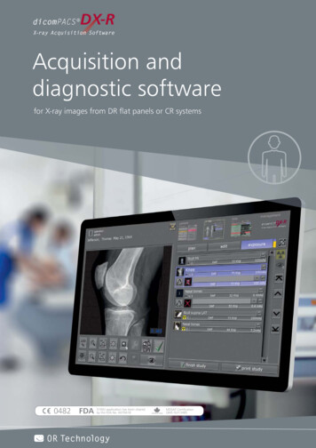
Elekta NeuromagDATA ACQUISITION3. SETTING UPThis section describes the setup tasks to be performed beforestarting the acquisition. If the personal data of the subject areavailable, the setup can be completed before the subject arrives.See “Experiment preparation” on page 35 for more information.3.1. ProjectThe measured data are grouped into projects according to the conventions at each site. For example, one project might correspondto a group of patients with common symptoms or patients investigated by one clinician.The project is selected from the project dialog which appears.when the project setup button is pressedIf you are collecting data to an already existing project, just selectthe project name from the list and press OK or double click theproject name.If you are defining a new project, select the item new from thelist and enter the project name and other reference information inthe text entry areas. The project name may consist of lowercaseletters and the underscore character. In addition to the projectname, aims, and names of responsible persons are required for thedefinition of a new project.NM23065ASetting up7
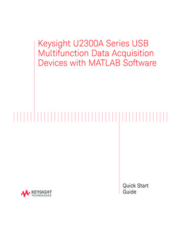
Elekta NeuromagDATA ACQUISITIONIf you are changing to No project double click the item new .If you want to close the project dialog without changing anythingpress Cancel.There are two useful keyboard shortcuts in the project list. First,you can go to the new item by pressing the home key with control down. Second, you can browse the list alphabetically byclicking any of the items and then pressing a letter key. The listwill move to the first project name beginning with this letter.3.2. Subject3.2.1. Subject listSubject definition is analogous to the project definition. Thenames of already existing subjects are listed alphabetically at thetop of the dialog.If you are collecting data from an already existing subject, justselect the subject name from the list and press OK or double clickthe subject name.NM23065ASetting up8
Elekta NeuromagDATA ACQUISITIONTo define a new subject, select the item new from the list, enterthe information to the text fields, select the appropriate choices,and press OK. You are required to enter the first and the last name.Do not to define the same subject twice as a double-entry mayconfuse the MEG/MRI subject matching in the analysis programs.Weight and height are optional whereas handedness and sex arealways taken from the corresponding option menus. HospitalInformation System (HIS) ID is intended for a hospital-widepatient code, such as social security number, which uniquelyidentifies the subject. HIS ID is stored with each data file and itcan be used as a path name component for the saved files.If you are changing to No subject double click the item new .If you want to close the subject dialog without changing anythingpress Cancel.The keyboard shortcuts in the subject list are identical to those inthe project list.3.2.2. Volunteers and patientsSites studying patients would often like to protect patient information from unauthorized access. megacq provides a grouping ofpersons to be studied to ‘volunteers’ and ‘patients’.Volunteers are healthy subjects participating in the MEG studies.When a person is classified as volunteer, megacq applies no special protection on his data:1. The personal data of a volunteer can be read by any user inmegacq. All personal information is included with the measured data.2. The data will be saved - by default - in directories volume / project / last name first name / date ,as discussed in Section 6.1. on page 50. All directories on thepath are accessible to any user.For a person classified as a patient, the following protective measures are taken:1. Only the patient id number will be written to the data files.The data files will contain case as the patient’s first nameand the id number as the last name. Therefore, if you list theperson’s name from a data file it will be something likecase 567.2. The data will be saved - by default - in directories project /case id / date .3. The creator of the patient chooses the access restrictionswhich apply to the personal data of the patient entered and tothe MEG and EEG data saved.NM23065ASetting up9
Elekta NeuromagDATA ACQUISITIONIn the strict access mode, the data are only readable by thecreator of the patient.In the group access mode, read, and write access to the patientdata is additionally granted to a designated group of UNIXusers.The choice between volunteers and patients is made in the optionmenu at the top of the subject definition dialog. When the menuis set to Volunteers, all volunteers are listed.When the menu is set to Patients all patients accessible to the current user are listed.If you have created the patient, the Accessible to group: optionmenu becomes undimmed.If the choice is None the data of this patient are only accessible toyou (the user currently logged in). If you select a group of users,the data become accessible to this group as well. Please consultyour system administrator if you need a new group of users. Thenumber of groups should be kept as small as possible.Note: If you have restarted the acquisition software as describedin Section 8, you can reuse earlier HPI data when megacq is restarted. However, you can change the subject only once (from Nosubject to some available subject) without losing the HPI data.NM23065ASetting up10
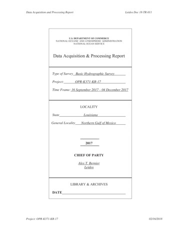
Elekta NeuromagDATA ACQUISITION3.3. AcquisitionThe acquisition setup dialog, which appears when the acquisitionsetup button is pressed, adjusts the following:1.3.2.4.5.6.1. The selection of channels to be acquired.The channels are switched on and off from the correspondingbuttons in the upper part of the dialog.Note: All MEG channels are selected by default. Switching anyof them off should be done with caution. It is better to ignore malfunctioning channels in the analysis software instead of not recording them at all. This enables, e.g., checking if artefacts onother channels are due to malfunctioning channel. In addition,some third party analysis tools assume all channels to be presentin data file.NM23065ASetting up11
Elekta NeuromagDATA ACQUISITIONThe number of electric input channels is system specific. It istypically 64.Each of the electric channels can serve either as an EEG,ECG, EMG, EOG, or a miscellaneous input. The type of eachelectric channel can be changed from a popup menu attachedto each of the electric channel buttons. By default, holdingdown the right mouse button while pointing to an electricchannel button brings up this menu.Typically, EEG hardware channels 1 - 60 are unipolar and 61- 64 are bipolar. Only the latter ones should be used as ECG,EMG, or EOG channels. See “Elekta Neuromag SystemHardware User’s Manual” for description of the EEG hardware.The change of the input type only affects the channel name.This is often useful in the artefact rejection and later stages ofdata analysis. For example, xplotter, the plotting program,may be set up to lay out the EOG channels in an invariableway. Also, the scales of various electric channel types can beseparately set in xplotter and in the raw data display.Channels labeled with STI are stimulus channels whose usageis described in more detail in Section 3.4. on page 14. Channels labeled with MISC are auxiliary electrical input channels.2. The sampling frequency.The sampling frequency, fs, is set with a slider below thechannel selectors.The maximum allowed sampling rate depends on the dataacquisition hardware and on the selection of channels andtheir actual distribution between the analog-to-digital converters in the data acquisition unit. The maximum on the sampling frequency slider automatically reflects the limitationimposed by the hardware.The actual sampling rate may slightly differ from the selectedone because of limitations in the hardware. However, the realsampling rate is reported in the data files and in the information window on top of the main acquisition window.3. Low-pass filterThe low-pass filter corner frequency, fa, is set with a slider tothe right of the sampling frequency slider. The actual filtercorner may differ somewhat from this setting. The real cornerfrequency is saved into data files and reported in the information window. For more detailed low-pass filter specificationsconsult the “Elekta Neuromag System Hardware TechnicalManual”.NM23065ASetting up12
Elekta NeuromagDATA ACQUISITIONAccording to the Nyqvist criterion, the sampling frequencyshould be at least twice the highest frequency component inthe analog signal, fs 2fa to avoid aliasing. Since analog filters cannot have an infinitely steep transition at the corner frequency, megacq adds a safety margin and only allows fs 3fa.4. High-pass filterThe corner frequency of the high-pass filter can be set insteps. The available corner frequencies are shown next to thetoggle buttons provided for selecting the filter.5. Raw data baselineWith this option, it is possible to define the amount of data tobe saved preceding the time when raw data saving wasswitched on. The length of this ‘baseline’ will be at least theindicated amount. The maximum length is 15 seconds. Thisfeature allows keeping the raw data saving off until something interesting happens. When saving is activated, the eventnoticed can be saved, even though it has already gone.6. Use MaxShield feedbackThis option is present only in systems using MaxShield .The toggle button is used to activate or deactivate the internalfeedback system. See “MaxShield User’s Manual”.Note: Filters and gains of EEG amplifiers are controlled througha separate control dialog, described in “Setting filters and gains ofelectric channels” on page 30.NM23065ASetting up13
Elekta NeuromagDATA ACQUISITION3.4. Stimuli and triggersThe electrical stimulus triggers, that mark events for the acquisition software, can be provided either by the data acquisition unitor by an external stimulation system. The acquisition softwareprocesses the trigger signals exactly in the same way, independentof their origin. This section describes the trigger system and generation of triggers.3.4.1. Trigger interfaces and triggering modesThe electric interface of the trigger signals is called a StimulusTrigger Interface Unit, which is connected to the System ControlCard (SCC) housed in the data acquisition system cabinet. ElektaNeuromag systems include two such interface units, which bydefault operate in parallel, i.e. input #1 and output #1 on bothinterface units correspond to trigger line #1 on the combinationtrigger channel (STI101) associated with the 1st interface unit.However, the two interfaces can also be treated separately byturning on (selecting for acquisition) the trigger channel (STI102)associated with the 2nd interface unit. This is done using theacquisition setup dialog.For details about the Stimulus Trigger Interface Unit and for electrical specifications of the trigger pulses, see “Elekta NeuromagSystem Hardware User’s Manual” and “Elekta Neuromag SystemHardware Technical Manual”.The SCC manages both internal and external triggers. Irrespectiveof the triggering mode (internal/external) the trigger pulsesalways appear at the corresponding trigger outputs of both interface units. The principle is shown in the following figure.NM23065ASetting up14
Elekta NeuromagDATA ACQUISITIONInternally generated trigger pulses and the pulses acquired fromexternal sources are logically OR’ed line by line. The pulse is fedto the acquisition system and to the trigger outputs. Thus the system automatically ‘chooses’ the right source for each triggerchannel provided that a trigger channel is not receiving pulsesboth from internal and external sources at the same time. Shouldthis happen, pulses from those two or three sources will be intermixed and indistinguishable at further processing stages.Typically the trigger event is associated with the rising edge oftrigger pulse, however, the off-line analysis tools can be configured to also monitor the falling edge. Note that the timing of thefalling edge does not accurately reflect any physical event in systems which incorporate circuitry that fixes the pulse length.The stimulus setup dialog shown below selects the trigger sourcefrom the software point of view: if internal triggering is selected,you are allowed to define a stimulus sequence.If you prefer external triggering, turn the switch to the externalposition and connect a TTL level trigger pulse output from yourstimulation system to the trigger input.Note: Both internal and external triggers can be used in the samesession.3.4.2. Stimulus sequenceThe stimulus setup dialog appears when you press the stimulussetup button.NM23065ASetting up15
Elekta NeuromagDATA ACQUISITIONEach item in the internal stimulus sequence is defined by the trigger number (1 – 16), the length of the trigger pulse (ms), and thelength of the interval from the start of the trigger to the next. Thisperiod is often called the inter-stimulus interval (ISI).The maximum length of the sequence is 500 stimuli. The minimum pulse length is 5 ms and the minimum ISI is 50 ms. Theremust be at least 50 ms from the end of the trigger to the next.The stimulus sequence can be either entered manually, generatedwith help of the sequence generator, or loaded from a file.3.4.3. Sequence generatorThe sequence generator utility is accessed trough the Generatebutton in the stimulus definition dialog.You can create several kinds of sequences:1. An alternating sequenceGiven number of stimuli, n, are repeated sequentially:1,2, ,n,1,2, ,n, If the ISI limits are equal, the ISI remainsconstant; if they are different, the ISI’s are random within theinterval with a uniform probability density.2. Random sequenceThe given number of stimuli have an equal probability tooccur in the random sequence. The handling of ISI’s is thesame as in the alternating sequence.3. Mismatch sequenceRare (deviant) stimuli occur randomly with given probabilityin a monotonous sequence of standard stimuli. If the deviantprobability is less than 15 percent, two deviant stimuli willnever occur sequentially. Normally stimulus 1 is the standardand stimulus 2 the deviant. If the deviant probability is set tohigher than 85 percent, the roles of the stimuli are reversed.NM23065ASetting up16
Elekta NeuromagDATA ACQUISITIONOnce you click Generate, the sequence is generated and the values are entered into the stimulus sequence table.3.4.4. Loading
Once the Neuromag toolbox is open the data acquisition control program (megacq) is started by double clicking the Acquisition icon. In addition to the main window (see page 4), the raw data display appears (see Section 5.3. on page 41). On start-up, megacq checks the integrity of the data path from the