Transcription
Precision Strain Gagesand SensorsDatabookGeneral PurposeSpecial PurposeWeldableTemperature SensorsResidual Stressmicro-measurements.com
General Information . 6Designation System. 8Selection Chart . 9Selection Criteria . 11Strain Gage Dimensions . 13PrecisionStrain GagesFor technical questions, 5
General InformationStress Analysis Strain GagesHOW TO USE THE LISTINGSGeneral-use Micro-Measurements strain gages are listed in groups according to grid geometry: Linear patterns Delta rosettes Tee rosettes Shear/torque patterns Rectangular rosettesFor each of these grid geometries, those patterns most commonly used by our customers are listed first with completespecifications. Additional listings with partial specifications follow for the less commonly used patterns. In both listings,the gage patterns appear in alpha-numeric order, increasing from the shortest grid lengths to the longest.Some seldom, if ever, ordered patterns listed in previous versions of this databook have been omitted. We will, of course,continue to make these patterns available upon request for customers presently using them. For details, contact theApplications Engineering Department at the Micro-Measurements sales office nearest you.Separate listings are provided for special-use strain gages and sensors: Residual stress Embedment gages Magnetic fields Temperature sensors Weldable gages Crack detection sensors High temperature gages Crack propagation sensors Manganin pressure gages Displacement sensors Shear modulus gagesADVANCED SENSORS GAGESCustomers whose application requires gages for the manufacture ofprecision commercial transducers are strongly encouraged to contact ourApplications Engineering Department. They can provide assistance in theselection of the proper Advanced Sensor for your particular application.CUSTOM GAGESMicro-Measurements maintains the most extensive variety of catalogstrain gages available today. Whether for stress analysis, transducermanufacturing, or special-purpose applications, we have not only a wideselection, but also a large and varied inventory that is readily available forimmediate delivery.However, many of our customers have applications requiring gages thatare manufactured to their individual specifications. While we believe ourwide variety of standard catalog gages will satisfy most requirements, werecognize the need for custom products and are committed to serving it well.To request a quotation for a custom gage, please contact our ApplicationsEngineering Department.www.micro-measurements.com6For technical questions, contactmm@vpgsensors.comDocument No.: 11501Revision: 26-Aug-2015
General InformationStress Analysis Strain GagesAPPLICATIONS SUPPORTMicro-Measurements maintains an experienced and highly trainedapplications engineering staff. Our Applications Engineers are as close asyour telephone, and we urge you to call them for recommendations in straingage selection to satisfy your particular test requirements.TECHNICAL INFORMATIONDetailed technical information about the selection and application ofstrain gages can be found in the special series of Tech Notes, Tech Tips,and Instruction Bulletins on strain gage technology. Thorough familiaritywith these publications will help ensure consistent success in the use ofMicro-Measurements strain gages.We also offer our customers an extensive assortment of additional productand technical literature, available in the strain gage technology knowledgebase on our website N GAGE ACCESSORIES AND INSTRUMENTATIONIn addition to an extensive selection of strain gages, Micro-Measurementsoffers a complete range of complementary products. Strain gageaccessories include surface preparation materials, adhesives, installationtools, protective coatings, leadwire, and a host of other application tools,hardware, and supplies. Instruments range from portable, digital strainindicators, to sophisticated computer-controlled systems for the acquisition,storage, and reduction of test data. Both static and dynamic measuringinstruments are available—each uniquely designed to provide stable,accurate, and reliable strain measurement.TRAINING PROGRAMSTraining customers in the proper use of strain measurement techniques isan essential part of the Micro-Measurements philosophy. In support of thisprinciple, Micro-Measurements conducts an extensive series of regularlyscheduled technical seminars, workshops, and short courses. Courseinstructors are recognized authorities in their field. Training sessions areconducted at our facilities in the United States and Europe, as well as athotels and educational institutions around the world. For schedules, go ning-programs/Document No.: 11501Revision: 26-Aug-2015For technical questions, 7
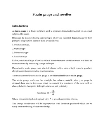
Designation SystemStress Analysis Strain GagesThe Strain Gage Designation System described below applies to Micro-Measurements General-Use Strain Gages.Self-Temperature-Compensation (S-T-C)Active Gage Length in Mils[0.001 in (0.0254 mm)]Foil AlloyGrid and Tab GeometryCarrier Matrix (Backing)Resistance in OhmsOptional FeatureExample:E:Open-faced cast polyimidebacking.CE: Thin, flexible gages witha cast polyimide backingand encapsulation featuringlarge, rugged, coppercoated solder tabs. Thisconstruction providesoptimum capability fordirect leadwire attachment.L2: Thin, laminated, polyimidefilm backing featuringencapsulated grids withpreattached leadwireribbons.C2: Thin, laminated, polyimidefilm backing featuringencapsulated grids withleadwire cables.XXX - XX - XXXXX - XXXA: Constantan alloy inself-temperaturecompensated form.P: AnnealedConstantan.D: Isoelastic alloy.K: Nickel-chromiumalloy (similar toKarma).The S-T-C numberis the approximatethermal expansioncoefficient in ppm/ F ofthe structural materialon which the gage is tobe used. The followingS-T-C numbers areavailable:A: 00, 03, 05, 06, 09,13, 15, 18, 30, 50P: 08, 40K: 00, 03, 05, 06, 09,13, 15D: Not available inself-temperaturecompensated form.‘DY’ is used instead.Option XXW: Integral printedcircuit terminal,polyimideencapsulation.E:SE: Solder dotsplus polyimideencapsulation.L:Preattached, soft,formable copperleads.LE: Leads pluspolyimideencapsulation.P:W: Fully encapsulated,glass-fiber-reinforcedepoxy phenolic resin. Highendurance leadwires.Polyimideencapsulation,leaving a portionof solder tabexposed.Preattachedleadwire cablesand encapsulation.P2: Preattachedleadwire cables forCEA-Series gages.N2: The ‘N2’ matrix provides anopen faced gage on a thin,high-performance laminatedpolyimide film backing.S2: Gage grid and solder tabsfully encapsulated in a thin,flexible, laminated polyimidefilm. Provided with large[0.030 in (0.75 mm)] solderpads for ease of leadwireattachment.S:Full encapsulation identicalto the W matrix, but withsolder dot connectionsinstead of leadwires.www.micro-measurements.com8For technical questions, contactmm@vpgsensors.comDocument No.: 11502Revision: 26-Aug-2015
Gage Series Selection ChartStandard Stress Analysis Strain GagesGAGESERIESDESCRIPTION ANDPRIMARY APPLIATIONTEMPERATURERANGEEAConstantan foil in combination with a tough,flexible, polyimide backing. Wide range ofoptions available. Primarily intended forgeneral-purpose static and dynamic stressanalysis. Not recommended for highestaccuracy transducers.Normal:–100 to 350 F(–75 to 175 C)CEAUniversal general-purpose strain gages.Constantan grid completely encapsulatedin polyimide, with large, rugged coppercoated tabs. Primarily used for generalpurpose static and dynamic stress analysis.Special or short term:–320 to 400 F(–195 to 205 C)STRAINRANGE 3% for gagelengths under1/8 in (3.2 mm) 5% for 1/8 inand overNormal:–100 to 350 F(–75 to 175 C) 3% for gagelengths under1/8 in (3.2 mm)Stacked rosettes limitedto 150 F ( 65 C) 5% for 1/8 inand overFATIGUE LIFESTRAIN LEVELIN µεNUMBER0F CYCLES 1800 1500 1200105106108 1500 1500105106**Fatigue life improvedusing low-modulus solder.C2AGeneral-purpose stress analysis straingages. Supplied with preattached cablesfor direct connection to instrumentation.–60 to 180 F(–50 to 80 C) 3% 1700 1500105106L2AGeneral-purpose stress analysis straingages. Supplied with preattached leadwireribbons.–100 to 250 F(–75 to 120 C) 3% 1700 1500105106N2AOpen-faced constantan foil gages with athin, laminated, polyimide-film backing.Primarily recommended for use inprecision transducers, the N2A Series ischaracterized by low and repeatable creepperformance. Also recommended for stressanalysis applications employing large gagepatterns, where the especially flat matrixeases gage installation.Normal statictransducer service:–100 to 200 F(–75 to 95 C) 3% 1700 1500106107WAFully encapsulated constantan gages withhigh-endurance leadwires. Useful overwider temperature ranges and in moreextreme environments than EA Series.Option W available on some patterns, butrestricts fatigue life to some extent. 2% 2000 1800 1500105106107SAFully encapsulated constantan gages withsolder dots. Same matrix as WA Series.Same uses as WA Series but deratedsomewhat in maximum temperature andoperating environment because of solderdots. 2% 1800 1500106107 1000104EPSpecially annealed constantan foil withtough, high-elongation polyimide backing.Used primarily for measurements of largepost-yield strains. Available with OptionsE, L, and LE (may restrict elongationcapability).–100 to 400 F(–75 to 205 C)Isoelastic foil in combination with tough,flexible polyimide film. High gage factor andextended fatigue life excellent for dynamicmeasurements. Not normally used in staticmeasurements due to very high thermaloutput characteristics.Dynamic:–320 to 400 F(–195 to 205 C)EDDocument No.: 11503Revision: 26-Aug-2015Normal:–100 to 400 F(–75 to 205 C)Special or short term:–320 to 500 F(–195 to 260 C)Normal:–100 to 400 F(–75 to 205 C)Special or short-term:–320 to 450 F(–195 to 230 C)For technical questions, contactmm@vpgsensors.com 10% for gagelengths under1/8 in (3.2 mm) 20% for 1/8 inand overEP gages show zero shiftunder high-cyclic strains. 2%Nonlinear atstrain levelsover 0.5% 2500 2200106107www.micro-measurements.com9
Gage Series Selection ChartStandard Stress Analysis Strain GagesGAGESERIESDESCRIPTION ANDPRIMARY APPLIATIONTEMPERATURERANGEWDFully encapsulated isoelastic gageswith high-endurance leadwires. Used inwide-range dynamic strain measurementapplications in severe environments.Dynamic:–320 to 500 F(–195 to 260 C)SDEquivalent to WD Series, but with solderdots instead of leadwires.Dynamic:–320 to 400 F(–195 to 205 C)EKK-alloy foil in combination with a tough,flexible polyimide backing. Primarilyused where a combination of highergrid resistances, stability at elevatedtemperature, and greatest backing flexibilityare required. Supplied with Option DP.WKFully encapsulated K-alloy gages with highendurance leadwires. Widest temperaturerange and most extreme environmentalcapability of any general-purpose gagewhen self-temperature compensation isrequired. Option W available on somepatterns, but restricts both fatigue life andmaximum operating temperature.SKFully encapsulated K-alloy gages withsolder dots. Same uses as WK Series,but derated in maximum temperature andoperating environment because of solderdots.S2KK-alloy foil laminated to 0.001 in (0.025 mm)thick, high-performance polyimide backing,with a laminated polyimide overlay fullyencapsulating the grid and solder tabs.Provided with large solder dots for ease ofleadwire attachment.Normal:–320 to 350 F(–195 to 175 C)Special or short term:–452 to 400 F(–269 to 205 C)Normal:–452 to 550 F(–269 to 290 C)Special or short term:–452 to 750 F(–269 to 400 C)Normal:–452 to 450 F(–269 to 230 C)Special or short term:–452 to 500 F(–269 to 260 C)Normal:–100 to 250 F(–75 to 120 C)Special or short term:–300 to 300 F(–185 to 150 C)STRAINRANGEFATIGUE LIFESTRAIN LEVELIN µεNUMBER0F CYCLES 3000 2500 2200105107108Nonlinear atstrain levelsover 0.5% 2500 2200106107 1.5% 1800107 1.5% 2200 2000106107 1.5% 2200 2000106107 1.5% 1800 1500106107 1.5%Nonlinear atstrain levelsover 0.5% 1.5%Notes:The performance data given here are nominal, and apply primarily to gages of 0.125-in (3-mm) gage length or larger.Refer to Gage Series/Optional Feature data sheet for more detailed description and performance specifications.www.micro-measurements.com10For technical questions, contactmm@vpgsensors.comDocument No.: 11503Revision: 26-Aug-2015
Selection CriteriaStress Analysis Strain GagesGAGE SELECTIONMany factors, such as test duration, strain range required,and operating temperature, must be considered inselecting the best strain gage/adhesive combination for agiven test profile. These factors and others are addressedin Tech Note TN-505, “Strain Gage Selection—Criteria,Procedures, Recommendations.”SELF-TEMPERATURECOMPENSATION (S-T-C)All gages with XX as the second code group in the gagedesignation are self-temperature-compensated for useon structural materials with specific thermal expansionS-T-CNO.EXPANSIONCOEFFICIENTS**COMMON MATERIALper Fper C000.80.30.0171.40.50.03Invar, Fe-Ni alloyQuartz, fusedTitanium Silicate*, polycrystalline033.02.72.43.15.44.94.35.6Alumina, firedMolybdenum*, pureTungsten, pureZirconium, pure055.15.54.84.99.29.98.68.8Glass, Soda-Lime-SilicaStainless Steel, Ferritic (410)Titanium, pureTitanium Alloy, 13.511.911.312.110.85.710.35.09.0Beryllium, pureCast Iron, greyInconel, Ni-Cr-Fe alloyInconel X, Ni-Cr-Fe alloyMonel, Ni-Cu alloyNickel-A, Cu-Zn-Ni alloySteel alloy, 4340Steel, Carbon, 1008, 1018*Steel, Stainless,Age Hardenable (17-4PH)Steel, Stainless,Age Hardenable (17-7PH)Steel, Stainless,Age Hardenable 6.0Beryllium Copper, Cu 75, BE 25Bronze, Phosphor, Cu 90, Sn 10Copper, pureSteel, Stainless, Austenitic (304*)Steel, Stainless, Austenitic (310)Steel, Stainless, Austenitic (316)12.923.211.113.020.023.4Aluminum Alloy,2024-T4*, 7075 T6Brass, Cartridge, Cu 70-Zn 30Tin, pure14.526.1Magnesium Alloy*, AZ-31806091315coefficients. The table below lists S-T-C numbers andtest specimen materials to which gages are thermallymatched.When ordering, replace the XX code group with thedesired S-T-C number, which is the approximate thermalexpansion coefficient of the structural material in ppm/ F.The Gage Designation System lists the available S-T-Cnumbers for specific grid alloys. The 06 and 13 values,available in A and K alloys, are most common and morelikely to be in stock. When not otherwise specified, the 06compensation is shipped.GAGE RESISTANCEMicro-Measurements strain gages are available in variousresistance values that range from 30 to 5000 ohms.Strain gages with resistances of 120 and 350 ohms arecommonly used in experimental stress analysis testing.For the majority of applications, 120-ohm gages areusually suitable; 350-ohm gages would be preferred toreduce heat generation (for the same applied voltageacross the gage), to decrease leadwire effects, orto improve signal-to-noise ratios in the gage circuit.Higher resistance gages are typically used in transducerapplications and on composite materials.GAGE FACTORGage Factor (GF) is the measure of sensitivity, or output,produced by a resistance strain gage. Gage factor isdetermined through calibration of the specific gage type,and is the ratio between ΔR/Ro and ΔL/L (strain), whereRo is the initial unstrained resistance of the gage. It isaffected somewhat by pattern size, geometry, S-T-Cnumber, and temperature. Each gage package is suppliedwith the GF as well as its tolerance and temperaturesensitivity. Nominal gage factors for various alloys are:A 2.05; K 2.1; D 3.2; P 2.00.TRANSVERSE SENSITIVITYAll gages are sensitive, to some degree, to strainstransverse to the grid direction. The transverse sensitivityfactor (Kt) is given with the engineering data supplied withall gage types for which the data is relevant.STRAIN GAGE ADHESIVE SELECTIONWhen selecting a strain gage, it is most important toconsider the adhesive that will be used to bond thegage, since the adhesive becomes part of the gagesystem and correspondingly affects the performanceof the gage. However, when the interaction of testcharacteristics becomes too complex for selecting thegage/adhesive combination in a straight forward manner,contact our Applications Engineering Department forrecommendations.* Indicates type of material used in determining thermal output curvessupplied with Micro-Measurements strain gages.** Nominal values at or near room temperature for temperaturecoefficient of expansion values.Document No.: 11504Revision: 26-Aug-2015For technical questions, 11
Selection CriteriaStress Analysis Strain GagesCUSTOM GAGESUnusual applications occasionally require a strain gagewhich is neither listed in the catalog nor available byadding special optional features. Often a custom productcan be designed to fit such needs.Careful consideration is given to the backing, foil, S-T-C,gage length, pattern, resistance and resistance tolerance,operating temperature range, test duration, maximumstrain, cyclic endurance, leads, encapsulation, and trimso that the custom gage is designed to properly meet thewww.micro-measurements.com12user’s needs. Examples of custom gages include suchfeatures as unusual patterns, special trim dimensions, andnonstandard lead materials or length.A special part number is normally assigned to eachcustom gage. Doing so ensures that the correct gage isproduced each time it is ordered. A set-up charge and aminimum order will normally apply. For further informationcontact our Applications Engineering Department.For technical questions, contactmm@vpgsensors.comDocument No.: 11504Revision: 26-Aug-2015
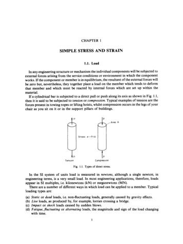
Strain Gage DimensionsStrain Gage DimensionsGage length is an important consideration in strain gage selection, and is usually the first parameter to be defined.Dimensions listed for gage length (as measured inside the grid endloops) and grid width refer to active grid dimensions.Overall length and width refer to the actual foil pattern, not including alignment marks or backing.The matrix size represents the approximate dimensions of the backing/matrix of the gage as shipped. Matrix dimensionsare nominal, with a usual tolerance of 0.015 in ( 0.4 mm). If the gages are encapsulated, the matrix may be smaller byas much as 0.01 in (0.25 mm). Most patterns also include trim marks, and, for use in a restricted area, the backing/matrixmay be field-trimmed on all sides to within 0.01 in (0.25 mm) of the foil pattern without affecting gage HMATRIXLENGTHOVERALLPATTERN WIDTHMATRIX WIDTHDocument No.: 11505Revision: 05-Jan-2016For technical questions, 13
strain gages can be found in the special series of Tech Notes, Tech Tips, and Instruction Bulletins on strain gage technology. Thorough familiarity with these publications will help ensure consistent success in the use of Micro-Measurements strain gages. We also offer ou