Transcription
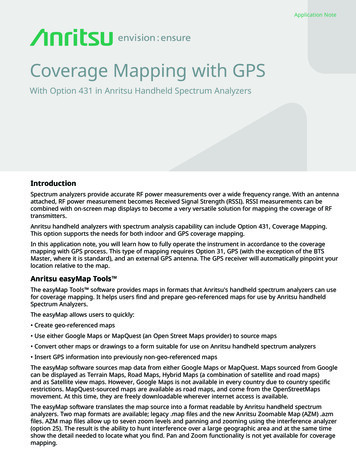
PRODUCT OVERVIEWGPS 4848/100 Galaxy Power System-48V DC Large Power Plant H569-434BenefitsReliability Telecom central office andMTSO applications– Delivers decades of service Streamlined system control andmonitoring– NEBS level 3 certified 20,000 Amp capacity– Industry leading controller features Efficiency approaching 97% Large power applications requiring3-phase input– High availability architectureIntelligence– Ethernet interface for remote access– Centralized network managementInvestment Protection– Backward compatibility– Flexible upgrade options– Seamless integration with ferro plantsOverview595 RectifierOn Time DeliveryThe industry standard for telecom power,the GPS 4848/100 is the first choice tomeet dc power requirements of largecentral office and mobile switchingoffice applications. The Lineage PowerGPS provides output capacities upto 20,000A in an integrated, multicabinet configuration. True 3-phase3-wire rectifiers operate on commercial208/240Vac or 480Vac. The GalaxyMillennium II controller provides detailedsystem management and flexible controlof Lineage and third party equipment.GPS is installed and supported by the mostexperienced services team in the world.The 595LT rectifier integrates proventechnology with superior control featuresin a compact, cost effective solution.This true 3-phase rectifier delivers intrinsicphase balancing and superior powerfactor while lowering installation costs.– Standard building blocksBay OptionsThe system can be deployed incentralized, hybrid, or distributed systemarchitectures. GPS provides industryleading capacity of up to 3,080 Amps in asingle cabinet which can scale to 20,000Amps in a multi-cabinet configuration.A single Millennium II controller linksall components of the system, whileintelligently interacting with the smart grid.08/11 Galaxy Power System 4848– 4 - 6 week availability– 24/7 supportGalaxy Millennium II ControllerThe Galaxy Millennium II controllercombines sophisticated power monitoringand remote management. Thisflagship controller simplifies operationsand maintenance while loweringadministrative costs. Remote peripheralmodules support over 500 monitoringpoints for Lineage or third party devices.Ethernet, SNMP, and TL1 provideintegration with power engineering andNOC workflow. 2011 Lineage Power. All rights reserved.Total EfficiencyThe Lineage Power Total Efficiency (TE) architecture reduces energy lossand lowers cooling costs by 50-70%.TE products will prioritize sustainableenergy sources like solar, wind, waterand fuel cells over traditional utility gridor diesel generator sources – and theywill intelligently respond to smart gridinformation to reduce consumptionduring peak demand periods. ActiveRectifier Management (ARM) andBattery Charging Optimization (BCO)features increase efficiency on currentand legacy power infrastructures. TheTotal Efficiency architecture addressesissues end-to-end based on our provenexperience and expertise in batteries,power distribution, DC energy systems,AC-DC power supplies, and DC-DCboard mounted power to deliver asolution that is more safe, reliable andenergy efficient than alternatives fromour competitors.
T EC H NI C AL SP EC I F I C AT I O NS – G P S 4 8 4 8SpecificationsInputEnvironmental SpecificationsNominal Input Voltage- 595A/LTA- 595B/LTB380 Vac/400 Vac/480 Vac, 3-wire plus ground208 Vac/220 Vac/240 Vac, 3-wire plus groundInput Current- 595A/LTA- 595B/LTB15A @ 480Vac Nominal30A @ 208Vac NominalOperating Temperature0 C to 50 C (32 F to 122 F)Storage Temperature-40 C to 85 C (-40 to 185 F)Operating Relative Humidity5-95% non-condensingInput Frequency Range47-63 HzPower Derating3% per C from 55 C to 65 CAltitude4000M maxInput Voltage Range(per phase-phase):- 595A/LTA- 595B/LTB320 Vac to 530 Vac176 Vac to 260 VacInput Frequency Range47-63 HzMechanicalPower Factor 0.99 at 50% loadTotal Harmonic Distortion 5% at 50% loadHeight (cabinet only)(cabinet with link bus-bar)84.0 in. (2,134 mm) / 72.0 in. (1,829 mm)89.5 in. (2,274 mm)Width (cabinet only)(cabinet with link bus-bar)23.6 in. (600 mm)23.6 in. (600 mm)Depth (cabinet only)(cabinet with link bus-bar)23.6 in. (600 mm)23.6 in. (600 mm)Weight for 84.0” cabinet(approximate)Weight for 72.0” cabinet(approximate)551 lb (250 kg)OutputVoltage Nominal-48 VdcVoltage Adjust Range-44 Vdc to -58 VdcOutput Current(system maximum)20,000ARegulation (line and load range) 0.5%Ripple 100 mVrmsSafety and Standards ComplianceNoise Voiceband 55dBrnCNEBSEvaluated by independent test lab withNRTL status to Telcordia GR63 and GR1089(including level 3 testing)SafetyUL Listed (US and Canada): UL Subject 1801with applicable sections of UL1950/CSA3 950Applicable sections of IEC950/EN60950CE mark meets 72/23/EEC and 93/68/EECdirectivesRoHSCompliant to RoHS EU Directive 2002/95/ECEMCFCC and EN 55022, Class A; FCC, Class AESDEN61000-4-2, Level 4485 lb (220 kg)Architecture SelectionCentralized Architecture vs. DistributedDistributed Architecture: In this system each cabinet contains acdistribution, dc distribution panels, battery connection panels,rectifiers, termination points for load circuits, and a battery shunt.The initial cabinet also contains the system controller and, assuch, it can function as a stand-alone system. The rectifier outputbuses are interconnected to permit cabinets to share current andensure common voltage references for all system rectifiers.Because each cabinet is a self-contained system, the overallsystem capacity can be increased by simply adding cabinet/battery entities. However, growing the system requires a distinct,dedicated floor plan.08/11 Galaxy Power System 4848Centralized Architecture: In a centralized architecture system,each cabinet contains either rectifiers or distribution, but notboth. The separate cabinets are cabled to external busbarswhere a single system shunt is provided to measure total systemload current. The initial cabinet contains ac distribution, rectifiers,the controller, and termination points for the system interconnectcables. Growth cabinets contain ac distribution, rectifiers, andcable termination points. A separate cabinet provides loaddistribution and protection facilities and may include loaddisconnect/reconnect contactors.This architecture requires extensive up-front planning todetermine the ultimate system capacity and engineering to sizethe external busbars appropriately; however, the system plan isnot constrained to dedicated layouts as required for distributedarchitecture systems. 2011 Lineage Power. All rights reserved.Page 2
T EC H NI C AL SP EC I F I C AT I O NS – G P S 4 8 4 8AC Input SpecificationsAC Input RecommendationsFor Group320Nameplate RatingBreaker SizeBreaker QtyConduit Qty & SizeWire Size2 AC Feeds at 80A100A(2) 3-Pole(2) 1 ½”(6) 2 GA2 AC Feeds at 80A100A(2) 3-Pole(1) 2”(6) 1/0 GAGround Wire(2) 6 GA(1) 6 GA3212 AC Feeds at 120A150A(2) 3-Pole(2) 1 ½”(6) 1/0 GA(1) 6 GA3221 AC Feed at 80A100A(1) 3-Pole(1) 1 ½”(3) 2 GA(1) 8 GA3232 AC Feed at 75A90A(2) 3-Pole(1) 1 ½”(6) 2 GA(1) 8 GA4 AC Feeds at 40A50A(4) 3-Pole(2) 1 ½”(12) 6 GA(2) 8 GA4 AC Feeds at 40A50A(4) 3-Pole(4) ¾”(12) 8 GA(4) 8 GA6 AC Feeds at 40A50A(6) 3-Pole(2) 1 ½”(18) 6 GA(2) 8 GA6 AC Feeds at 40A50A(6) 3-Pole(6) ¾”(18) 8 GA(6) 8 GA4 AC Feeds at 20A25A(4) 3-Pole(1) 1 ½”(12) 8 GA(1) 8 GA4 AC Feeds at 20A30A(4) 3-Pole(1) 1 ½”(12) 6 GA(1) 8 GA4 AC Feeds at 20A25A(4) 3-Pole(2) ¾”(12) 10 GA(2) 8 GA4 AC Feeds at 20A30A(4) 3-Pole(2) ¾”(12) 10 GA(2) 8 GA6 AC Feeds at 20A25A(6) 3-Pole(1) 1 ½”(18) 8 GA(1) 8 GA6 AC Feeds at 20A30A(6) 3-Pole(1) 2”(18) 6 GA(1) 8 GA6 AC Feeds at 20A25A(6) 3-Pole(2) 1”(18) 10 GA(2) 8 GA6 AC Feeds at 20A30A(6) 3-Pole(2) 1 ½”(18) 8 GA(2) 8 GA6 AC Feeds at 20A25A or 30A(6) 3-Pole(6) ¾”(18) 10 GA(6) 8 GA12 AC Feeds at 20A25A(12) 3-Pole(2) 1 ½”(36) 8 GA(2) 8 GA12 AC Feeds at 20A30A(12) 3-Pole(2) 2”(36) 6 GA(2) 8 GA12 AC Feeds at 20A25A(12) 3-Pole(4) ¾”(36) 10 GA(4) 8 GA12 AC Feeds at 20A30A(12) 3-Pole(4) 1 ½”(36) 8 GA(4) 8 GA12 AC Feeds at 20A25A(12) 3-Pole(6) ¾”(36) 10 GA(6) 8 GA12 AC Feeds at 40A50A(12) 3-Pole(6) 1”(36) 6 GA(6) 8 GA12 AC Feeds at 40A50A(12) 3-Pole(4) 1 ½”(36) 4 GA(4) 8 GA8 AC Feeds at 20A25A(8) 3-Pole(2) 1 ½”(24) 8 GA(2) 8 GA8 AC Feeds at 20A30A(8) 3-Pole(2) 1 ½”(24) 6 GA(2) 8 GA8 AC Feeds at 20A25A(8) 3-Pole(4) ¾”(24) 10 GA(4) 8 GA8 AC Feeds at 20A30A(8) 3-Pole(4) ¾”(24) 10 GA(4) 8 GA8 AC Feeds at 40A50A(8) 3-Pole(2) 1 ½”(1) 1”(24) 6 GA(3) 8 GA8 AC Feeds at 40A50A(8) 3-Pole(4) 1”(24) 6 GA(4) 8 GA8 AC Feeds at 40A50A(8) 3-Pole(8) ¾”(24) 8 GA(8) 8 GA14 AC Feeds at 20A25A(14) 3-Pole(2) 1 ½”(42) 8 GA(2) 8 GA14 AC Feeds at 20A30A(14) 3-Pole(2) 2”(42) 6 GA(2) 8 GA14 AC Feeds at 20A25A(14) 3-Pole(5) 1”(42) 10 GA(5) 8 GA14 AC Feeds at 20A30A(14) 3-Pole(4) 1 ½” (1) 1(42) 8 GA(5) 8 GA14 AC Feeds at 20A25A(14) 3-Pole(7) ¾”(42) 10 GA(7) 8 GA14 AC Feeds at 40A50A(14) 3-Pole(7) 1”(42) 6 GA(7) 8 GA4 AC Feeds at 60A70A(4) 3-Pole(2) 1 ½”(12) 4 GA(2) 8 GA4 AC Feeds at 60A70A(4) 3-Pole(4) ¾”(12) 6 GA(4) 8 GA4 AC Feeds at 120A150A(4) 3-Pole(4) 1 ½”(12) 1/0 GA(4) 6 GA324325326327328329330331332333334335Cabinet SpecificationsThermal595LTA595LTB4 Rectifiers2,480W (8,400 BTU / hr)2,600W (8,800 BTU / hr)6 Rectifiers3,730W (12,600 BTU / hr)3,900W (13,200 BTU / hr)8 Rectifiers4,970W 16,800 BTU / hr)5,200W (17,600 BTU / hr)10 Rectifiers6,200W (21,000 BTU / hr)6,500W (22,000 BTU / hr)12 Rectifiers7,450W (25,200 BTU / hr)7,800W (26,400 BTU / hr)14 Rectifiers8,690W (29,400 BTU / hr)9,100W (30,800 BTU / hr)08/11 Galaxy Power System 4848 2011 Lineage Power. All rights reserved.Page 3
O RD ERI NG I NF O RM AT I O N – G P S 4 8 4 8 P O W E R B A Y SStep 1: Select the Power Bays – Distributed Architecture-48V Distributed Architecture Primary (Control) BaysOutputOrdering CodeModel108997516GPS 4848 Distributed Architecture Full Height Control Bay,Millennium II controller, bulk feed 480V AC input for up to six595LTA rectifiers, battery shunt1,320AH569434 G-1, 19, 323, 321089974251,320A880A880A1,760A08/11 Galaxy Power System 4848Vertical DistributionAvailable: 36”6 AC FeedsTerminal StripVertical DistributionAvailable: 45”1 AC Feed4 Circuit BreakersVertical DistributionAvailable: 54”4 AC FeedsTerminal StripVertical DistributionAvailable: 54”8 AC FeedsTerminal StripVertical DistributionAvailable: 54”GPS 4848 Distributed Architecture Full Height Control Bay,Millennium II controller, terminal strip feed 480V AC input forup to four 595LTA rectifiers, battery shuntH569-434 G-1, 19, 326, 32ACC1091261822 AC Feeds6 Circuit BreakersGPS 4848 Distributed Architecture Full Height Control Bay,Millennium II controller, bulk feed 480V AC input for up tofour 595LTA rectifiers, battery shuntH569-434 G-1, 19, 322, 32A108997482PictureGPS 4848 Distributed Architecture Full Height Control Bay,Millennium II controller, terminal strip feed 480V AC input forup to six 595LTA rectifiers, battery shuntH569434 G-1, 19, 327, 32108997524AC InputGPS 4848 Distributed Architecture Full Height Control Bay,Millennium II controller, terminal strip feed 480V AC inputfor up to eight 595LTA rectifiers, battery shuntH596-434 G-1, 19, 330, 32A 2011 Lineage Power. All rights reserved.Page 4
O RD ERI NG I NF O RM AT I O N – G P S 4 8 4 8 P O W E R B A Y SStep 1: Select the Power Bays – Distributed Architecture (cont.)-48V Distributed Architecture Primary (Control) BaysOutputOrdering CodeModelCC109145942GPS 4848 Distributed Architecture Full Height Control Bay,Millennium II controller, bulk feed 208-240V AC input for upto six 595LTB rectifiers, battery shunt1,320AH569434 G-1, 19, 321, 32CC1091500671,320A880A880A1,760A08/11 Galaxy Power System 4848Vertical DistributionAvailable: 36”6 AC FeedsTerminal StripVertical DistributionAvailable: 45”1 AC Feed4 Circuit BreakersVertical DistributionAvailable: 51”4 AC FeedsTerminal StripVertical DistributionAvailable: 54”8 AC FeedsTerminal StripVertical DistributionAvailable: 54”GPS 4848 Distributed Architecture Full Height Control Bay,Millennium II controller, terminal strip feed 208-240V AC inputfor up to four 595LTB rectifiers, battery shuntH569-434 G-1, 19, 324, 32CC1091284842 AC Feeds6 Circuit BreakersGPS 4848 Distributed Architecture Full Height Control Bay,Millennium II controller, bulk feed 208-240V AC input for upto four 595LTB rectifiers, battery shuntH569-434 G-1, 19, 320, 32CC109154588PictureGPS 4848 Distributed Architecture Full Height Control Bay,Millennium II controller, terminal strip feed 208-240V AC inputfor up to six 595LTB rectifiers, battery shuntH569434 G-1, 19, 325, 32CC109154571AC InputGPS 4848 Distributed Architecture Full Height Control Bay,Millennium II controller, terminal strip feed 208-240V ACinput for up to eight 595LTB rectifiers, battery shuntH596-434 G-1, 19, 331, 32A 2011 Lineage Power. All rights reserved.Page 5
O RD ERI NG I NF O RM AT I O N – G P S 4 8 4 8 P O W E R B A Y SStep 1: Select the Power Bays – Distributed Architecture (cont.)-48V Distributed Architecture Supplementary BaysOutputOrdering CodeModel108997508GPS 4848 Distributed Architecture Full Height SupplementalBay, bulk feed 480V AC input for up to six 595LTA rectifiers,battery shunt1,320AH569434 G-1, 18D, 323, 32A1089974331,320A880A880A1,760AVertical DistributionAvailable: 36”6 AC FeedsTerminal StripVertical DistributionAvailable: 45”1 AC Feed4 Circuit BreakersVertical DistributionAvailable: 54”4 AC FeedsTerminal StripVertical DistributionAvailable: 54”8 AC FeedsTerminal StripVertical DistributionAvailable: 54”GPS 4848 Distributed Architecture Full Height SupplementalBay, terminal strip feed 480V AC input for up to four 595LTArectifiers, battery shuntH569-434 G-1, 18D, 326, 32ACC1091261742 AC Feeds6 Circuit BreakersGPS 4848 Distributed Architecture Full Height SupplementalBay, bulk feed 480V AC input for up to four 595LTA rectifiers,battery shuntH569-434 G-1, 18D, 322, 32A108997490PictureGPS 4848 Distributed Architecture Full Height SupplementalBay, terminal strip feed 480V AC input for up to six 595LTArectifiers, battery shuntH569434 G-1, 18D, 327, 32108997532AC InputGPS 4848 Distributed Architecture Full Height SupplementalBay, terminal strip feed 480V AC input for up to eight595LTA rectifiers, battery shuntH596-434 G-1, 18D, 330, 32ANote: All supplemental bays include the interconnect bus bars to connect to an adjacent bay08/11 Galaxy Power System 4848 2011 Lineage Power. All rights reserved.Page 6
O RD ERI NG I NF O RM AT I O N – G P S 4 8 4 8 P O W E R B A Y SStep 1: Select the Power Bays – Distributed Architecture (cont.)-48V Distributed Architecture Supplementary BaysOutputOrdering CodeModelCC109151148GPS 4848 Distributed Architecture Full Height SupplementalBay, bulk feed 208-240V AC input for up to four 595LTBrectifiers, battery shunt880AH569-434 G-1, 18D, 320, 32CC109150075880A1,320A1,320A1,760AVertical DistributionAvailable: 51”4 AC FeedsTerminal StripVertical DistributionAvailable: 54”2 AC Feeds6 Circuit BreakersVertical DistributionAvailable: 36”6 AC FeedsTerminal StripVertical DistributionAvailable: 45”8 AC FeedsTerminal StripVertical DistributionAvailable: 54”GPS 4848 Distributed Architecture Full Height SupplementalBay, terminal strip feed 208-240V AC input for up to six595LTB rectifiers, battery shuntH569434 G-1, 18D, 325, 32CC1091284762 AC Feeds4 Circuit BreakersGPS 4848 Distributed Architecture Full Height SupplementalBay, bulk feed 208-240V AC input for up to six 595LTBrectifiers, battery shuntH569434 G-1, 18D, 321, 32CC109147955PictureGPS 4848 Distributed Architecture Full Height SupplementalBay, terminal strip feed 208-240V AC input for up to four595LTB rectifiers, battery shuntH569-434 G-1, 18D, 324, 32CC109152690AC InputGPS 4848 Distributed Architecture Full Height SupplementalBay, terminal strip feed 208-240V AC input for up to eight595LTB rectifiers, battery shuntH596-434 G-1, 18D, 331, 32ANote: All supplemental bays include the interconnect bus bars to connect to an adjacent bay08/11 Galaxy Power System 4848 2011 Lineage Power. All rights reserved.Page 7
O RD ERI NG I NF O RM AT I O N – G P S 4 8 4 8 P O W E R B A Y SStep 1: Select the Power Bays – Centralized Architecture-48V Centralized Architecture Primary (Control) BaysOutputOrdering CodeModel108994406GPS 4848 Centralized Architecture Full Height Control Bay,Millennium II controller, bulk feed AC breaker panel for 480VAC input for up to 12 595LTA rectifiers2,640AAC Input4 AC Feeds12 Circuit BreakersH569434 G2, 19, 334, 331089943802,640AGPS 4848 Centralized Architecture Full Height Control Bay,Millennium II controller, terminal strip 480 VAC input for up to12 595LTA rectifiers12 AC FeedsTerminal StripH569434 G2, 19, 328, 33CC1091342352,640AGPS 4848 Centralized Architecture Full Height Control Bay,Millennium II controller, bulk feed AC breaker panel for 208VAC input for up to 12 595LTB rectifiers4 AC Feeds12 Circuit BreakersH569434 G2, 19, 335, 33CC1091457772,640AGPS 4848 Centralized Architecture Full Height Control Bay,Millennium II controller, terminal strip 208 VAC input for up to12 595LTB rectifiers12 AC FeedsTerminal StripH569434 G2, 19, 329, 331089827524,800APictureGPS 4848 4800 Amp Centralized Architecture Full HeightControl Bay, distribution onlyVertical Distribution Space: 72.0”Distribution Only BayH569434 G2, 16, 29, 33CC1091676074,800A08/11 Galaxy Power System 4848GPS 4848 4800 Amp Centralized Architecture Full HeightControl WIDE Bay, distribution onlyVertical Distribution Space: 72.0” with ControllerDistribution Only BayH569434 G2, 19, 430, 33 2011 Lineage Power. All rights reserved.Page 8
O RD ERI NG I NF O RM AT I O N – G P S 4 8 4 8 P O W E R B A Y SStep 1: Select the Power Bays – Centralized Architecture (cont.)-48V Centralized Architecture Supplementary BaysOutputOrdering CodeModel108993275GPS 4848 Centralized Architecture Full Height SupplementalRectifier Only Bay, bulk feed 480VAC input for up to 12595LTA rectifiers2,640AAC Input4 AC Feeds12 Circuit BreakersH569-434 G2, 18C, 334, 33CC1091330062,640AGPS 4848 Centralized Architecture Full Height SupplementalRectifier Only Bay, terminal strip 480VAC input for up to 12595LTA rectifiers12 AC FeedsTerminal StripH569-434 G2, 18C, 328, 331089932833,080AGPS 4848 Centralized Architecture Full Height SupplementalRectifier Only Bay, terminal strip 480VAC input for up to 14595LTA rectifiers14 AC FeedsTerminal StripH569-434 G2, 18C, 332, 33CC1091342272,640AGPS 4848 Centralized Architecture Full Height SupplementalRectifier Only Bay, bulk feed 208-240VAC input for up to 12595LTB rectifiers4 AC Feeds12 Circuit BreakersH569-434 G2, 18C, 335, 33CC1091443332,640AGPS 4848 Centralized Architecture Full Height SupplementalRectifier Only Bay, terminal strip 208-240VAC input for up to12 595LTB rectifiers12 AC FeedsTerminal StripH569-434 G2, 18C, 329, 33CC1091366603,080AGPS 4848 Centralized Architecture Full Height SupplementalRectifier Only Bay, terminal strip 208-240VAC input for up to14 595LTB rectifiers14 AC FeedsTerminal StripH569-434 G2, 18C, 333, 331088734154,800APictureGPS 4848 4800 Amp Centralized Architecture Full HeightSupplemental Bay, distribution onlyVertical Distribution Space: 72.0”Distribution Only BayH569434 G2, 12, 29, 33CC1091676154,800A08/11 Galaxy Power System 4848GPS 4848 4800 Amp Centralized Architecture Full HeightSupplemental WIDE Bay, distribution onlyVertical Distribution Space: 72.0”, No ControllerDistribution Only BayH569434 G2, 18C, 430, 33 2011 Lineage Power. All rights reserved.Page 9
O RD ERI NG I NF O RM AT I O N - G P S 4 8 4 8 R E C TI FI E R SStep 2: Select RectifiersRectifiersOutputOrdering Code108979238220AModelPicture220 amp, 48VDC output, 480VAC 3 Ph input Rectifier595LTA108990405220A220 amp, 48VDC output, 208VAC 3 Ph input Rectifier595LTB108994686595LT Filler bracket and keying kit for LT on single rectifier shelfCC848809178595LT Filler bracket for dual shelf, use when one 595LT rectifer isinstalled on shelf (one included with each bay with LT shelves)Ordering Code84869358608/11 Galaxy Power System 4848ModelSpare Rectifier Fan Assembly [(2) required for each rectifier] 2011 Lineage Power. All rights reserved.Page 10
O RD ERI NG I NF O RM AT I O N - D I SI T RI BU T I O N P A N E L SStep 3: Select Field Installed Distribution PanelsField Installed Distribution PanelsOrdering CodePanel DescriptionVertical Space (in.)Internal Return Bars (Dist Arch Only)1089714741089713186 Position 125A-800A Circuit Breaker Panel121089080703 Position 125A-600A Circuit Breaker Panel61089080701089714175 Position 125A-800A Circuit Breaker Panel910890807010897153210 Position 3A-100A Bullet Breaker Panel610890810410897168014 Position 3A-200A Bullet Breaker Panel610890810410898767822 Position 3A-200A Bullet Breaker Panel910890810410897087210 Position 3A-60A TPS Fuse Panel61089081041089867465 Position 70A-225A TPL-B Fuse Panel9108908070CC1091331132 Position 70A-600A TPL Fuse Panel61089080701089852356 Position 1A-15A GMT Fuse Panel0NA108908278Low Voltage Load Disconnect Option108908070Return Bus for panels in like shaded lines108908104Return Bus for panels in like shades linesDistribution panels with Ground Return includedOrdering CodePanel DescriptionVertical Space (in.)Internal Return Bars (Dist Arch Only)1089714666 Position 125A-800A Circuit Breaker Panel12G431089712923 Position 125A-600A Circuit Breaker Panel6G421089714095 Position 125A-800A Circuit Breaker Panel9G48CC1091331052 Position 70A-600A Fuse Panel6G59406628222Fuse holder for 70-250A fuses in G59--1089867385 Position 70A-225A Fuse Panel9G5410897086410 Position 3A-100A Bullet Breaker Panel6G9610897167214 Position 3A-200A Bullet Breaker Panel6G9710898768622 Position 3A-200A Bullet Breaker Panel9G981089852356 Position GMT holder up to 15A0G5808/11 Galaxy Power System 4848 2011 Lineage Power. All rights reserved.Page 11
ORDERING INFORMATION – COMPONENTSStep 4: Select Distribution ComponentsNote: Plug in, and bolt in distribution components are listed below.These must be selected to match the distribution panels selected in Step 4.Bullet Style Load Circuit BreakersOrdering #AmperageCB Positions (Poles)Min Wire 23660164079982447012407998251801 ( 1 vacant)2407998269901 ( 1 14792-pole adapter bus kit (includes bus for ¼” hole lug on 5/8” centers andhardware), order one per breaker8487456623-pole adapter bus kit (includes bus for 5/16” hole lug on 1” centers andhardware), order one per breaker08/11 Galaxy Power System 4848 2011 Lineage Power. All rights reserved.PhotoPage 12
ORDERING INFORMATION – COMPONENTSStep 4: Select Distribution Components (cont.)Note: Plug in, and bolt in distribution components are listed below.These must be selected to match the distribution panels selected in Step 4.Large Circuit Breaker KitsOrdering #AmperageCB Positions (Poles)Min Wire 10890820322514/010890821130022 x 4/010890823740022 x 4/010890822950033 x 4/010890825260033 x 4/010898478280044 x 4/008/11 Galaxy Power System 4848 2011 Lineage Power. All rights reserved.PhotoPage 13
ORDERING INFORMATION – COMPONENTSStep 4: Select Distribution Components (cont.)Note: Plug in, and bolt in distribution components are listed below.These must be selected to match the distribution panels selected in Step 4.Bullet Style Fuse Holder and TPS FusesOrdering #AmperageWP-92461 ListMin Wire .18 Alarm Fuse408548944Bullet Fuse Holder, TFD-101-011-09 (Alarms on Blown Fuse or Fuse Head Removal)CC408617410Bullet Fuse Holder, TFD-101-011-10 (Alarms on Blown Fuse Only)PhotoGMT 0A40647395915A40851582308/11 Galaxy Power System 4848Fuse Puller 2011 Lineage Power. All rights reserved.Page 14
ORDERING INFORMATION – COMPONENTSStep 4: Select Distribution Components (cont.)Note: Plug in, and bolt in distribution components are listed below.These must be selected to match the distribution panels selected in Step 4.Large TPL FusesOrdering #Amperage408472322Max # wires per positionMin Wire GagePhoto70-250A Fuse Holder Head(only required for 2 Position 70A-600A TPL Fuse Panel)4023289260.18A Alarm 2534/040679484225034/040679486730032 x 4/040679487540032 x 4/040679488350032 x 4/040679489160033 x 4/008/11 Galaxy Power System 4848 2011 Lineage Power. All rights reserved.Page 15
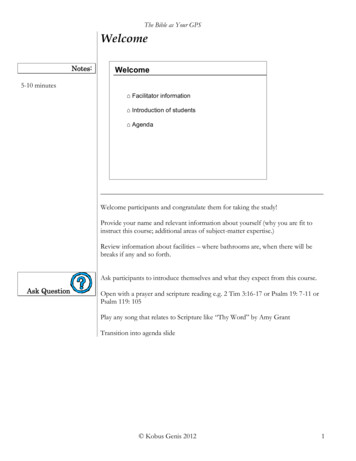
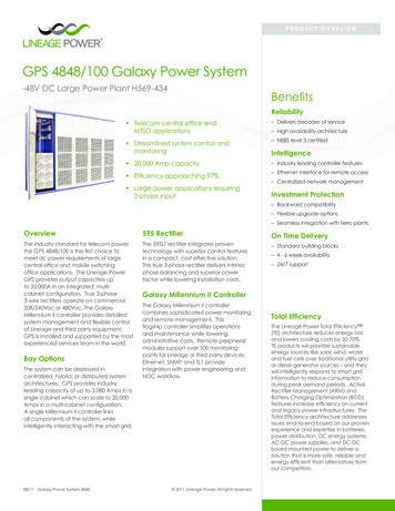
ORDERING INFORMATION – MONITORING OPTIONSStep 5: Select Remote Peripheral Monitoring OptionsOrdering #DescriptionPhoto# Inputs# Temp108469461ModulesJ85501G1L21 RPM Shunt Monitoring (221F)61108469479J85501G1L22 RPM Voltage 0-200VDC (221D)61108469495J85501G1L23 RPM Transducers (221J)61108298431J85501G1L24 RPM Voltage 0-3VDC (221A)61108298498J85501G1L25 RPM Voltage 0-16VDC (221B)61108469503J85501G1L26 RPM Voltage 0-70VDC (221C)61108298449J85501G1L27 RPM Binary (222A)61108483538J85501G1L28 RPM Temperature (223T)07108298456J85501G1L9 RPM Control Relay (214A)30Supporting Material407377704Connecting Cable for RPMs (Order by foot)848535332Blue panel for mounting 6 modules above a GPS cabinet848412367White panel for mounting 6 modules in a 23-inch frame inside GPS bay84730741012’ Cable to be used with Temperature Probes847917879½” Diameter Ring Terminal Temperature Probe (Cable Required)8485288815/16” Diameter Ring Terminal Temperature Probe (Cable Required)405298308Termination Resistor (1 per bus)406712968Ferrite Bead (1 per bus)403607955Monitor Channel cable KS13385 22AWG stranded pair, R&Bk(order by the foot)10898447723” grey panel, 6 RPM mounting panel for Lorain plantsMillennium Remote MonitoringMillennium IIIntelligentController2 loops through 406712968 ferrite beadprior to termination onto Millennium IITB1 6/8 (7 shield)Bus 1Up to 300 Meters Each Bus(980 Ft.Max.)Up to 85 Remote ModulesUp to 6 Points Each Module(Up to 510 Points)1TB20022 AWG has a 300 ft. max. one waycable length between Remote Moduleand monitored point. Order 403607955 by the foot.407377704 20 AWG 2conductor standedW/ground shielded wire.EngineAlternatorPlant 1DistributionPlant 1BatteriesDenotes Remote Monitoring ModulesACDistributionDenotes Last Remote Monitoring Module on bus.A 560 ohm, 10 watt Terminating Resistor isrequired for proper operation.08/11 Galaxy Power System 4848 2011 Lineage Power. All rights reserved.Plant 2BatteriesPage 16
Step 6: Select Optional AC Monitoring EquipmentAC Monitoring OptionsOrdering CodeDescriptionPhotoConfigured PanelsCC4086460053P/3W 208/240V Line to Line, 10x12x14 box provides current, voltage, and powerCC4086460463P/3W 480V Line to Line, 10x12x14 box provides current, voltage, and powerCC4086460543P/4W 208V Line to Neutral, 10x12x14 box provides current, voltage, and powerTransducersCC4086458081-phase AC Current Transducer (Built-in CT; 150A max current; 350 kcmil maxconductor size)CC4086458161-phase AC Voltage Transducer 120VCC4086458241-phase AC Voltage Transducer 208/240VCC4086445373-phase AC Voltage Transducer 208/240V Line to LineCC4086457413-phase AC Voltage Transducer 208/240V Line to Neutral (120V)CC4086458323-phase AC Voltage Transducer 480V Line to LineCC4086458403-phase AC Current TransducerCurrent Transformers (Required for configured panels and current transducers)CC408645857Current Transformer, 200A primary, 5A secondary, 4 in inside diameter408524862Current Transformer, 400A primary, 5A secondary, 4 in inside diameterCC408645865Current Transformer, 600A primary, 5A secondary, 6 in inside diameterCC408645873Current Transformer, 800A primary, 5A secondary, 6 in inside diameterCC408645881Current Transformer, 1000A primary, 5A secondary, 8 in inside diameterCC408645898Current Transformer, 1200A primary, 5A secondary, 8 in inside diameterMiscellaneousCC408645907Barrier terminal block to extend the CT secondary leads beyond their 12 ft factory length.Use 12 AWG THHN wire in conduit.CC408645915Bud Industries Wall Box (12H x 10W x 8D) w/captive screw cover & internal mounting panel.For mounting transducers08/11 Galaxy Power System 4848 2011 Lineage Power. All rights reserved.Page 17
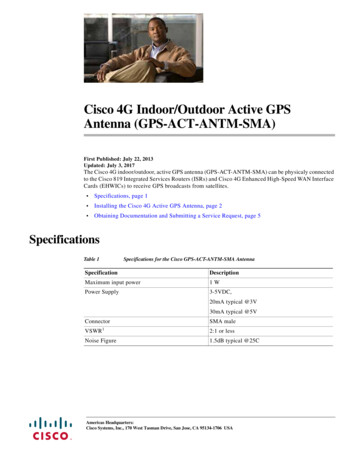
ORDERING INFORMATION – BATTERY TERMINATIONStep 7: Select Battery Termination OptionsDistributed ArchitectureOrdering #Description848285847Optional bus bar that provides 16 output terminations. (Two required and provided with each rectifier-only cabinet))848385878Optional adapter that allows two lugs to be stacked and connected at one location. (Provides one adapter)CC848769570Optional bus bar that provides 10 output terminations spaced specifically for 750 MCM wide barrel terminations.(Two required per cabinet)350 kcmil max if usingadjacent hole sets with848285847 bus bar4/0 AWG max08/11 Galaxy Power System 4848 2011 Lineage Power. All rights reserved.Page 18
ORDERING INFORMATION – RETURN BUS BARSStep 8: Select Distributed Return Bus BarsDistributed ArchitectureOrdering #DescriptionCC848805160External Return Bus Kit for Mounting on Distributed Architecture Cabinets, 1 per cabinetOnly required if internal return bus bars were not ordered in Step 3. The external return bus kit is an alternative to internal return buses when many largecables are required.Please contact Lineage Power for additional options for external return bus bars.08/11 Galaxy Power System 4848 2011 Lineage Power. All rights reserved.Page 19
ORDERING INFORMATION – RETURN BUS BARSStep 9: Select Centralized Return Bus BarsCentralized ArchitectureOrdering #Description108298472ED8301950G9 2600A Ground Bar arranged for mounting on auxiliary framing, or 20 or 25 inch ladder-type cable rack109006080ED8301950G
380 Vac/400 Vac/480 Vac, 3-wire plus ground 208 Vac/220 Vac/240 Vac, 3-wire plus ground Input Current - 595A/LTA - 595B/LTB 15A @ 480Vac Nominal 30A @ 208Vac Nominal Input Voltage Range (per phase-phase): - 595A/LTA - 595B/LTB 320 Vac to 530 Vac 176 Vac to 260 Vac Input Frequency Range 47-63 Hz Power Factor 0.99 at 50% load