Transcription
Installation Note for the CWDM PassiveOptical SystemProduct Numbers: CWDM-GBIC-1470 , CWDM-GBIC-1490 , CWDM-GBIC-1510 ,CWDM-GBIC-1530 , CWDM-GBIC-1550 , CWDM-GBIC-1570 , CWDM-GBIC-1590 ,CWDM-GBIC-1610 , OADM-MUX-4 , CWDM-MUX-8 , CWDM-MUX-AD-1470 ,CWDM-MUX-AD-1490 , CWDM-MUX-AD-1510 , CWDM-MUX-AD-1530 ,CWDM-MUX-AD-1550 , CWDM-MUX-AD-1570 , CWDM-MUX-AD-1590 ,CWDM-MUX-AD-1610 , CWDM-CHASSIS-2 This installation note provides the technical specifications and installation instructions for the CoarseWave Division Multiplexer (CWDM) passive optical system.ContentsThis installation note contains the following sections: Overview, page 2 Safety Overview, page 5 Hardware Requirements, page 7 Required Tools, page 7 Installing the CWDM Passive Optical System, page 8 Specifications, page 16 Related Documentation, page 17 Obtaining Documentation, page 17 Obtaining Technical Assistance, page 18Corporate Headquarters:Cisco Systems, Inc., 170 West Tasman Drive, San Jose, CA 95134-1706 USACopyright 2002. Cisco Systems, Inc. All rights reserved.78-14167-01
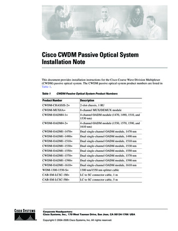
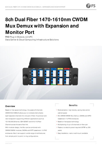
OverviewOverviewThe CWDM passive optical system provides optical networking support for high-speed datacommunication for metropolitan area networks (MANs) over a grid of eight CWDM opticalwavelengths in both ring or point-to-point configurations.You connect your multiplexed/demultiplexed wavelengths and added/dropped channels to CWDMGBICs installed in your network switches.The CWDM passive optical system includes the following components: CWDM system shelf CWDM plug-in modules CWDM GBICsYou install your CWDM OADM and multiplexer/demultiplexer (Mux/Demux) plug-in modules in yourCWDM system shelf. Install CWDM GBICs in your Catalyst 4000 and 6000 family switches to connectthem to your plug-in modules. A CWDM GBIC is a hot-swappable input/output device that links yourswitching module to the CWDM passive optical system using a pair of single-mode fiber-optic cables.CWDM System ShelfThe CWDM system shelf (CWDM-CHASSIS-2) is a standard 19-inch chassis that is one rack unit (RU)in height. Install the CWDM system shelf in the same equipment rack as your switch or in an adjacentrack so that you can connect the CWDM plug-in modules to the CWDM GBICs in your switch.The CWDM system shelf has two slots. You install CWDM OADM modules or Mux/Demux plug-inmodules in the slots.CWDM OADM and Mux/Demux Plug-In ModulesThe CWDM OADM and Mux/Demux plug-in modules are installed in the CWDM system shelf. Youconnect the CWDM OADM and Mux/Demux plug-in modules to CWDM GBICs that are installed inyour switching modules.The CWDM OADM is a scalable passive optical multiplexer/demultiplexer that adds or drops twoCWDM channels of the same wavelength from network traffic and allows all other wavelengths to passstraight through. The CWDM OADM maps each of the two added/ dropped channels into separatesingle pair fiber paths traveling in opposite directions:”east” and “west.”The CWDM Mux/Demux plug-in modules multiplex and demultiplex four or eight CWDM channels(wavelengths) from a single-mode fiber-optic cable. The four-channel CWDM Mux/Demux modulepasses straight through four of the eight wavelengths. You can create point-to-point, hub-and-spoke, andring networks using the CWDM Mux/Demux plug-in modules. Connect your CWDM Mux/Demuxplug-in module to CWDM GBICs of equivalent wavelengths that are installed in your switches.Figure 1 shows the front panel of the CWDM four-channel Mux/Demux plug-in module. Figure 2shows the CWDM eight-channel Mux/Demux plug-in module. Figure 3 through 10 show the plug-inmodules for each of the available longwave spectrums. The plug-in module ports are color-coded to helpwith installation. Each of the colors indicates the wavelength of the port. For more information aboutthe color codes, see the “Connecting the CWDM Passive Optical System to Your Switch” section onpage 11.Installation Note for the CWDM Passive Optical System278-14167-01
OverviewFigure 1CWDM Four-Channel Plug-In Module (CWDM-MUX-4) Front PanelCISCO 1000BASE-CWDM1590155015101470PASSRXINVISIBLE LASERDO NOT VIEWFigure 268846RXTXNETWORKTXCWDMMUX- 4CWDM Eight-Channel Mux/Demux Plug-In Module (CWDM-MUX-8) Front PanelCISCO 1000BASE-CWDMINVISIBLE LASERDO NOT VIEWFigure WDMMUX-8Longwave 1470 nm Laser Single-Mode Plug-In Module Front PanelCISCO 1000BASE-CWDMEASTRXINVISIBLE LASERDO NOT VIEWFigure ETWORKTXCWDM-MUXAD-1470Longwave 1490 nm Laser Single-Mode Plug-In Module Front PanelCISCO 1000BASE-CWDMEASTRXINVISIBLE LASERDO NOT VIEWFigure ETWORKTXCWDM-MUXAD-1490Longwave 1510 nm Laser Single-Mode Plug-In Module Front PanelCISCO 1000BASE-CWDMEASTRXINVISIBLE LASERDO NOT NETWORKTXCWDM-MUXAD-1510Installation Note for the CWDM Passive Optical System78-14167-013
OverviewFigure 6Longwave 1530 nm Laser Single-Mode Plug-In Module Front PanelCISCO 1000BASE-CWDMEASTRXINVISIBLE LASERDO NOT VIEWFigure ETWORKTXCWDM-MUXAD-1530Longwave 1550 nm Laser Single-Mode Plug-In Module Front PanelCISCO 1000BASE-CWDMRXINVISIBLE LASERDO NOT VIEWFigure mRXNETWORKTXCWDM-MUXAD-1550Longwave 1570 nm Laser Single-Mode Plug-In Module Front PanelCISCO 1000BASE-CWDMRXINVISIBLE LASERDO NOT VIEWFigure 9Longwave 1590 nm Laser Single-Mode Plug-In Module Front PanelFigure 10Longwave 1610 nm Laser Single-Mode Plug-In Module Front T1570nmNETWORKTXCWDM-MUXAD-1570Installation Note for the CWDM Passive Optical System478-14167-01
Safety OverviewSafety OverviewThroughout this publication, safety warnings appear in procedures that, if performed incorrectly, canharm you. A warning symbol precedes each warning statement.WarningThis warning symbol means danger. You are in a situation that could cause bodily injury.Before you work on any equipment, be aware of the hazards involved with electricalcircuitry and be familiar with standard practices for preventing accidents. To seetranslations of the warnings that appear in this publication, refer to the RegulatoryCompliance and Safety Information document that accompanied this device.WarningWaarschuwingDit waarschuwingssymbool betekent gevaar. U verkeert in een situatiedie lichamelijk letsel kan veroorzaken. Voordat u aan enige apparatuur gaat werken,dient u zich bewust te zijn van de bij elektrische schakelingen betrokken risico's endient u op de hoogte te zijn van standaard maatregelen om ongelukken te voorkomen.Voor vertalingen van de waarschuwingen die in deze publicatie verschijnen, kunt u hetdocument Regulatory Compliance and Safety Information (Informatie over naleving vanveiligheids- en andere voorschriften) raadplegen dat bij dit toestel is ingesloten.WarningVaroitusTämä varoitusmerkki merkitsee vaaraa. Olet tilanteessa, joka voi johtaaruumiinvammaan. Ennen kuin työskentelet minkään laitteiston parissa, ota selvääsähkökytkentöihin liittyvistä vaaroista ja tavanomaisista onnettomuuksienehkäisykeinoista. Tässä julkaisussa esiintyvien varoitusten käännökset löydät laitteenmukana olevasta Regulatory Compliance and Safety Information -kirjasesta(määräysten noudattaminen ja tietoa turvallisuudesta).WarningAttentionCe symbole d'avertissement indique un danger. Vous vous trouvez dans unesituation pouvant causer des blessures ou des dommages corporels. Avant de travaillersur un équipement, soyez conscient des dangers posés par les circuits électriques etfamiliarisez-vous avec les procédures couramment utilisées pour éviter les accidents.Pour prendre connaissance des traductions d’avertissements figurant dans cettepublication, consultez le document Regulatory Compliance and Safety Information(Conformité aux règlements et consignes de sécurité) qui accompagne cet appareil.WarningWarnungDieses Warnsymbol bedeutet Gefahr. Sie befinden sich in einer Situation, diezu einer Körperverletzung führen könnte. Bevor Sie mit der Arbeit an irgendeinem Gerätbeginnen, seien Sie sich der mit elektrischen Stromkreisen verbundenen Gefahren undder Standardpraktiken zur Vermeidung von Unfällen bewußt. Übersetzungen der indieser Veröffentlichung enthaltenen Warnhinweise finden Sie im Dokument RegulatoryCompliance and Safety Information (Informationen zu behördlichen Vorschriften undSicherheit), das zusammen mit diesem Gerät geliefert wurde.Installation Note for the CWDM Passive Optical System78-14167-015
Safety OverviewWarningAvvertenzaQuesto simbolo di avvertenza indica un pericolo. La situazione potrebbecausare infortuni alle persone. Prima di lavorare su qualsiasi apparecchiatura, occorreconoscere i pericoli relativi ai circuiti elettrici ed essere al corrente delle pratichestandard per la prevenzione di incidenti. La traduzione delle avvertenze riportate inquesta pubblicazione si trova nel documento Regulatory Compliance and SafetyInformation (Conformità alle norme e informazioni sulla sicurezza) che accompagnaquesto dispositivo.WarningAdvarselDette varselsymbolet betyr fare. Du befinner deg i en situasjon som kan føre tilpersonskade. Før du utfører arbeid på utstyr, må du vare oppmerksom på defaremomentene som elektriske kretser innebærer, samt gjøre deg kjent med vanligpraksis når det gjelder å unngå ulykker. Hvis du vil se oversettelser av deadvarslenesom finnes i denne publikasjonen, kan du se i dokumentet Regulatory Compliance andSafety Information (Overholdelse av forskrifter og sikkerhetsinformasjon) som blelevert med denne enheten.WarningAvisoEste símbolo de aviso indica perigo. Encontra-se numa situação que lhe poderácausar danos físicos. Antes de começar a trabalhar com qualquer equipamento,familiarize-se com os perigos relacionados com circuitos eléctricos, e com quaisquerpráticas comuns que possam prevenir possíveis acidentes. Para ver as traduções dosavisos que constam desta publicação, consulte o documento Regulatory Complianceand Safety Information (Informação de Segurança e Disposições Reguladoras) queacompanha este dispositivo.Warning¡Advertencia!Este símbolo de aviso significa peligro. Existe riesgo para su integridadfísica. Antes de manipular cualquier equipo, considerar los riesgos que entraña lacorriente eléctrica y familiarizarse con los procedimientos estándar de prevención deaccidentes. Para ver una traducción de las advertencias que aparecen en estapublicación, consultar el documento titulado Regulatory Compliance and SafetyInformation (Información sobre seguridad y conformidad con las disposicionesreglamentarias) que se acompaña con este dispositivo.WarningVarning!Denna varningssymbol signalerar fara. Du befinner dig i en situation som kanleda till personskada. Innan du utför arbete på någon utrustning måste du varamedvetenom farorna med elkretsar och känna till vanligt förfarande för att förebygga skador. Seförklaringar av de varningar som förkommer i denna publikation i dokumentetRegulatory Compliance and Safety Information (Efterrättelse av föreskrifter ochsäkerhetsinformation), vilket medföljer denna anordning.WarningOnly trained and qualified personnel should be allowed to install or replace thisequipment.Installation Note for the CWDM Passive Optical System678-14167-01
Hardware RequirementsWarningBefore you install, operate, or service the system, read the Site Preparation and SafetyGuide. This guide contains important safety information you should know beforeworking with the system.WarningOnly trained and qualified personnel should be allowed to install, replace, or servicethis equipment.WarningClass 1 laser product.WarningBecause invisible laser radiation may be emitted from the aperture of the port when nocable is connected, avoid exposure to laser radiation and do not stare into openapertures.WarningUltimate disposal of this product should be handled according to all national laws andregulations.WarningDuring this procedure, wear grounding wrist straps to avoid ESD damage to the card. Donot directly touch the backplane with your hand or any metal tool, or you could shockyourself.Hardware RequirementsYou can use the CWDM passive optical system with Catalyst 4000 and 6000 family switches. Usesingle-mode fiber-optic cable with SC connectors to connect the CWDM passive optical system to yourswitches.Required ToolsWarningDuring this procedure, wear grounding wrist straps to avoid ESD damage to the card. Donot directly touch the backplane with your hand or any metal tool, or you could shockyourself.You will need these tools to install the CWDM passive optical system: Wrist strap or other grounding device Antistatic mat or antistatic foam Number 1 and number 2 Phillips screwdrivers for the captive installation screws on most modules 3/16-inch flat-blade screwdriver for captive installation screwsInstallation Note for the CWDM Passive Optical System78-14167-017
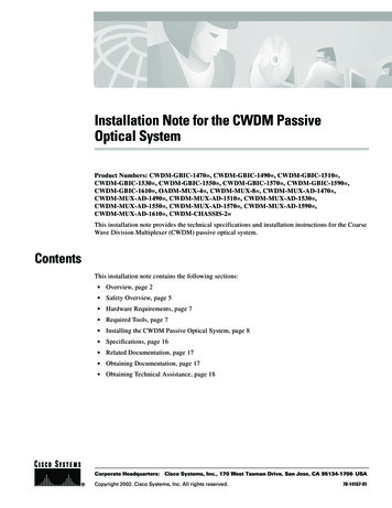
Installing the CWDM Passive Optical SystemInstalling the CWDM Passive Optical SystemThe CWDM passive optical system includes the system shelf, CWDM OADM plug-in modules,CWDM Mux/Demux plug-in modules, and CWDM GBICs.You must first install the system shelf, then the CWDM OADM and CWDM Mux/Demux plug-inmodules, followed by the CWDM GBICs you want to install. The following sections provide theinstallation procedures for each of these components: Installing the System Shelf, page 8 Installing the CWDM OADM and Mux/Demux Plug-In Modules, page 9 Removing a CWDM OADM or Mux/Demux Plug-In Module, page 9 Installing, Removing, and Maintaining CWDM GBICs, page 10 Connecting the CWDM Passive Optical System to Your Switch, page 11Installing the System ShelfNoteEnsure that you install the CWDM system shelf in the same rack or an adjacent rack toyour Catalyst 4000 family switch so that you can connect all the cables between yourCWDM plug-in modules and the CWDM GBICs in your switch.Follow these steps to mount the system shelf on an equipment rack:Step 1Align the mounting holes in the L brackets with the mounting holes in the equipment rack.Step 2Secure the system shelf using four (two per side) 12-24 x 3/4-inch screws through the elongated holesin the L bracket and into the threaded holes in the mounting post. (See Figure 11.)Mounting the System Shelf on the Rack68818Figure 11Installation Note for the CWDM Passive Optical System878-14167-01
Installing the CWDM Passive Optical SystemStep 3Use a tape measure and level to ensure that the system shelf is mounted straight and level.Installing the CWDM OADM and Mux/Demux Plug-In ModulesPerform the following steps to install your CWDM OADM or Mux/Demux plug-in modules:Step 1Loosen the captive screws on the blank plug-in module faceplate and remove the faceplate.Step 2Align the plug-in module with the slot on the system shelf as shown in Figure 12.Installing a CWDM Mux/Demux Plug-In Module68819Figure 12Step 3Gently push the plug-in module into the system shelf slot. Ensure that you line up the captive screwson the plug-in module with the screw holes on the shelf.Step 4Tighten the captive screws.Removing a CWDM OADM or Mux/Demux Plug-In ModuleTo remove a CWDM OADM or Mux/Demux plug-in module, perform the following steps:Step 1Loosen the captive screws on each side of the plug-in module using a screwdriver.Step 2Gently pull on both captive screws to release the plug-in module from the shelf.Step 3Pull the plug-in module out of the shelf.Step 4Replace the blank plug-in module faceplate if you do not intend to install another plug-in module.Installation Note for the CWDM Passive Optical System78-14167-019
Installing the CWDM Passive Optical SystemInstalling, Removing, and Maintaining CWDM GBICsThis section provides installation, removal, and maintenance guidelines for your CWDM GBICs.Installing a CWDM GBICTo install a CWDM GBIC, follow these steps:Step 1Remove the CWDM GBIC from its protective packaging.Step 2Verify that the CWDM GBIC is the correct model for your network configuration (see Table 1).Table 1Step 3CWDM GBICsModel NumberCWDM GBIC WavelengthCWDM-GBIC-1470 Longwave 1470 nm laser single-modeCWDM-GBIC-1490 Longwave 1490 nm laser single-modeCWDM-GBIC-1510 Longwave 1510 nm laser single-modeCWDM-GBIC-1530 Longwave 1530 nm laser single-modeCWDM-GBIC-1550 Longwave 1550 nm laser single-modeCWDM-GBIC-1570 Longwave 1570 nm laser single-modeCWDM-GBIC-1590 Longwave 1590 nm laser single-modeCWDM-GBIC-1610 Longwave 1610 nm laser single-modeRemove the dust covers from the CWDM GBIC’s optical bores as shown in Figure 13.CWDM GBIC68802Figure 13Step 4Grasp the sides of the CWDM GBIC with your thumb and forefinger.Step 5Insert the CWDM GBIC into a GBIC slot on your switching module. You should hear a click when theGBIC has been properly seated into the slot.Installation Note for the CWDM Passive Optical System1078-14167-01
Installing the CWDM Passive Optical SystemRemoving GBICsThis section describes how to remove CWDM GBICs from a supervisor engine or switching module.WarningBecause invisible radiation may be emitted from the aperture of the port when no fibercable is connected, avoid exposure to radiation and do not stare into open apertures.To remove a CWDM GBIC, follow these steps:Step 1Disconnect the fiber-optic cable from the CWDM GBIC SC-type connector.Step 2Release the CWDM GBIC from the slot by simultaneously squeezing the plastic tabs (one on each sideof the CWDM GBIC).Step 3Pull the CWDM GBIC out of the slot.Step 4Install the plug in the CWDM GBIC optical bores and place the CWDM GBIC in protective packaging.GBIC Maintenance GuidelinesFollow these GBIC maintenance guidelines: GBICs are static sensitive. To prevent ESD damage, follow the usual board and componenthandling procedures. GBICs are dust sensitive. When the GBIC is stored or when a fiber-optic cable is not plugged in,always keep plugs in the GBIC optical bores. The most common source of contaminants in the optical bores is debris that collects on the ferrulesof the optical connectors. Use an alcohol swab or Kim-Wipe to clean the ferrules of the opticalconnector.Connecting the CWDM Passive Optical System to Your SwitchUse the CWDM passive optical system connector color codes shown inTable 2 to help you connect yourCWDM passive optical system to your switch.Table 2CWDM Passive Optical System Connector Color CodesColorConnector (Wavelength) DescriptionsGrayLongwave 1470 nm laser single-modeVioletLongwave 1490 nm laser single-modeBlueLongwave 1510 nm laser single-modeGreenLongwave 1530 nm laser single-modeYellowLongwave 1550 nm laser single-modeOrangeLongwave 1570 nm laser single-modeRedLongwave 1590 nm laser single-modeBrownLongwave 1610 nm laser single-modeInstallation Note for the CWDM Passive Optical System78-14167-0111
Installing the CWDM Passive Optical SystemSee Figure 1 through 10 for the plug-in module front panels. See Table 1 for the CWDM GBIC partnumbers and descriptions.Connecting Cables to a CWDM OADM Plug-In ModuleTo connect the CWDM OADM plug-in module to your network, perform these steps while referring toFigure 14:Step 1Insert the CWDM GBICs into the appropriate connectors on your switch if you have not already doneso. For more information, see the “Installing a CWDM GBIC” section on page 10.Step 2Insert the CWDM GBICs (color code/wavelength specific) into their respective switching moduleGBIC ports.NoteConnect CWDM OADM and Mux/Demux ports to CWDM GBICs of the equivalentwavelength to ensure that the system operates correctly.Step 3Clean all fiber-optic connectors on the cabling before inserting them into the four-channel CWDMMux/Demux connectors.Step 4Connect the single-mode fiber-optic cable from the CWDM GBIC (TX/RX) to the OADM moduleequipment connectors (TX/RX).NoteConnect TX to RX ports and RX to TX ports to ensure that the system operates correctly.Step 5If you are using both channels of the CWDM OADM plug-in module than repeat Step 4 for the secondchannel.Step 6Connect the West backbone single-mode fiber-optic cable to the OADM Network West connector andconnect the East backbone single-mode fiber-optic cable to the OADM Network East connector.Installation Note for the CWDM Passive Optical System1278-14167-01
Installing the CWDM Passive Optical SystemFigure 14Cabling a CWDM OADM Plug-In HIS ASSEMBLYCONTAINSELECTROSTATISENSITCIVE cting Cables to a CWDM Four-Channel Plug-In ModuleTo connect a CWDM four-channel Mux/Demux plug-in module to your network, perform these stepswhile referring to Figure 15:Step 1Insert the CWDM GBICs into the appropriate connectors on your switch if you have not already doneso. For more information, see the “Installing a CWDM GBIC” section on page 10.Step 2Insert the CWDM GBICs (color code/wavelength specific) into their respective switching moduleGBIC ports.NoteConnect CWDM OADM and Mux/Demux ports to CWDM GBICs of the equivalentwavelength to ensure that the system operates correctly.Step 3Clean all fiber-optic connectors on the cabling before inserting them into the four-channel CWDMMux/Demux connectors.Step 4Connect the single-mode fiber-optic cables from the CWDM GBICs (TX/RX; up to four channels) tothe OADM module equipment connectors (TX/RX; up to four wavelengths, including 1470nm,1510nm, 1550nm, 1590nm).Installation Note for the CWDM Passive Optical System78-14167-0113
Installing the CWDM Passive Optical SystemNoteStep 5Connect TX to RX ports and RX to TX ports to ensure that the system operates correctly.Connect the one backbone single-mode fiber-optic cable to the OADM Network connector andconnect the other backbone single-mode fiber-optic cable to the OADM Pass connector.Figure 15Cabling a CWDM Four-Channel Mux/Demux Plug-In ModulePowerSupply1PowerSupply2PowerCAUTIONTHIS ASSEMBLYCONTAINSELECTROSTATISENSITCIVE 13Connecting Cables to a CWDM Eight-Channel Mux/DemuxTo connect your switch to a CWDM eight-channel Mux/Demux plug-in module, perform these stepswhile referring to Figure 16:Step 1Insert CWDM GBICs (color code/wavelength specific) into their respective switches.Step 2Clean all fiber-optic connectors on the cabling before inserting them into the eight-channel CWDMMux/Demux connectors.NoteStep 3Connect CWDM OADM and Mux/Demux ports to CWDM GBICs of the equivalentwavelength to ensure that the system operates correctly.Connect the single pair fiber-optic cables from the CWDM GBICs (TX/RX; up to eight channels) tothe OADM module equipment connectors (TX/RX; up to eight wavelengths)Installation Note for the CWDM Passive Optical System1478-14167-01
Installing the CWDM Passive Optical SystemStep 4Connect the backbone single pair fiber-optic cable to the OADM Network connector.Step 5Connect the fiber-optic cables from the CWDM GBIC (TX/RX) to the CWDM eight-channelMux/Demux (TX/RX) connectors.NoteConnect TX to RX ports and RX to TX ports to ensure that the system operates correctly.Figure 16Cabling an CWDM Eight-Channel Mux/Demux ModulePowerSupply1PowerSupply2PowerCAUTIONTHIS ASSEMBLYCONTAINSELECTROSTATISENSITCIVE 13Installation Note for the CWDM Passive Optical System78-14167-0115
SpecificationsSpecificationsTable 3 lists the specifications for the CWDM OADM plug-in module. Table 4 lists the specificationsfor the CWDM mux/demux plug-in modules.Table 3CWDM OADM Plug-In Module SpecificationsItemSpecificationPhysical CharacteristicsDimensions8.35 x 1.75 x 8.7 in. (212 x 44 x 221 mm)Weight1.5 lbs. (0.68 kg)ConnectorsEquipmentTwo dual SC-type connectorsSwitchDual SC-type connectorsEnvironmentalOperating temperature32 to 140 ºF (0 to 60ºC)Storage temperature-40 to 185ºF (–40 to 85ºC)Typical Insertion LossTX equipment to RX network (add) 1.5 dBRX equipment to TX network (drop) 2.0 dBPass Through (Network to Network) 1.5 dBIsolation and DirectivityIsolation 45 dBDirectivity –55 dBTable 4CWDM Mux/Demux Plug-In Module SpecificationsItemSpecificationPhysical CharacteristicsDimensions8.35 x 1.75 x 8.7 in. (212 x 44 x 221 mm)Weight1.5 lbs. (0.68 kg)ConnectorsEquipmentEight dual SC-type connectorsSwitchDual SC-type connectorsEnvironmentalOperating temperature32 to 140 ºF (0 to 60ºC)Storage temperature-40 to 185ºF (–40 to 85ºC)Typical Insertion LossTX equipment to RX network 4.0 dBRX equipment to TX network 4.0 dBInstallation Note for the CWDM Passive Optical System1678-14167-01
Related DocumentationTable 4CWDM Mux/Demux Plug-In Module Specifications (continued)ItemSpecificationIsolation and DirectivityIsolationMux: 15 dBDemux: 45 dBDirectivity –55 dBRelated DocumentationFor more detailed installation and configuration information, refer to these publications: Regulatory Compliance and Safety Information for the Catalyst 4000 Family Switches Regulatory Compliance and Safety Information for the Catalyst 6000 Family Switches Site Preparation and Safety Guide Catalyst 4000 Family Installation Guide Catalyst 4000 Family Module Installation Guide Catalyst 4000 Family Supervisor Engines and Switching Modules Installation Note Catalyst 6000 Family Installation Guide Catalyst 6000 Family Module Installation Guide Software Configuration Guide—Catalyst 4000 Family, Catalyst 2948G, and Catalyst 2980GSwitches Command Reference—Catalyst 4000 Family, Catalyst 2948G, and Catalyst 2980G Switches System Message Guide—Catalyst 6000 Family, Catalyst 5000 Family, Catalyst 4000 Family,Catalyst 2926G Series, Catalyst 2948G, and Catalyst 2980G Switches Layer 3 Services Software Configuration Guide—Catalyst 5000 Family, Catalyst 4000 Family,Catalyst 2926G Series, Catalyst 2948G, and Catalyst 2980G Switches Catalyst 4000 Family Supervisor Engines and Switching Modules Installation NoteObtaining DocumentationThe following sections explain how to obtain documentation from Cisco Systems.World Wide WebYou can access the most current Cisco documentation on the World Wide Web at the following URL:http://www.cisco.comTranslated documentation is available at the following URL:http://www.cisco.com/public/countries languages.shtmlInstallation Note for the CWDM Passive Optical System78-14167-0117
Obtaining Technical AssistanceDocumentation CD-ROMCisco documentation and additional literature are available in a Cisco Documentation CD-ROMpackage, which is shipped with your product. The Documentation CD-ROM is updated monthly andmay be more current than printed documentation. The CD-ROM package is available as a single unit orthrough an annual subscription.Ordering DocumentationCisco documentation is available in the following ways: Registered Cisco Direct Customers can order Cisco product documentation from the NetworkingProducts er root.pl Registered Cisco.com users can order the Documentation CD-ROM through the onlineSubscription Store:http://www.cisco.com/go/subscription Nonregistered Cisco.com users can order documentation through a local account representative bycalling Cisco corporate headquarters (California, USA) at 408 526-7208 or, elsewhere in NorthAmerica, by calling 800 553-NETS (6387).Documentation FeedbackIf you are reading Cisco product documentation on Cisco.com, you can submit technical commentselectronically. Click Leave Feedback at the bottom of the Cisco Documentation home page. After youcomplete the form, print it out and fax it to Cisco at 408 527-0730.You can e-mail your comments to bug-doc@cisco.com.To submit your comments by mail, use the response card behind the front cover of your document, orwrite to the following address:Cisco SystemsAttn: Document Resource Connection170 West Tasman DriveSan Jose, CA 95134-9883We appreciate your comments.Obtaining Technical AssistanceCisco provides Cisco.com as a starting point for all technical assistance. Customers and partners canobtain documentation, troubleshooting tips, and sample configurations from online tools by using theCisco Technical Assistance Center (TAC) Web Site. Cisco.com registered users have complete accessto the technical support resources on the Cisco TAC Web Site.Installation Note for the CWDM Passive Optical System1878-14167-01
Obtaining Technical AssistanceCisco.comCisco.com is the foundation of a suite of interactive, networked services that provides immediate, openaccess to Cisco information, networking solutions, services, programs, and resources at any time, fromanywhere in the world.Cisco.com is a highly integrated Internet application and a powerful, easy-to-use tool that provides abroad range of features and services to help you to Streamline business processes and improve productivity Resolve technical issues with online support Download and test software packages Order Cisco learning materials and merchandise Register for online skill assessment, training, and certification programsYou can self-register on Cisco.com to obtain customized information and service. To access Cisco.com,go to the following URL:http://www.cisco.comTechnical Assistance CenterThe Cisco TAC is available to all customers who need technical assistance with a Cisco product,technology, or solution. Two types of support are available through the Cisco TAC: the Cisco TACWeb Site and the Cisco TAC Escalation Center.Inquiries to Cisco TAC are categorized according to the urgency of the issue: Priority level 4 (P4)—You need information or assistance concerning Cisco product capabilities,product installation, or basic product configuration. Priority level 3 (P3)—Your network performance is degraded. Network functionality is noticeablyimpaired, but most business operations continue. Priority level 2 (P2)—Your production network is severely degraded, affecting significant aspectsof business operations. No worka
CISCO 1000BASE-CWDM 68840 NETWORK CWDM-MUX-AD-1570 1570nm RX RX RX RX TX TX TX TX WEST EQUIPMENT EAST EQUIPMENT NET INVISIBLE LASER DO NOT VIEW. 5 Installation Note for the CWDM Passive Optical System 78-14167-01 Safety Overview Safety Overview Throughout this publication, safety warnings appear in procedures that, if performed incorrectly, can