Transcription
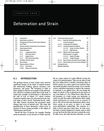
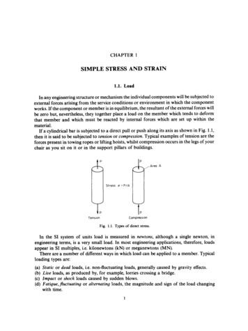
V I S H A Y m i c r o - m e as u r e m e n t sStrain Gages and InstrumentsTech Note TN-515Strain Gage Rosettes:Selection, Application and Data Reduction1.0 IntroductionA strain gage rosette is, by definition, an arrangementof two or more closely positioned gage grids, separatelyoriented to measure the normal strains along differentdirections in the underlying surface of the test part.Rosettes are designed to perform a very practical andimportant function in experimental stress analysis. It canbe shown that for the not-uncommon case of the generalbiaxial stress state, with the principal directions unknown,three independent strain measurements (in differentdirections) are required to determine the principal strainsand stresses. And even when the principal directions areknown in advance, two independent strain measurementsare needed to obtain the principal strains and stresses.requirements. They are also offered in a number of gagelengths, noting that the gage length specified for a rosetterefers to the active length of each individual grid withinthe rosette. As illustrated in Figure 2, rectangular anddelta rosettes may appear in any of several geometricallydifferent, but functionally equivalent, forms. Guidancein choosing the most suitable rosette for a particularapplication is provided in Section 2.0, where selectionconsiderations are reviewed.RectangularTo meet the foregoing requirements, the Vishay MicroMeasurements Division manufactures three basic types ofstrain gage rosettes (each in a variety of forms): Tee: two mutually perpendicular grids. 45 -Rectangular: three grids, with the second andthird grids angularly displaced from the first grid by45 and 90 , respectively.Delta 60 -Delta: three grids, with the second and third grids60 and 120 away, respectively, from the first grid.Representative gage patterns for the three rosette types arereproduced in Figure 1.In common with single-element strain gages, rosettesare manufactured from different combinations of gridalloy and backing material to meet varying application5X(b)5X(c)Figure 1 – Basic rosette types, classified by grid orientation: (a) tee; (b) 45º-rectangular; (c) 60º delta.Revision 25-Mar-08For technical support, om151Tech Note5X(a)Figure 2 – Geometrically different, but functionallyequivalent configurations of rectangular and delta rosettes.
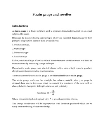
Tech Note TN-515Vishay Micro-MeasurementsStrain Gage Rosettes: Selection, Application and Data ReductionSince biaxial stress states occur very commonly in machineparts and structural members, it might be presumed thathalf or so of the strain gages used in experimental stressanalysis would be rosettes. This does not seem to be thecase, however, and ten percent (or less) rosette usage may bemore nearly representative. To what degree this pattern ofusage reflects an inclination for on-site makeup of rosettesfrom single-element gages, or simply an undue tendency toassume uniaxiality of the stress state, is an open question.At any rate, neither practice can generally be recommendedfor the accurate determination of principal strains.It must be appreciated that while the use of a straingage rosette is, in many cases, a necessary conditionfor obtaining the principal strains, it is not a sufficientcondition for doing so accurately. Knowledgeability inthe selection and application of rosettes is critical to theirsuccessful use in experimental stress analysis; and theinformation contained in this Tech Note is intended to helpthe user obtain reliably accurate principal strain data.2.0 Rosette Selection ConsiderationsTech NoteA comprehensive guide for use in selecting Vishay MicroMeasurements strain gages is provided in Reference 1. Thispublication should first be consulted for recommendationson the strain-sensitive alloy, backing material, selftemperature-compensation number, gage length, andother strain gage characteristics suitable to the expectedapplication. In addition to basic parameters such as theforegoing, which must be considered in the selection of anystrain gage, two other parameters are important in rosetteselection. These are: (1) the rosette type — tee, rectangular,or delta; and (2) the rosette construction — planar (singleplane) or stacked (layered).The tee rosette should be used only when the principal straindirections are known in advance from other considerations.Cylindrical pressure vessels and shafts in torsion are twoclassical examples of the latter condition. However, caremust be exercised in all such cases that extraneous stresses(bending, axial stress, etc.) are not present, since thesewill affect the directions of the principal axes. Attentionmust also be given to nearby geometric irregularities,such as holes, ribs, or shoulders, which can locally alterthe principal directions. The error magnitudes due tomisalignment of a tee rosette from the principal axes aregiven in Reference 2. As a rule, if there is uncertainty aboutthe principal directions, a three-element rectangular ordelta rosette is preferable. When necessary (and, using theproper data-reduction relationships), the tee rosette can beinstalled with its axes at any precisely known angle from theprincipal axes; but greatest accuracy will be achieved byalignment along the principal directions. In the latter case,except for the readily corrected error due to transversesensitivity, the two gage elements in the rosette indicate thecorresponding principal strains directly.www.vishaymg.com152Where the directions of the principal strains are unknown,a three-element rectangular or delta rosette is alwaysrequired; and the rosette can be installed without regardto orientation. The data-reduction relationships given inSection 4.0 yield not only the principal strains, but also thedirections for the principal axes relative to the referencegrid (Grid 1) of the rosette. Functionally, there is littlechoice between the rectangular and delta rosettes. Becausethe gage axes in the delta rosette have the maximumpossible uniform angular separation (effectively 120 ), thisrosette is presumed to produce the optimum sampling ofthe underlying strain distribution. Rectangular rosetteshave historically been the more popular of the two,primarily because the data-reduction relationships aresomewhat simpler. Currently, however, with the widespreadaccess to computers and programmable calculators, thecomputational advantage of the rectangular rosette isof little consequence. As a result of the foregoing, thechoice between rectangular and delta rosettes is moreapt to be based on practical application considerationssuch as availability from stock, compatibility with thespace available for installation, convenience of solder tabarrangement, etc.All three types of rosettes (tee, rectangular, and delta)are manufactured in both planar and stacked versions.As indicated (for the rectangular rosette) in Figure 3, thePlanarStackedFigure 3 – Rectangular rosettes (of the same gagelength) in planar and stacked construction.For technical support, contactmicro-measurements@vishay.comDocument Number: 11065Revision 25-Mar-08
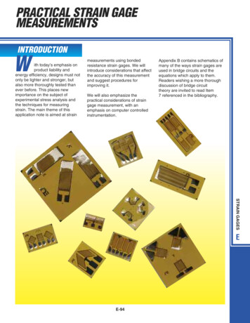
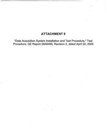
Tech Note TN-515Vishay Micro-MeasurementsStrain Gage Rosettes: Selection, Application and Data Reductionplanar rosette is etched from the strain-sensitive foil asan entity, with all gage elements lying in a single plane.The stacked rosette is manufactured by assembling andlaminating two or three properly oriented single-elementgages. When strain gradients in the plane of the test partsurface are not too severe, the normal selection is theplanar rosette. This form of rosette offers the followingadvantages in such cases: Thin and flexible, with greater conformability tocurved surfaces; Minimal reinforcing effect; Superior heat dissipation to the test part; Available in all standard forms of gage construction,and generally accepts all standard optional features; Optimal stability; Maximum freedom in leadwire routing andattachment.The principal disadvantages of the planar rosette arise fromthe larger surface area covered by the sensitive portion ofthe gage. When the space available for gage installationis small, a stacked rosette may fit, although a planar onewill not. More importantly, where a steep strain gradientexists in the surface plane of the test part, the individualgage elements in a planar rosette may sense different strainfields and magnitudes. For a given active gage length, thestacked rosette occupies the least possible area, and hasthe centroids (geometric centers) of all grids lying overthe same point on the test part surface. Thus, the stackedrosette more nearly approaches measurement of the strainsat a point. Although normally a trivial consideration, itcan also be noted that all gages in a stacked rosette havethe same gage factor and transverse sensitivity, whilethe grids in a planar rosette will differ slightly in theseproperties, due to their different orientations relative to therolling direction of the strain-sensitive foil. The technicaldata sheet accompanying the rosettes fully documents theseparate properties of the individual grids.Document Number: 11065Revision 25-Mar-08“Numbering”, as used here, refers to the numeric (oralphabetic) sequence in which the gage elements in arosette are identified during strain measurement, andfor substitution of measured strains into data-reductionrelationships such as those given in Section 4.0. Contrary to awidely held impression, the subject of gage numbering is notnecessarily a trivial matter. It is, in fact, basic to the proper,and complete, interpretation of rosette measurement.3With any three-element rosette, misinterpretation of therotational sequence (CW or CCW), for instance, can leadto incorrect principal strain directions. In the case of therectangular rosette, an improper numbering order willproduce completely erroneous principal strain magnitudes,as well as directions. These errors occur when the gageuser’s numbering sequence differs from that employed inthe derivation of the data-reduction relationships.To obtain correct results using the data-reductionrelationships provided in Section 4.0 (and in the Appendix),the grids in three-element rosettes must be numbered ina particular way. It is always necessary in a rectangularrosette, for instance, that grid numbers 1 and 3 be assigned totwo mutually perpendicular grids. Any other arrangementwill produce incorrect principal strains. Following arethe general rules for proper rosette numbering. With arectangular rosette, the axis of Grid 2 must be 45 awayfrom that of Grid 1; and Grid 3 must be 90 deg away, in thesame rotational direction. Similarly, with a delta rosette,the axes of Grids 2 and 3 must be 60 and 120 away,respectively, in the same direction from Grid 1.In principle, the preceding rules could be implementedby numbering the grids in either the clockwise orcounterclockwise direction, as long as the sequenceis correct. Counterclockwise numbering is preferable,however, because it is consistent with the usual engineeringpractice of denoting counterclockwise angular measurement as positive in sign. The gage grids in all Vishay MicroMeasurements general-purpose, three-element planarrosettes (rectangular and delta) are numerically identified,and numbered in the counterclockwise direction.*Examples of the grid numbering for several representativerosette types are illustrated in Figure 4. At first glimpse, itmight appear that gage patterns (b) and (c) are numberedclockwise instead of counterclockwise. But when thesepatterns are examined more closely, and when the axisof Grid 2 is transposed across the grid-circle diameter tosatisfy the foregoing numbering rules, it can be seen thatthe rosette numbering is counterclockwise in every case.* V ishay Micro-Measurements also supplies special-purposeplanar rectangular rosettes designed exclusively for use withthe hole-drilling method of residual stress analysis. Sincethese rosettes require different data-reduction relationships,procedures, and interpretation, they are numbered clockwise todistinguish them from general-purpose rosettes.For technical support, om153Tech NoteIt should be realized, however, that the stacked rosetteis noticeably stiffer and less conformable than its planarcounterpart. Also, because the heat conduction paths forthe upper grids in a stacked rosette are much longer, the heatdissipation problem may be more critical when the rosetteis installed on a material with low thermal conductivity.Taking into account their poorer heat dissipation and theirgreater reinforcement effects, stacked rosettes may not bethe best choice for use on plastics and other nonmetallicmaterials. A stacked rosette can also give erroneous strainindications when applied to thin specimen in bending, sincethe grid plane of the uppermost gage in a three-gage stackmay be as much as 0.0045 in [0.11 mm] above the specimensurface. In short, the stacked rosette should ordinarilybe reserved for applications in which the requirement forminimum surface area dictates its selection.3.0 Gage Element Numbering
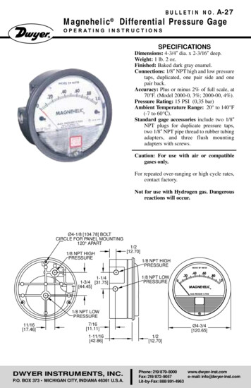
Tech Note TN-515Vishay Micro-MeasurementsStrain Gage Rosettes: Selection, Application and Data Reduction(a)Figure 4 – Counterclockwise numbering of gridsin Vishay Micro-Measurements general-purposestrain gage rosettes (see text).Vishay Micro-Measurements stacked rosettes are notnumbered, as a matter of manufacturing economics. Theuser should number the gages in stacked rosettes accordingto the rules given here and illustrated in Figures 2 and 4.4.0 Principal Strains and Directionsfrom Rosette MeasurementsThe equations for calculating principal strains from threerosette strain measurements are derived from what isknown as a “strain-transformation” relationship. Asemployed here in its simplest form, such a relationshipexpresses the normal strain in any direction on a testsurface in terms of the two principal strains and the anglefrom the principal axis to the direction of the specifiedstrain. This situation can be envisioned most readily withthe aid of the well-known Mohr’s circle for strain, as shownin Figure 5**. It can be seen from Figure 5a (noting that theangles in Mohr’s circle are double the physical angles onthe test surface) that the normal strain at any angle θ fromthe major principal axis is simply expressed by:Tech Noteεθ ε P εQ ε P – εQ cos 2θ22(b)(1)(c)** T he Mohr’s circle in Figure 5 is constructed with positive shearstrain plotted downward. This is done so that the positiverotational direction in Mohr’s circle is the same (CCW) asfor the rosette, while maintaining the usual sign conventionfor shear (i.e., positive shear corresonds to a reduction in theinitial right angle at the origin of the X-Y axes as labeled inFigure 5b).www.vishaymg.com154Figure 5 – Strain transformation from the principal strains tothe strain in any direction: (a) εθ in terms of principal strains εP,and εQ, as shown by Mohr’s circle for strain; (b) rectangularrosette installed on a test surface, with Grid 1 at thearbitrary angle θ from the major principal axis; (c) axes of therectangular rosette superimposed on Mohr’s circle for strain.For technical support, contactmicro-measurements@vishay.comDocument Number: 11065Revision 25-Mar-08
Tech Note TN-515Vishay Micro-MeasurementsStrain Gage Rosettes: Selection, Application and Data ReductionFigure 5b represents a small area of the test surface, witha rectangular rosette installed, and with the reference grid(#1) oriented at θ degrees from εp. Mohr’s circle, with theaxes of the rosette superimposed, is shown in Figure 5c.By successively substituting into Equation (1) the angles forthe three grid directions, the strain sensed by each grid canbe expressed as follows:ε1 ε P εQ ε P – εQ cos 2θ22ε2 ε P εQ ε P – εQ cos 2 θ 45o22(ε P εQ ε P – εQε3 cos 2 θ 90o22((2a))(2b) 2ε – ε ε 1φP ,Q –θ tan –1 2 1 3 2 ε1 – ε 3 (5)The physical direction of the acute angle given by eitherEquation (4) or Equation (5) is always counterclockwiseif positive, and clockwise if negative. The only differenceis that θ is measured from the principal axis to Grid 1,while ϕ is measured from Grid 1 to the principal axis.Unfortunately, since tan 2ϕ tan 2(ϕ 90 ), the calculatedangle can refer to either principal axis; and hence theidentification in Equation (5) as ϕP,Q. This ambiguitycan readily be resolved (for the rectangular rosette) byapplication of the following simple rules:(a) if ε1 ε3, then ϕP,Q ϕP)(2c)(b) if ε1 ε3, then ϕP,Q ϕQ(c) if ε1 ε3 and ε2 ε1, then ϕP,Q ϕP –45º(d) if ε1 ε3 and ε2 ε1, then ϕP,Q ϕP 45ºWhen the rosette is installed on a test part subjected toan arbitrary strain state, the variables on the right-handside of Equations (2) are unknown. But the strains ε1, ε2and ε 3 can be measured. Thus, by solving Equations (2)simultaneously for the unknown quantities εP, εQ, and θ,the principal strains and angle can be expressed in terms ofthe three measured strains. Following is the result of thisprocedure:ε P ,Qε ε1 1 3 22θ (ε1 – ε 2 ) (ε 2 – ε3 ) ε – 2ε 2 ε3 1tan –1 12 ε1 – ε3 22(3)(4)The reasoning which underlies the preceding rules becomesobvious when a sketch is made of the corresponding Mohr’scircle for strain, and the rosette axes are superimposed asin Figure 5c. A similar technique for assuring correctinterpretation of the angle is given in the form of a step-bystep algorithm in Reference 3.The preceding development has been applied to therectangular rosette, but the same procedure can be usedto derive corresponding data-reduction equations for thedelta rosette shown in Figure 6. When grid angles θ, θ 60 , and θ 120 are successively substituted into Equation(1), the resulting three equations can again be solvedsimultaneously for the principal strains and angle. Thus,for the delta rosette:ε1 ε 2 ε32 33ε P ,Q θ 3 (ε3 – ε 2 ) 1tan –1 2 2ε1 – ε 2 – ε3 (6)(7)As in the case of Equation (4), the angle θ calculated fromEquation (7) refers to the angular displacement of Grid 1from the principal axis. The sense of the angle can again bechanged by reversing its sign to give the angle from Grid 1to a principal axis:φP ,Q –θ Document Number: 11065Revision 25-Mar-08(ε1 – ε 2 )2 (ε 2 – ε3 )2 (ε3 – ε1 )2 3 (ε 2 – ε3 ) 1tan –1 2 2ε1 – ε 2 – ε3 For technical support, g.com155Tech NoteIf the rosette is properly numbered, the principal strainscan be calculated from Equation (3) by substituting themeasured strains for ε1, ε2 and ε3. The plus and minusalternatives in Equation (3) yield the algebraicallymaximum and minimum principal strains, respectively.Unambiguous determination of the principal angle fromEquation (4) requires, however, some interpretation, asdescribed in the following. To begin with, the angle θrepresents the acute angle from the principal axis to thereference grid of the rosette, as indicated in Figure 5. In thepractice of experimental stress analysis, it is somewhat moreconvenient, and easier to visualize, if this is reexpressedas the angle from Grid 1 to the principal axis. To changethe sense of the angle requires only reversing the sign ofEquation (4). Thus:(e) i f ε1 ε2 ε3, then ϕP,Q is indeterminate (equalbiaxial strain).
Tech Note TN-515Vishay Micro-MeasurementsStrain Gage Rosettes: Selection, Application and Data Reduction(a)(a) if ε1 ε 2 ε3, then φP ,Q φP2(b) if ε1 ε 2 ε3, then φP ,Q φQ2(c) if ε1 ε 2 ε3, and ε 2 ε1, then φP ,Q φP 45o2(d) if ε1 ε 2 ε3, and ε 2 ε1, then φP ,Q φP 45o2(3) if ε1 ε 2 ε3 then φP ,Q is indeterminate(equal biaxial strain)When the principal angle is calculated automatically bycomputer from Equation (5) or Equation (8), it is alwaysnecessary of course, to avoid the condition of division byzero if ε1 ε3 with a rectangular rosette, or ε1 (ε2 ε3)/2with a delta rosette. For this reason, the computer shouldbe programmed to perform the foregoing (c) and (d) tests,in each case, prior to calculating the arc-tangent.Once the principal strains have been determined fromEquation (3) or Equation (6), the strain state in the surfaceof the test part is completely defined. If desired, themaximum shear strain can be obtained directly from:γ MAX εP – εQ(b)Tech NoteFigure 6 – Delta rosette: (a) installed on a test surface,with Grid 1 at the angle of θ from the major principal straindirection; (b) rosette grid axes superimposed on Mohr’scircle for strain. Note that Grid 2 is to be viewed as 60º(CCW) from Grid 1 in the rosette, and 120º in Mohr’s circle.In every case [Equations (4), (5), (7), and (8)], the anglesare to be interpreted as counterclockwise if positive, andclockwise if negative.Equation (8) embodies the same ambiguity with respect tothe tan 2ϕ and tan 2(ϕ 90 ) as Equation (5). As before, theambiguity can easily be resolved (for the delta rosette) byconsidering the relative magnitudes (algebraically) amongthe individual strain measurements; namely:www.vishaymg.com156(9)Intuitive understanding of the strain state can also beenhanced by sketching the corresponding Mohr’s circle,approximately to scale. In Equations (3) and (6), the firstterm represents, in each case, the distance from the originto the center of the circle, and the second term representsthe radius, or γMAX/2. With the angle ϕ calculated, furtherinsight can be gained by superimposing the rosette gridaxes on the Mohr’s circle, as in Figures 5c and 6b.5.0 Principal Stresses from Principal StrainsAs previously noted, a three-element strain gage rosettemust be employed to determine the principal strains ina general biaxial stress state when the directions of theprincipal axes are unknown. The usual goal of experimentalstress analysis, however, is to arrive at the principal stresses,for comparison with some criterion of failure. With thestrain state fully established as described in Section 4.0,the complete state of stress (in the surface of the test part)can also be obtained quite easily when the test materialmeets certain requirements on its mechanical properties.Since some types of strain gage instrumentation, such asFor technical support, contactmicro-measurements@vishay.comDocument Number: 11065Revision 25-Mar-08
Tech Note TN-515Vishay Micro-MeasurementsStrain Gage Rosettes: Selection, Application and Data Reductionour System 6000, calculate both the principal strains andthe principal stresses, the following material is provided asbackground information.If the test material is homogeneous in composition, and isisotropic in its mechanical properties (i.e., the propertiesare the same in every direction), and if the stress/strainrelationship is linear, with stress proportional to strain,then the biaxial form of Hooke’s law can be used to convertthe principal strains into principal stresses. This procedurerequires, of course, that the elastic modulus (E ) andPoisson’s ratio (ν ) of the material be known. Hooke’s lawfor the biaxial stress state can be expressed as follows:()(10a)()(10b)σP Eε P νεQ1– ν2σQ EεQ νε P1– ν2The numerical values of the principal strains calculatedform Equation (3) or Equation (6) can be substituted intoequations (10), along with the elastic properties, to obtainthe principal stresses. As an alternative, Equation (3)or Equation (6) depending on the rosette type) can besubstituted algebraically into Equations (10) to express theprincipal stresses directly in terms of the three measuredstrains and the material properties. The results are asfollows:Rectangular:σ P ,Q E ε1 ε32 2 1– ν1 ν (ε1 – ε 2 )2 (ε 2 – ε3 )2 (11)Delta: ε1 ε 2 ε3 E 1– ν σ P ,Q 3 222 2ε–ε ε–ε ε–ε()()()122331 1 ν (12)Document Number: 11065Revision 25-Mar-086.0 Errors, Corrections, and LimitationsThe obvious aim of experimental stress analysis is todetermine the significant stresses in a test object as accuratelyas necessary to assure product reliability under expectedservice conditions. As demonstrated in the precedingsections of this Tech Note, the process of obtaining theprincipal stresses involves three basic, and sequential, steps:(1) measurement of surface strains with a strain gage rosette;(2) transformation of measured strains to principal strains;and (3) conversion of principal strains to principal stresses.Each step in this procedure has its own characteristic errorsources and limits of applicability; and the stress analystmust carefully consider these to avoid potentially seriouserrors in the resulting principal stresses.Of first importance is that the measured strains be as freeas possible of error. Strain measurements with rosettesare subject, of course, to the same errors (thermal output,transverse sensitivity, leadwire resistance effects, etc.) asthose with single-element strain gages. Thus, the samecontrolling and/or corrective measures are required toobtain accurate data. For instance, signal attenuationdue to leadwire resistance should be eliminated by shuntcalibration 4 , or by numerically correcting the straindata for the calculated attenuation, based on the knownresistances of the leadwires and strain gages.Because at least one of the gage grids in any rosette will inevery case be subjected to a transverse strain which is equalto or greater than the strain along the grid axis, considerationshould always be given to the transverse-sensitivity errorwhen performing rosette data reduction. The magnitude ofthe error in any particular case depends on the transversesensitivity coefficient (K t) of the gage grid, and on theratio of the principal strains (εP / εQ ). In general, whenKt 1%, the transverse-sensitivity error is small enough to beignored. However, at larger values of Kt, depending on therequired measurement accuracy, correction for transversesensitivity may be necessary. Detailed procedures, as wellas correction equations for all cases and all rosette types,are given in Reference 5.When strain measurements must be made in a variablethermal environment, the thermal output of the strain gagecan produce rather large errors, unless the instrumentationcan be zero-balanced at the testing temperature, understrain-free conditions. In addition, the gage factor of thestrain gage changes slightly with temperature. Reference6 provides a thorough treatment of errors due to thermaleffects in strain gages, including specific compensation andcorrection techniques for minimizing these errors.After making certain that strain measurement errors suchFor technical support, om157Tech NoteWhen the test material is isotropic and linear-elastic inits mechanical properties (as required for the validity ofthe preceding strain-to-stress conversion), the principalstress axes coincide in direction with the principal strains.Because of this, the angle from Grid 1 of the rosette tothe principal stress direction is given by Equation (5)for rectangular rosettes, and by Equation (8) for deltarosettes.
Tech Note TN-515Vishay Micro-MeasurementsStrain Gage Rosettes: Selection, Application and Data Reductionas the foregoing have been eliminated or controlled to thedegree feasible, attention can next be given to possibleerrors in the strain-transformation procedure for obtainingthe principal strains. A potentially serious source of errorcan be created when the user attempts to make up a rosetteon the specimen from three conventional single-elementgages. The error is caused by misalignment of the individualgages within the rosette. If, for example, the second andthird gages in a rectangular rosette configuration are notaccurately oriented at 45 and 90 , respectively, from thefirst gage, the calculated principal strains will be in error.The magnitude of the error depends, of course, on themagnitude (and direction) of the misalignment; but italso depends on the principal strain ratio, εP /εQ, and onthe overall orientation of the rosette with respect to theprincipal axes. For certain combinations of principal strainratio and rosette orientation, 5-degree alignment errors ingages 2 and 3 relative to Gage 1 can produce an error of 20percent or more in one of the principal strains.Since it is very difficult for most persons to install a smallstrain gage with the required precision in alignment, theuser is well-advised to employ commercially availablerosettes. The manufacturing procedures for Vishay MicroMeasurements strain gage rosettes are such that errorsdue to grid alignment within the rosette need never beconsidered. For those cases in which it is necessary, forwhatever reason, to assemble a rosette from single-elementgages, extreme care should be exercised to obtain accurategage alignment. And when the principal strain directionscan be predicted in advance, even approximately, alignmentof Gage 1 or 3 in a rectangular rosette, or alignment of anygage in a delta rosette, with a principal axis, will minimizethe error in that principal strain caused by inter-gagemisalignment.Tech NoteThe strain-transformation relationships and data-reductionequations given in Section 4.0 assume a uniform state ofstrain at the site of the rosette installation. Since the rosettenecessarily covers a finite area of the test surface, severevariations in the strain field over this area can producesignificant errors in the principal strains — particularlywith planar rosettes.7 For this type of application, thestacked rosette is distinctly superior; both because itcovers a much smaller area (for the same gage length), andbecause the centroids of all three grids lie over the samepoint on the test surface.The requirements for a homogeneous material anduniform strain state can be (and are) relaxed under certaincircumstances. A case in point is the use of strain gagerosettes on fiber-reinforced composite materials. If thedistance between inhomogeneities in the material (i.
Strain Gage Rosettes: Selection, Application and Data Reduction t e c H n o t e Strain Gages and Instruments tech note tn-515 For technical support, contact micro-measurements@vishay.com www.vishaymg.com 151 revision 25-mar-08 1.0 Introduction A strain gage rosette is, by definition, an arr