Transcription
Stray light suppression in spectroscopy usingperiodic shadowingElias Kristensson,1,* Joakim Bood,1 Marcus Alden,1 Emil Nordström,1 Jiajian Zhu,1Sven Huldt,2 Per-Erik Bengtsson,1 Hampus Nilsson,2 Edouard Berrocal1and Andreas Ehn121Department of Physics, Lund University, Professorsgatan 1, SE-22363, Lund, SwedenDepartment of Astronomy and Theoretical Physics, Lund University, Sölvegatan 27, SE-22362, Lund, Sweden*elias.kristensson@forbrf.lth.seAbstract: It is well known that spectroscopic measurements suffer from aninterference known as stray light, causing spectral distortion that reducesmeasurement accuracy. In severe situations, stray light may even obscurethe existence of spectral lines. Here a novel general method is presented,named Periodic Shadowing, that enables effective stray light elimination inspectroscopy and experimental results are provided to demonstrate itscapabilities and versatility. Besides its efficiency, implementing it in aspectroscopic arrangement comes at virtually no added experimentalcomplexity. 2014 Optical Society of AmericaOCIS codes: (120.6200) Spectrometers and spectroscopic instrumentation; (170.5660) Ramanspectroscopy; (300.1030) Absorption; (300.2140) Emission; (290.2648) Stray light.References and links1.2.3.4.5.6.7.8.9.10.11.12.13.14.15.16.17.X. Qian, X.-H. Peng, D. O. Ansari, Q. Yin-Goen, G. Z. Chen, D. M. Shin, L. Yang, A. N. Young, M. D. Wang,and S. Nie, “In vivo tumor targeting and spectroscopic detection with surface-enhanced Raman nanoparticletags,” Nat. Biotechnol. 26(1), 83–90 (2008).H. Karttunen, P. Kröger, H. Oja, M. Poutanan, and K. J. Donner, Fundamental Astronomy, 5th ed. (Springer,2007).G. A. Kriss, J. M. Shull, W. Oegerle, W. Zheng, A. F. Davidsen, A. Songaila, J. Tumlinson, L. L. Cowie, J.-M.Deharveng, S. D. Friedman, M. L. Giroux, R. F. Green, J. B. Hutchings, E. B. Jenkins, J. W. Kruk, H. W. Moos,D. C. Morton, K. R. Sembach, and T. M. Tripp, “Resolving the Structure of Ionized Helium in the IntergalacticMedium with the Far Ultraviolet Spectroscopic Explorer,” Science 293(5532), 1112–1116 (2001).D. Charbonneau, T. M. Brown, R. W. Noyes, and R. L. Gilliland, “Detection of an extrasolar planetatmosphere,” Astrophys. J. 568(1), 377–384 (2002).D. Sudarsky, A. Burrows, and P. Pinto, “Albedo and reflection spectra of extrasolar giant planets,” Astrophys. J.538(2), 885–903 (2000).A. C. Eckbreth, Laser Diagnostics for Combustion Temperature and Species, 3rd ed. (Taylor and Francis, 1996).C. N. Banwell, Fundamentals of Molecular Spectroscopy, 4th ed. (McGraw-Hill, 1994).D. A. Long, The Raman Effect: A Unified Treatment of the Theory of Raman Scattering by Molecules (JohnWiley, 2002).A. C. Ferrari, J. C. Meyer, V. Scardaci, C. Casiraghi, M. Lazzeri, F. Mauri, S. Piscanec, D. Jiang, K. S.Novoselov, S. Roth, and A. K. Geim, “Raman Spectrum of Graphene and Graphene Layers,” Phys. Rev. Lett.97(18), 187401 (2006).J. M. Hollas, Modern Spectroscopy, 4th ed. (John Wiley, 2004).V. A. Fassel, J. M. Katzenberger, and R. K. Winge, “Effectiveness of interference filters for reduction of straylight effects in atomic emission spectrometry,” Appl. Spectrosc. 33(1), 1–5 (1979).P. W. J. M. Boumans, “A century of spectral interferences in atomic emission spectroscopy - Can we masterthem with modern apparatus and approaches?” J. Anal. Chem. 324(5), 397–425 (1986).G. F. Larson and V. A. Fassel, “Line broadening and radiative recombination background interferences ininductively coupled plasma-atomic emission spectroscopy,” Appl. Spectrosc. 33(6), 592–599 (1979).R. Donaldson, “Stray light in monochromators,” J. Sci. Instrum. 29(5), 150–153 (1952).S. Bykov, I. Lednev, A. Ianoul, A. Mikhonin, C. Munro, and S. A. Asher, “Steady-state and transient ultravioletresonance Raman spectrometer for the 193-270 nm spectral region,” Appl. Spectrosc. 59(12), 1541–1552 (2005).V. A. Fassel, “Quantitative elemental analyses by plasma emission spectroscopy,” Science 202(4364), 183–191(1978).S. Nie and S. R. Emory, “Probing single molecules and single nanoparticles by surface-enhanced Ramanscattering,” Science 275(5303), 1102–1106 (1997).#205453 - 15.00 USD(C) 2014 OSAReceived 24 Jan 2014; revised 17 Feb 2014; accepted 17 Feb 2014; published 26 Mar 20147 April 2014 Vol. 22, No. 7 DOI:10.1364/OE.22.007711 OPTICS EXPRESS 7711
18. P. W. J. M. Boumans, “Inductively coupled plasma-atomic emission spectroscopy: Its present and future positionin analytical chemistry,” Fresenius J. Anal. Chem. 299(5), 337–361 (1979).19. G. Larson, V. Fassel, R. Winge, and R. Kniseley, “Ultratrace analyses by optical emission spectroscopy: Thestray light problem,” Appl. Spectrosc. 30(4), 384–391 (1976).20. R. E. Poulson, “Test methods in spectrophotometry: Stray-light determination,” Appl. Opt. 3(1), 99–104 (1964).21. D. Landon and S. P. S. Porto, “A tandem spectrometer to detect laser-excited Raman radiation,” Appl. Opt. 4(6),762–763 (1965).22. G. Mestl, “In situ Raman spectroscopy – a valuable tool to understand operating catalysts,” J. Mol. Catal. Chem.158(1), 45–65 (2000).23. F. Tuinstra and J. L. Koenig, “Raman spectrum of graphite,” J. Chem. Phys. 53(3), 1126–1130 (1970).24. D. G. Cameron and D. J. Moffatt, “A generalized approach to derivative spectroscopy,” Appl. Spectrosc. 41(4),539–544 (1987).25. M. L. Meade, “Advances in lock-in amplifiers,” J. Phys. E Sci. Instrum. 15(4), 395–403 (1982).26. M. A. A. Neil, R. Jûskaitis, and T. Wilson, “Method of obtaining optical sectioning by using structured light in aconventional microscope,” Opt. Lett. 22(24), 1905–1907 (1997).27. H. Wu, J. V. Volponi, A. E. Oliver, A. N. Parikh, B. A. Simmons, and S. Singh, “In vivo lipidomics usingsingle-cell Raman spectroscopy,” Proc. Natl. Acad. Sci. U.S.A. 108(9), 3809–3814 (2011).28. S. Roy, J. R. Gord, and A. K. Patnik, “Recent advances in coherent anti-Stokes Raman scattering spectroscopy:Fundamental developments and applications in reacting flows,” Pror. Energy Combust. Sci. 36(2), 280–306(2010).29. M. Müller and A. Zumbusch, “Coherent anti-Stokes Raman scattering microscopy,” ChemPhysChem 8(15),2156–2170 (2007).30. B. von Vacano, L. Meyer, and M. Motzkus, “Rapid polymer blend imaging with quantitative broadbandmultiplex CARS microscopy,” J. Raman Spectrosc. 38(7), 916–926 (2007).31. A. Bohlin, B. D. Patterson, and C. J. Kliewer, “Communication: Simplified two-beam rotational CARS signalgeneration demonstrated in 1D,” J. Chem. Phys. 138(8), 081102 (2013).1. IntroductionMost fields within natural science benefit from optical spectroscopy, with wide applicationssuch as detection of tumors [1], classification of stars and space exploration [2–5], speciesdetermination [6,7], identification of molecular and electronic structure [8,9], validation ofphysical models [10], etc. However, a common measurement obstacle in spectroscopy is theinterference known as stray light, which, although lacking a strict definition, can be describedas a general term comprising all spurious light reaching the detector in unintended ways,manifesting itself as background enhancements that vary across the wavelength range of thespectrum [11–21]. Optical components of the spectrograph, strong radiation and line wingoverlap are often reported as the origins of stray light, but other effects may also factor in[11–15]. The implications of stray light distortion are many, including a worsened detectionlimit, analytical biases, concealment of weak spectral features, resolution losses, calibrationerrors, etc [11,12,15–17]. Despite the scientific endeavors during the last decades toovercome these issues, no conclusive and general solution to the problem has been found. Yetthe ability to perform precise corrections for stray light is paramount for the prospect of newdiscoveries by means of spectroscopy.Stray light distortions can be mitigated through the use of double or triplemonochromators [13–15,21–23]. However, these are based on a scanning procedure and aretherefore not only a costly and time-consuming solution, they also leave out the possibility ofacquiring instantaneous two-dimensional (2D) spectra (i.e. spectrally- and spatially resolvedinformation recorded simultaneously). In addition, all scanning instruments share onecommon complication: the need to monitor and compensate for variations in the brightness ofthe object. High-performance holographic notch filters are often employed to inhibit thedetection of stray light, yet such filters account only for stray light caused by a specificsource, emitting at a specific wavelength [22]. The selectivity of both these experimentalapproaches limits their number of applications considerably.The most well known computer-aided approach for stray light correction is the derivativemethod, which attempts to solve the problem by extracting and analyzing derivatives of thespectrum [22,24]. The main benefit of this process is that broad spectral structures aresuppressed relative sharper bands, thus permitting the identification of relatively weakfeatures. However, derivatives are extremely sensitive to noise and rely heavily onsmoothing, which is undesired since it deteriorates spectral resolution. Also, obtaining#205453 - 15.00 USD(C) 2014 OSAReceived 24 Jan 2014; revised 17 Feb 2014; accepted 17 Feb 2014; published 26 Mar 20147 April 2014 Vol. 22, No. 7 DOI:10.1364/OE.22.007711 OPTICS EXPRESS 7712
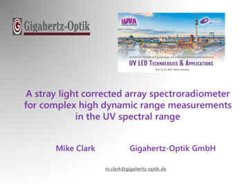
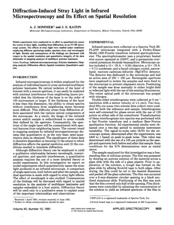
optimum results for a given line-width require fine-tuning, which renders complications anduncertainties when the spectrum contains lines with variations in bandwidths.In this article, we present a general method – Periodic Shadowing (PS) – for stray lightelimination that is suitable for all spectrographs with stigmatic imaging properties, thusincluding nearly all modern instruments optimized for use of 2D detectors (or 1D sensorarrays).2. Periodic shadowingPeriodic Shadowing, which is mainly inspired by lock-in amplification [25] (frequencymodulation and phase-sensitive detection in the temporal domain) and Structured IlluminationMicroscopy [26] (employed in microscopic imaging to increase depth-resolution), stronglyreduce the stray light problem by tagging the photons incident on the spectrograph with acertain, predefined pattern. The configuration being presented here utilizes a Ronchi (squarewave) grid target, mounted at the entrance slit (Fig. 1(a)), to tag the light – no othermodification to the hardware of the spectroscopic system is required.Fig. 1. Schematic view of the experimental arrangement. (a) The inserted Ronchi pattern at theentrance slit is the only hardware modification to the spectrograph. (b) Unprocessed PSspectrum of an argon discharge lamp in which the superimposed periodic shadows can beobserved.Owing to the fact that the entrance slit is imaged onto the detector at all wavelengths, thefine stripes of the Ronchi grid will effectively cast periodic shadows with a given spatialfrequency and phase (along the slit direction), superimposed on all spectral lines (Fig. 1(b)).The stray light is, by definition, incapable of maintaining this well-defined structure during itspassage through the spectrograph and will, in contrast to the signal photons, appear as awavelength-dependent intensity offset on the detector. This distinction allows the signalphotons to be identified and separated from the stray light, both in one and two-dimensionalmeasurements, using a simple post-processing routine. We incorporate a lock-in detectionalgorithm [26] on each column of the acquired spectrum to extract only the information thatappears with exactly the same periodicity as that of the Ronchi grid (procedure outlined inAppendix A). Apart from suppressing stray light, this approach also has the added benefit ofreducing the impact of white noise. Furthermore, with the tagging process and dataacquisition occurring simultaneously, pre-calibrations and blank- or background recordingsare avoided.3. Results and discussionTo experimentally verify the capabilities and versatility of the PS technique, fourspectroscopic methods were studied, selected to achieve a high experimental diversity; (1)emission – where intense lines are known to gives rise to locally elevated levels of stray light;#205453 - 15.00 USD(C) 2014 OSAReceived 24 Jan 2014; revised 17 Feb 2014; accepted 17 Feb 2014; published 26 Mar 20147 April 2014 Vol. 22, No. 7 DOI:10.1364/OE.22.007711 OPTICS EXPRESS 7713
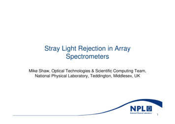
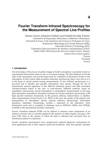
(2) absorption – where the added intensity from stray light lead to an underestimatedabsorption; (3) laser-induced scattering – where stray light from the intense laser lineconceals spectral features; and (4) Coherent anti-Stokes Raman Spectroscopy – todemonstrate that PS can be applied in spectral analysis of coherent signals. Each set ofexperiment was compared with the corresponding conventional method.3.1 EmissionTo study natural emission the radiation from a cadmium discharge lamp was recorded, seeFig. 2. The benefits of this sample are that its emission is not particularly intense and thevisible spectrum contains well-separated lines. Stray light contamination is thus expected tobe moderate. Despite this, a large improvement in line contrasts is observed when comparingthe PS and conventional spectrum (Fig. 2(a)). Figure 2(b) shows how the stray lightcontribution varies significantly across the spectrum, increasing by a factor of up to 300 inline-rich regions. As explained by Larson et. al [11], this local increase of stray light is due toa superposition of wings from strong emission lines and is particularly problematic tocompensate for as the magnitude of the effect depends on the current – often unknown – stateof the sample. However, if left unaccounted for these enhancements directly transfer intoanalytical errors, as is exemplified by the signal-to-background values (Figs. 2(c)–2(e)).Fig. 2. Spectrum from a cadmium discharge lamp, acquired using both PS and conventionalspectroscopy. (a) With its ability to distinguish between stray light and signal photons on apixel level, PS generates a spectrum with line contrasts that greatly exceed the conventionalones (note the logarithmic scale). Both spectra are scaled between zero and unity. (b) Ratiobetween conventional and PS spectrum, revealing the complex structure of the stray lightintensity, increasing nearby line-rich regions. This behavior demonstrates how the stray lightlevel cannot be assessed indirectly by evaluating the baseline in vacant regions of thespectrum. (c)-(e) Weak spectral lines residing on the wings of strong emission lines areproblematic to monitor accurately due to the locally elevated levels of stray light. PSsignificantly improves the signal-to-background values for such weak lines (indicated by thearrows).3.2 AbsorptionAstronomical observations rely almost entirely on passive methods, absorption and emissionspectroscopy being among the most important ones [2] but where the former is particularlysensitive to stray light contamination. In a spectroscopic stellar measurement stray light#205453 - 15.00 USD(C) 2014 OSAReceived 24 Jan 2014; revised 17 Feb 2014; accepted 17 Feb 2014; published 26 Mar 20147 April 2014 Vol. 22, No. 7 DOI:10.1364/OE.22.007711 OPTICS EXPRESS 7714
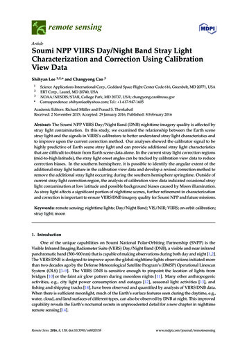
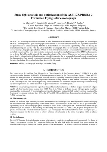
lowers the continuum level (broadband blackbody radiation) while filling the absorption lines,thus smoothening spectral features, in turn generating systematic errors in spectral- linewidths, depths and shapes. A double or triple monochromator arrangement yields lower straylight levels, but these systems are generally avoided in astronomy nowadays (for thepreviously mentioned reasons) in favor of CCD-based systems. The ability to suppress straylight on a 2D arrangement thus makes PS promising for the prospect of increased sensitivity,which is key when weak spectral signatures are sought, e.g. when attempting to study theatmosphere of extrasolar planets [4,5]. Here a faint absorption imprint – only a fraction of thecontinuum level – is superposed on an overwhelmingly bright stellar spectrum and evenminute spectral distortions due to stray light contamination are thus crucial to avoid. Figure 3shows a high-resolution absorption spectrum of the sun where the benefits of the PStechnique for absorption applications in general are demonstrated (note that, apart fromsubtracting the average intensity on either side of the stellar exposure in the conventionalcase, no other corrections were carried out in this measurement).Fig. 3. Solar absorption spectrum, acquired using either conventional spectroscopy or PS. (a)Conventional spectrum of the sun. The significant amount of stray light is believed to arisefrom ruling deficiencies. (b) The corresponding PS spectrum, characterized by sharper,stronger absorption lines. The inset highlights the considerable difference in intensity for theprominent Fraunhofer lines of sodium at 5890 Å (D2) and 5896 Å (D1).3.3 ScatteringOne of the most frequently employed laser-induced methods within spectroscopy is Ramanscattering – an inelastic process where the generated frequency shift permits species-specificmeasurements [8]. However, laser-induced Raman scattering measurements are often largelyaffected by stray light arising from the intense elastic scattering (Rayleigh, Mie and Tyndallscattering, as well as reflections) – often manifested as a broad, expanding wing. Because ofthis and the relatively low scattering Raman cross-section, stray light interference has been along-standing complication for Raman spectroscopy and transitions at low wavenumbers arerarely included in the analysis [15,17,22,23,27]. Figure 4 illustrates how the transitions nearthe laser wavelength become readily accessible by means of PS, thus opening up for newmeasurement routines and identification procedures. Experimental and theoretical spectrashow excellent agreement (Figs. 4(c) and 4(d)), confirming a proper operation of the PSmethod. However, since PS is primarily a post-processing tool, sharp notch filters may still berequired in laser-based applications to diminish the strong laser radiation and to improve thesignal-to-noise ratio (S/N).#205453 - 15.00 USD(C) 2014 OSAReceived 24 Jan 2014; revised 17 Feb 2014; accepted 17 Feb 2014; published 26 Mar 20147 April 2014 Vol. 22, No. 7 DOI:10.1364/OE.22.007711 OPTICS EXPRESS 7715
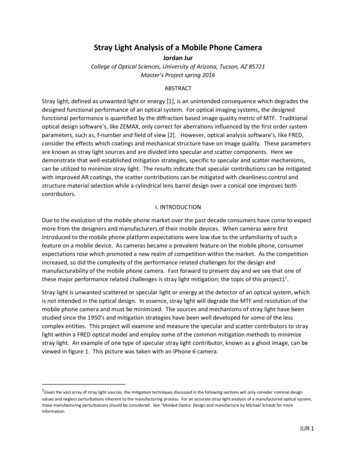
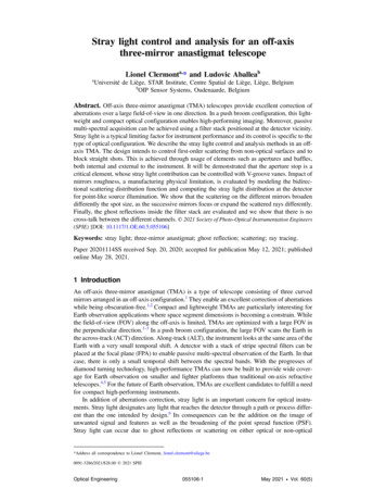
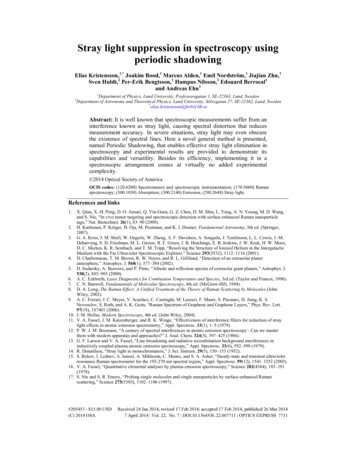
Fig. 4. Comparison between PS and conventional laser-induced rotational Raman spectroscopyin a gaseous medium. (a) and (b) Raman spectra of pure nitrogen and oxygen, respectively.Since Raman scattering is considerably weaker than Rayleigh scattering, stray lightsuppression becomes a necessity for the detection of Raman transitions at low wavenumbers.Mie and Tyndall scattering as well as reflections are also contributing to the elastic light inmost practical measurement situations. The PS data illustrates the prospect of increasing theoperating range of Raman spectroscopy, to permit accurate monitoring of lines closer to thelaser line. (c) and (d) Theoretical Raman spectra fitted against PS spectra, showing excellentagreement.3.4 Coherent signalsSimilar to Raman scattering, coherent anti-stokes Raman spectroscopy (CARS) is also alaser-based technique that provides species-specificity, used for both micro- and macroscopicapplications [6,28–30]. However, the signal generated in CARS is, in contrast to Ramanscattering, coherent and has laser-like characteristics, thus permitting additional schemes forstray light suppression based on polarization, long optical paths and sharp, optical filters.Further, in situations when the acquired data still suffer from errors induced by stray light, thelaser configuration of CARS (wave-mixing of laser beams with different wavelengths) allowsthe background offset to be measured in a separate recording. A PS spectrum, acquired atsuch measurement conditions using a two-beam rotational CARS configuration [31], isdisplayed in Fig. 5(a) accompanied by raw data as well as background-corrected CARS data.The residual signal, in Fig. 5(b), shows an excellent agreement between the two differentlyprocessed data sets, demonstrating both that background acquisitions in CARS – whenrequired – can be circumvented by means of PS (Figs. 5(a) and 5(c)) and that PS is applicablefor the analysis of coherent signals. Apart from being more time efficient, the greatest meritof PS for CARS experiments is arguably the possibility of recording single laser shot spectra,even in harsh environments where e.g. beam-steering and changes in polarization gives rise totemporal fluctuations in the stray light contribution (Fig. 5(d)).#205453 - 15.00 USD(C) 2014 OSAReceived 24 Jan 2014; revised 17 Feb 2014; accepted 17 Feb 2014; published 26 Mar 20147 April 2014 Vol. 22, No. 7 DOI:10.1364/OE.22.007711 OPTICS EXPRESS 7716
Fig. 5. Comparison of rotational CARS spectra acquired using either PS or conventionalspectroscopy. (a) CARS evaluation is commonly made on a signal spectrum from which abackground spectrum (recorded while blocking the Stokes beam) is subtracted. Byimplementing PS, the requisite for such a second measurement is circumvented. (b) Residualplot, showing the close agreement between background-corrected CARS and PS,experimentally verifying a proper operation of PS for coherent signals. (c) Example of aspectrum from a two-beam CARS measurement, where the polarization of the spatiallyoverlapping probe beam is perturbed as it passes through an optical window, in an attempt tomimic undesired effects commonly encountered in e.g. high-pressure measurements, whereoptical ports are a necessity. (d) Example of an instantaneously acquired CO2 spectrum,recorded under similar conditions. Due to temporal fluctuations of the conditions in themeasurement volume, accurate background readings cannot be attained without PS.3.5 Signal to noiseLosing light is an inevitable side effect of all modulation schemes. In the case of PS theinserted Ronchi grid blocks about half of the incident light, thus potentially reducing the S/Nby an equal amount. However, the a priori characteristics of the signal of interest – its uniquespatial phase and frequency – can be exploited to reduce noise. Two processes are mainlyresponsible for the filtering of noise. First, the signal is shifted to a less noisy environment(high spatial frequency), thus reducing the influence of white noise. Second, a (spatial) bandpass filter is applied on the signal, removing redundant spatial frequencies that otherwise addnoise. This noise-filtering capability is illustrated in Fig. 6, showing statistical analysis on aCARS measurement of air. Analysis of regions free from spectral lines revealed a reductionof the noise by at least a factor of two when implementing PS (Fig. 6), thus fullycompensating, in terms of S/N, for the loss of light introduced by the Ronchi grid.#205453 - 15.00 USD(C) 2014 OSAReceived 24 Jan 2014; revised 17 Feb 2014; accepted 17 Feb 2014; published 26 Mar 20147 April 2014 Vol. 22, No. 7 DOI:10.1364/OE.22.007711 OPTICS EXPRESS 7717
Fig. 6. Comparison of the noise levels for rotational CARS spectra of air. (a) UnprocessedCARS spectrum. (b) Background-corrected CARS spectrum. (c) Corresponding PS spectrum.The green frame indicates the region of interest (ROI) for the analysis, chosen for being free ofspectral lines. Each spectrum is normalized prior to the statistical analysis, having valuesbetween zero and unity. The S/N can therefore be estimated directly from the noise level(being inversely proportional to the standard deviation). (d)-(f) Histograms of the ROI afterfull vertical binning (FVB), revealing a reduction of the noise by approximately a factor of 2with PS. (g)-(i) Histograms of the ROI with no pixel binning, suggesting an even greaterimprovement in S/N.4. ConclusionIn conclusion, a novel spectroscopic method, having the capability of suppressing stray light,has been described and experimentally demonstrated. The basic principle of the methodconsists of applying a pattern that blocks light with a certain periodicity against the entranceslit of the spectrometer. This predefined transmission characteristic is only maintained byphotons traveling the correct optical path through the spectrometer, thus making stray lightand signal photons distinguishable in the acquired spectrum. To extract the signal photons andsuppress the unwanted stray light, we incorporate a spatial lock-in algorithm, which also hasnoise-filtering benefits.Besides its ability to suppress stray light, Periodic Shadowing is inexpensive and addsnearly no experimental complexity to the spectroscopic setup.#205453 - 15.00 USD(C) 2014 OSAReceived 24 Jan 2014; revised 17 Feb 2014; accepted 17 Feb 2014; published 26 Mar 20147 April 2014 Vol. 22, No. 7 DOI:10.1364/OE.22.007711 OPTICS EXPRESS 7718
Appendix A: Lock-in AnalysisFig. 7. Example of the processing steps of PS. Each graph is accompanied by its correspondingFourier transforms, all shown in a logarithmic scale (x-axis truncated). (a) Unprocessedrotational CARS spectrum. (b) Corresponding PS spectrum. (c) Intensity variations along thecolumns “A” (blue). (d) Intensity variations along the columns “B” (red). (e) Referencessignals, 90 degrees shifted in phase. (f) Product of the first reference signal and both “A” and“B”. (g) Product of second reference signal and both “A” and “B”. (h) Result of the PSalgorithm, which extracts the envelope (AA) of column “A”. The low-pass filter (LPF) is shownin a linear scale. (i) Difference in noise level (column B) between PS (black) and conventionalspectroscopy (red), where the latter is offset-adjusted, for reasons of clarity.The lock-in analysis outlined in this appendix is graphically represented in Fig. 7. To be ableto use lock-in detection algorithms in the data post-processing of PS the signal must bemodulated with a well-defined spatial frequency. In PS, this frequency, fSig, is set by themagnification (or demagnification) of the Ronchi ruling, which typically has 5-20periods/mm. Although remaining constant, we routinely determine fSig from each data setthrough Fourier analysis, where the software simply assumes fSig to be the strongest non-zerocomponent in the Fourier domain (for optimum performance it is advised to exclude lowspatial frequencies in the analysis to avoid ambiguities caused by the 1/f noise). With fSig#205453 - 15.00 USD(C) 2014 OSAReceived 24 Jan 2014; revised 17 Feb 2014; accepted 17 Feb 2014; published 26 Mar 20147 April 2014 Vol. 22, No. 7 DOI:10.1364/OE.22.007711 OPTICS EXPRESS 7719
being determined, each column, SC, of the 2D spectrum (Fig. 7(a)) is then analyzedseparately. This signal vector can be expressed asSC ( R ) AC ( R ) sin(2π f Sig R ϕC ) BC ( R )(1)The row index, R, and column index, C, are integer numbers. In this formulation the signal isdivided into two parts; (1) the frequency modulated part, AC(R), which basically contains thesignal of interest (SOI), and (2) a non-modulated offset, BC(R), arising from various sourcesof noise and interference. If we assume that fSig remains constant for all columns – areasonable assumption in PS – two reference signals, SX,Ref and SY,Ref (see Fig. 7(e)) can beformed asS X , Ref ( R ) sin ( 2π f Sig R ϕ Ref)(2)andSY , Ref ( R ) sin ( 2π f Sig R ϕ Ref π 2 )(3)where the phase shift of π/2 is the only difference between the two. Multiplying the signalvector, SC, with the two reference signals leads the following signal vectors (see Figs. 7(f) and7(g)).S X ,C ( R ) SC ( R ) S X , Ref BC ( R ) sin ( 2π f Sig R ϕ Ref )SY ,C ( R ) SC ( R ) SY , Ref BC ( R ) sin ( 2π f Sig R ϕ Ref1AC ( R ) [cos (ϕ C ϕ Ref ) cos ( 4π f Sig R ϕC ϕ Ref )] 2(4)1AC ( R ) sin (ϕ C ϕ Ref ) sin ( 4π f Sig R ϕ C ϕ Ref ) 2(5) π 2)Applying a low-pass filter with a cut-off frequency of fC fSig (lower right panel in Fig. 7(h))on these vectors (ideally) removes the modulated components, resulting in two new vectors,XC (R) 1 AC ( R ) cos (ϕC ϕ Ref2)(6)YC ( R ) 1 AC ( R ) sin (ϕC ϕ Ref2)(7)andwhere the tilde assignment on AC is due to the frequency filtering. In the presented results, weapply a pure Gaussian to reject higher spatial frequencies. The SOI is finally determined bycalculating22A C ( R ) 2 X C ( R ) YC ( R )(8)which basically extracts the envelope of SC (Fig. 7(h)).Analyzing the data using lock-in algorithms leads to a slight loss of spatial resolution, themagnitude of which is inversely proportional to the spatial frequency of the Ronchi grating.Selecting a Ronchi grating with high spatial frequency is therefore advised to minimize theloss of spatial resolution. However, 2D PS spectroscopy with no loss of spatial resolution canbe achieved by shifting the Ronchi grating physically in space, following the methodologydescribed by Neil et al. [26]. By shifting the grating and thereby the spatial phase of theshadow structure, the information previously hidden in the shadows becomes accessible.#205453 - 15.00 USD(C) 2014 OSAReceived 24 Jan 2014; revised 17 Feb 2014; accepted 17 Feb 2014; published 26 Mar 20147 April 2014 Vol. 22, No. 7 DOI:10.1364/OE.22.007711 OPTICS EXPRESS 7720
Recording three spectra with relative spatial phases 0, 2π/3 and 4π/3 is sufficient for a fulldemodulation, according toPS ( I 0 I 2π / 3 )2 ( I 0 I 4π / 3 ) ( I 2π / 3 I 4π / 3 )22(9)where IX is a 2D spectrum and the subscript X denote the spatial phase (in radians) of theshadows.AcknowledgmentsThis work was supported by the Linné Center within the Lund Laser Center (LLC) as well asthe Center for Combustion Science and Technology (CECOST) through the Swedish EnergyAgency. Also the European Research Council (ERC) Advanced Grant DALDECS isacknowledged.The authors gratefully acknowledge Dainis Dravins, Nils Ryde, JeromeWorkman and Sune Svanberg for helpful discussions.#205453 - 15.00 USD(C) 2014 OSAReceived 24 Jan 2014; revised 17 Feb 2014; accepted 17 Feb 2014; published 26 Mar 20147
Stray light suppression in spectroscopy using periodic shadowing Elias Kristensson,1,* Joakim Bood, 1 Marcus Alden, Emil Nordström, Jiajian Zhu,1 Sven Huldt, 2 Per-Erik Bengtsson, 1 Hampus Nilsson, Edouard Berrocal and Andreas Ehn1 1Department of Physics, Lund University, Professorsgatan 1, SE-22363