Transcription
book.book Page 1 Wednesday, April 25, 2012 12:34 PMDell XPS 8300 ServiceManualModel: D03M SeriesType: D03M001
book.book Page 2 Wednesday, April 25, 2012 12:34 PMNotes, Cautions, and WarningsNOTE: A NOTE indicates important information that helps you make better use ofyour computer.CAUTION: A CAUTION indicates either potential damage to hardware or loss ofdata and tells you how to avoid the problem.WARNING: A WARNING indicates a potential for property damage, personalinjury, or death.Information in this document is subject to change without notice. 2010 Dell Inc. All rights reserved.Trademarks used in this text: Dell , the DELL logo, and XPS are trademarks of Dell Inc.;Microsoft , Windows , and the Windows start button logoare either trademarks or registeredtrademarks of Microsoft Corporation in the United States and/or other countries; Bluetooth is aregistered trademark owned by Bluetooth SIG, Inc. and is used by Dell under license.Reproduction of these materials in any manner whatsoever without the written permission of Dell Inc.is strictly forbidden.Regulatory model: D03M seriesDecember 2010Regulatory Type: D03M004Rev. A00
book.book Page 3 Wednesday, April 25, 2012 12:34 PMContents1Technical Overview . . . . . . . . . . . . . . . . .Inside View of Your ComputerBefore You Begin10. . . . . . . . . . . . . . . . . .13Technical SpecificationsRecommended Tools. . . . . . . . . . . . . . . .13. . . . . . . . . . . . . . . . . .13. . . . . . . . . . . . . . .13Safety Instructions. . . . . . . . . . . . . . . . . . .14Computer Cover. . . . . . . . . . . . . . . . . . .17Turning Off Your Computer349. . . . . . . . . . . . . . .System Board Components2. . . . . . . . . . . . . .9Removing the Computer Cover. . . . . . . . . . . . .17Replacing the Computer Cover. . . . . . . . . . . . .18. . . . . . . . . . . . . . . . .21Memory Module(s)Removing the Memory Module(s) . . . . . . . . . . .21Replacing the Memory Module(s). . . . . . . . . . .22Contents3
book.book Page 4 Wednesday, April 25, 2012 12:34 PM5678Front Bezel. . . . . . . . . . . . . . . . . . . . . . .27Removing the Front Bezel. . . . . . . . . . . . . . . .27Replacing the Front Bezel. . . . . . . . . . . . . . . .29Graphics Card Bracket. . . . . . . . . . . . . .31Removing the Graphics Card Bracket . . . . . . . . .31Replacing the Graphics Card Bracket. . . . . . . . .32. . . . . . . . . . . . . . . . .33Wireless Mini-CardRemoving the Mini-Card . . . . . . . . . . . . . . . .33Replacing the Mini-Card. . . . . . . . . . . . . . . .34. . . . . . . . . . . . . . . . . .37PCI Express CardsRemoving the Card Retention Bracket. . . . . . . . .37Replacing the Card Retention Bracket. . . . . . . . .38Removing PCI Express Cards. . . . . . . . . . . . . .39Replacing PCI Express Cards. . . . . . . . . . . . . .41Configuring Your Computer After Removing or Installing the PCIExpress Card . . . . . . . . . . . . . . . . . . . . . . . 429Drives. . . . . . . . . . . . . . . . . . . . . . . . . . .Hard Drive. . . . . . . . . . . . . . . . . . . . . . . .Removing the Primary Hard Drive4Contents. . . . . . . . .454545
book.book Page 5 Wednesday, April 25, 2012 12:34 PMRemoving the Hard Drive Cage. . . . . . . . . .46Removing the Secondary Hard Drive. . . . . . .47Replacing the Secondary Hard Drive. . . . . . .48. . . . . . . . . .49Replacing the Hard Drive CageReplacing the Primary Hard DriveOptical Drive. . . . . . . . .49. . . . . . . . . . . . . . . . . . . . . .50Removing the Optical Drive. . . . . . . . . . . .50Replacing the Optical Drive. . . . . . . . . . . .51. . . . . . . . . . . . . . . . . . .54Media Card ReaderRemoving the Media Card Reader. . . . . . . . .54Replacing the Media Card Reader. . . . . . . . .56. . . . . . . . . . . . . . . . . . . . . . . .5710 Top CoverRemoving the Top Cover . . . . . . . . . . . . . . . .57Replacing the Top Cover. . . . . . . . . . . . . . . .59. . . . . . . . . . . . . . . . . . . . .6111 Top I/O Panel .Removing the Top I/O Panel . . . . . . . . . . . . . .61Replacing the Top I/O Panel. . . . . . . . . . . . . .63. . . . . . . . . . . . . . . . . . .6512 Front USB PanelRemoving the Front USB Panel. . . . . . . . . . . . .65Replacing the Front USB Panel. . . . . . . . . . . . .67Contents5
book.book Page 6 Wednesday, April 25, 2012 12:34 PM13 Bluetooth Assembly. . . . . . . . . . . . . . . .69Removing the Bluetooth Assembly. . . . . . . . . . .69Replacing the Bluetooth Assembly. . . . . . . . . . .71. . . . . . . . . . . . . . .7314 Power Button ModuleRemoving the Power Button Module. . . . . . . . . .73Replacing the Power Button Module. . . . . . . . . .75. . . . . . . . . . . . . . . . . . . . . . . . . . . . .7715 FansChassis Fan. . . . . . . . . . . . . . . . . . . . . . .77Removing the Chassis Fan. . . . . . . . . . . . .77Replacing the Chassis Fan. . . . . . . . . . . . .78Processor Fan and Heat-Sink Assembly. . . . . . . .79Removing the Processor Fan and Heat-Sink Assembly 79Replacing the Processor Fan and Heat-Sink Assembly 8116 Processor. . . . . . . . . . . . . . . . . . . . . . . .Removing the Processor . . . . . . . . . . . . . . . .83Replacing the Processor. . . . . . . . . . . . . . . .85. . . . . . . . . . . . . . . . . . .8917 Coin-Cell Battery6Contents83Removing the Coin-Cell Battery. . . . . . . . . . . . .89Replacing the Coin-Cell Battery. . . . . . . . . . . .90
book.book Page 7 Wednesday, April 25, 2012 12:34 PM18 Power Supply93. . . . . . . . . . . . . . . . . . . . .Removing the Power Supply. . . . . . . . . . . . . .93Replacing the Power Supply. . . . . . . . . . . . . .95. . . . . . . . . . . . . . . . . . . . .9719 System BoardRemoving the System Board. . . . . . . . . . . . . .97Replacing the System Board. . . . . . . . . . . . . .99Entering the Service Tag in the BIOS20 System Setup UtilityOverview101. . . . . . . . . . . . . . . . . . . . . . . .103103. . . . . . . . . . . . . . . . . . . . . . . . . . . . . . . . . .103. . . . . . . . . . . . . . .104. . . . . . . . . . . . . . . . . .109Entering System Setup UtilitySystem Setup OptionsBoot Sequence . . . . . . . . . . . . .110. . . . . . . . . . . . . . .112Clearing Forgotten PasswordsClearing CMOS Passwords21 Flashing the BIOS. . . . . . . . . . . . . . . . .115Contents7
book.book Page 8 Wednesday, April 25, 2012 12:34 PM8Contents
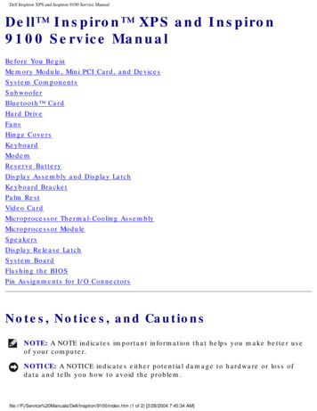
book.book Page 9 Wednesday, April 25, 2012 12:34 PM3Technical OverviewWARNING: Before working inside your computer, read the safety informationthat shipped with your computer. For additional safety best practices information,see the Regulatory Compliance Homepage atwww.dell.com/regulatory compliance.WARNING: To avoid electrostatic discharge, ground yourself by using a wristgrounding strap or by periodically touching an unpainted metal surface (such as aconnector on your computer).CAUTION: Only a certified service technician should perform repairs on yourcomputer. Damage due to servicing that is not authorized by Dell is not covered byyour warranty.Inside View of Your Computer128973456Technical Overview9
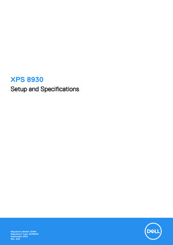
book.book Page 10 Wednesday, April 25, 2012 12:34 PM1front bezel2primary hard drive3graphics card bracket (optional)4secondary hard drive5system board6card retention clamp7power supply8primary optical drive9secondary optical driveSystem Board Components2134 5 6 7278262592410231122122110Technical Overview201918 1716 15 1413
book.book Page 11 Wednesday, April 25, 2012 12:34 PM1power connector (PWR2)2processor socket3processor fan connector(CPU FAN)4memory module connector(DIMM3)5memory module connector(DIMM1)6memory module connector(DIMM4)7memory module connector(DIMM2)8main power connector(PWR1)9password reset jumper (PSWD)10CMOS reset jumper (RTCRST)11SATA drive connector (SATA 0)12power button connector(F PANEL)13SATA drive connector (SATA 1)14front panel USB connector(F USB1)15SATA drive connector (SATA 2)16front panel USB connector(F USB3)17SATA drive connector (SATA 3)18battery socket (BATTERY)19front panel USB connector(F USB2)20front panel USB connector(F USB4)21front panel audio connector(F AUDIO1)22PCI Express x1 card slot(PCI-EX1 3)23PCI Express x1 card slot(PCI-EX1 2)24PCI Express x1 card slot(PCI-EX1 1)25PCI Express x16 card slot(PCI-EX16 1)26Mini-Card slot(PCIE MINICARD)27chassis fan connector(SYS FAN 1)Technical Overview11
book.book Page 12 Wednesday, April 25, 2012 12:34 PM12Technical Overview
book.book Page 13 Wednesday, April 25, 2012 12:34 PM1Before You BeginThis manual provides instructions for removing and installing thecomponents in your computer. Unless otherwise noted, each procedureassumes that the following conditions exist: You have performed the steps in "Turning Off Your Computer" on page 13and "Safety Instructions" on page 14. You have read the safety information that shipped with your computer. A component can be replaced or—if purchased separately—installed byperforming the removal procedure in reverse order.Technical SpecificationsFor information on technical specifications of your computer, see the SetupGuide at support.dell.com/manuals.Recommended ToolsThe instructions in this document may require the following tools: Small flat-blade screwdriver Small Phillips screwdriver Plastic scribe BIOS executable update program available at support.dell.comTurning Off Your ComputerCAUTION: To avoid losing data, save and close all open files and exit all openprograms before you turn off your computer.1 Save and close all open files and exit all open programs.2 To shut down the operating system, click StartDown.and then click ShutBefore You Begin13
book.book Page 14 Wednesday, April 25, 2012 12:34 PM3 Ensure that the computer is turned off. If your computer did notautomatically turn off when you shut down the operating system, pressand hold the power button until the computer turns off.Safety InstructionsUse the following safety guidelines to help protect your computer frompotential damage and to help ensure your own personal safety.WARNING: Before working inside your computer, read the safety informationthat shipped with your computer. For additional safety best practices information,see the Regulatory Compliance Homepage atwww.dell.com/regulatory compliance.CAUTION: Only a certified service technician should perform repairs on yourcomputer. Damage due to servicing that is not authorized by Dell is not covered byyour warranty.CAUTION: When you disconnect a cable, pull on its connector or on its pull-tab,not on the cable itself. Some cables have connectors with locking tabs; if you aredisconnecting this type of cable, press in on the locking tabs before youdisconnect the cable. As you pull connectors apart, keep them evenly aligned toavoid bending any connector pins. Also, before you connect a cable, ensure thatboth connectors are correctly oriented and aligned.CAUTION: To avoid damaging the computer, perform the following steps beforeyou begin working inside the computer.1 Ensure that the work surface is flat and clean to prevent the computercover from being scratched.2 Turn off your computer (see "Turning Off Your Computer" on page 13)and all attached devices.CAUTION: To disconnect a network cable, first unplug the cable from yourcomputer and then unplug the cable from the network device.3 Disconnect all telephone or network cables from the computer.4 Disconnect your computer and all attached devices from their electricaloutlets.5 Disconnect all attached devices from your computer.6 Press and eject any installed cards from the Media Card Reader.7 Press and hold the power button to ground the system board.14Before You Begin
book.book Page 15 Wednesday, April 25, 2012 12:34 PMCAUTION: Before touching anything inside your computer, ground yourself bytouching an unpainted metal surface, such as the metal at the back of thecomputer. While you work, periodically touch an unpainted metal surface todissipate static electricity, which could harm internal components.Before You Begin15
book.book Page 16 Wednesday, April 25, 2012 12:34 PM16Before You Begin
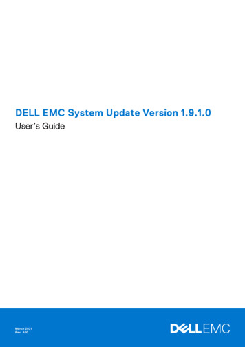
book.book Page 17 Wednesday, April 25, 2012 12:34 PM2Computer CoverWARNING: Before working inside your computer, read the safety information thatshipped with your computer. For additional safety best practices information, seethe Regulatory Compliance Homepage at www.dell.com/regulatory compliance.WARNING: To guard against likelihood of electric shock, laceration by movingfan blades, or other unexpected injuries, always unplug your computer from theelectrical outlet before removing the cover.WARNING: Do not operate your computer with any cover(s) (including computercovers, bezels, filler brackets, front-panel inserts, etc.) removed.CAUTION: Only a certified service technician should perform repairs on yourcomputer. Damage due to servicing that is not authorized by Dell is not covered byyour warranty.CAUTION: Ensure that sufficient space exists to support the computer with thecover removed—at least 30 cm (1 ft.) of desk top space.Removing the Computer Cover1 Follow the instructions in "Before You Begin" on page 13.2 Lay the computer on its side with the computer cover facing up.3 Remove the thumbscrew that secures the computer cover to the chassis,using a screw driver, if necessary.4 Release the computer cover by sliding it away from the front of thecomputer.5 Lift the cover away from the computer and set it aside in a secure location.Computer Cover17
book.book Page 18 Wednesday, April 25, 2012 12:34 PM121thumbscrew2computer coverReplacing the Computer Cover1 Follow the instructions in "Before You Begin" on page 13.2 Connect all the cables and fold the cables out of the way.3 Ensure that no tools or extra parts are left inside the computer.4 Align the tabs at the bottom of the computer cover with the slots locatedalong the edge of the chassis.5 Press the computer cover down and slide it towards the front of the computer.6 Replace the thumbscrew that secures the computer cover to the chassis.18Computer Cover
book.book Page 19 Wednesday, April 25, 2012 12:34 PM2311thumbscrew3computer cover2slots7 Place the computer in an upright position.Computer Cover19
book.book Page 20 Wednesday, April 25, 2012 12:34 PM20Computer Cover
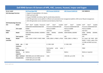
book.book Page 21 Wednesday, April 25, 2012 12:34 PM3Memory Module(s)WARNING: Before working inside your computer, read the safety informationthat shipped with your computer. For additional safety best practices information,see the Regulatory Compliance Homepage atwww.dell.com/regulatory compliance.WARNING: To guard against electrical shock, always unplug your computer fromthe electrical outlet before removing the cover.WARNING: Do not operate your computer with any cover(s) (including computercovers, bezels, filler brackets, front-panel inserts, etc.) removed.CAUTION: Only a certified service technician should perform repairs on yourcomputer. Damage due to servicing that is not authorized by Dell is not covered byyour warranty.Removing the Memory Module(s)1 Follow the instructions in "Before You Begin" on page 13.2 Remove the computer cover (see "Removing the Computer Cover" onpage 17).3 Locate the memory module(s) on the system board (see "System BoardComponents" on page 10).4 Press out the securing clip at each end of the memory module connector.Memory Module(s)21
book.book Page 22 Wednesday, April 25, 2012 12:34 PM211memory module connector2securing clip5 Grasp the memory module and pull it upwards.If the memory module is difficult to remove, gently ease the memorymodule back and forth to remove it from the connector.Replacing the Memory Module(s)1 Follow the instructions in "Before You Begin" on page 13.2 Press out the securing clip at each end of the memory module connector.CAUTION: Only a certified service technician should perform repairs on yourcomputer. Damage due to servicing that is not authorized by Dell is not covered byyour warranty.CAUTION: Do not install ECC or DDR3U memory modules.CAUTION: If you remove the original memory module(s) from your computerduring a memory upgrade, keep them separate from any new module(s) that youmay have, even if you purchased the new module(s) from Dell. If possible, do notpair an original memory module with a new memory module. Otherwise, yourcomputer may not start properly. The recommended memory configurations are:matched memory module(s) installed in DIMM connectors 1 and 2 and anothermatched memory module(s) installed in DIMM connectors 3 and 4.22Memory Module(s)
book.book Page 23 Wednesday, April 25, 2012 12:34 PM211matched memory modules inDIMM connectors 1 and 2 (whitesecuring clips)2matched memory modules inDIMM connectors 3 and 4 (blacksecuring clips)3 Align the notch on the bottom of the memory module with the tab in theconnector.Memory Module(s)23
book.book Page 24 Wednesday, April 25, 2012 12:34 PM42311cutouts (2)2tab3notch4memory moduleCAUTION: To avoid damage to the memory module, press the memory modulestraight down into the connector while you apply equal force to each end of thememory module.4 Insert the memory module into the connector until the memory modulesnaps into position.If you insert the memory module correctly, the securing clips snap into thecutouts at each end of the memory module.24Memory Module(s)
book.book Page 25 Wednesday, April 25, 2012 12:34 PM211cutouts (2)2securing clip (snapped inposition)5 Replace the computer cover (see "Replacing the Computer Cover" onpage 18).6 Connect your computer and devices to electrical outlets, and then turnthem on.If a message appears stating that the memory size has changed, press F1 to continue.7 Log on to your computer.To verify that the memory is installed correctly, click StartPanel System. ControlCheck the amount of memory (RAM) listed.Memory Module(s)25
book.book Page 26 Wednesday, April 25, 2012 12:34 PM26Memory Module(s)
book.book Page 27 Wednesday, April 25, 2012 12:34 PM4Front BezelWARNING: Before working inside your computer, read the safety informationthat shipped with your computer. For additional safety best practices information,see the Regulatory Compliance Homepage atwww.dell.com/regulatory compliance.WARNING: To guard against electrical shock, always unplug your computer fromthe electrical outlet before removing the cover.WARNING: Do not operate your computer with any cover(s) (including computercovers, front bezels, filler brackets, front-panel inserts, etc.) removed.CAUTION: Only a certified service technician should perform repairs on yourcomputer. Damage due to servicing that is not authorized by Dell is not covered byyour warranty.Removing the Front Bezel1 Follow the instructions in "Before You Begin" on page 13.2 Remove the computer cover (see "Removing the Computer Cover" onpage 17).3 Place the computer in an upright position.4 Grasp and release the front bezel tabs sequentially, one at a time by movingthem outward from the front panel.5 Rotate and pull the front bezel away from the front of the computer torelease the front bezel clamps from the front panel slots.Front Bezel27
book.book Page 28 Wednesday, April 25, 2012 12:34 PM123451front bezel2front panel slots (3)3front bezel tabs (4)4front bezel clamps (3)5front panel6 Set aside the front bezel in a secure location.28Front Bezel
book.book Page 29 Wednesday, April 25, 2012 12:34 PMReplacing the Front Bezel1 Follow the instructions in "Before You Begin" on page 13.2 Align and insert the front bezel clamps into the front panel slots.3 Rotate the front bezel towards the computer until the front bezel tabssnap into place.12345Front Bezel29
book.book Page 30 Wednesday, April 25, 2012 12:34 PM1front bezel2front bezel tabs (4)3front panel slots (3)4front bezel clamps (3)5front panel4 Replace the computer cover (see "Replacing the Computer Cover" onpage 18).30Front Bezel
book.book Page 31 Wednesday, April 25, 2012 12:34 PMGraphics Card Bracket5WARNING: Before working inside your computer, read the safety informationthat shipped with your computer. For additional safety best practices information,see the Regulatory Compliance Homepage atwww.dell.com/regulatory compliance.WARNING: To guard against electrical shock, always unplug your computer fromthe electrical outlet before removing the cover.WARNING: Do not operate your computer with any cover(s) (including computercovers, bezels, filler brackets, front-panel inserts, etc.) removed.CAUTION: Only a certified service technician should perform repairs on yourcomputer. Damage due to servicing that is not authorized by Dell is not covered byyour warranty.NOTE: The graphic card bracket is present in your computer only if you ordered adouble-width graphics card at the time of purchase.Removing the Graphics Card Bracket1 Follow the instructions in "Before You Begin" on page 13.2 Remove the computer cover (see "Removing the Computer Cover" onpage 17).3 Remove the two screws that secure the graphics card bracket to the chassis.4 Lift the graphics card bracket off the chassis.5 Set the graphics card bracket aside in a secure location.Graphics Card Bracket31
book.book Page 32 Wednesday, April 25, 2012 12:34 PM121screws (2)2graphics card bracketReplacing the Graphics Card Bracket1 Follow the instructions in "Before You Begin" on page 13.2 Align the screw holes on the graphics card bracket with the screw holes onchassis.3 Replace the two screws that secure the graphics card bracket to the chassis.4 Replace the computer cover (see "Replacing the Computer Cover" onpage 18).32Graphics Card Bracket
book.book Page 33 Wednesday, April 25, 2012 12:34 PM6Wireless Mini-CardWARNING: Before working inside your computer, read the safety informationthat shipped with your computer. For additional safety best practices information,see the Regulatory Compliance Homepage atwww.dell.com/regulatory compliance.WARNING: To guard against electrical shock, always unplug your computer fromthe electrical outlet before removing the cover.WARNING: Do not operate your computer with any cover(s) (including computercovers, bezels, filler brackets, front-panel inserts, etc.) removed.CAUTION: Only a certified service technician should perform repairs on yourcomputer. Damage due to servicing that is not authorized by Dell is not covered byyour warranty.CAUTION: To avoid electrostatic discharge, ground yourself by using a wristgrounding strap or by periodically touching an unpainted metal surface (such as aconnector on your computer).CAUTION: When the Mini-Card is not in the computer, store it in protectiveantistatic packaging (see "Protecting Against Electrostatic Discharge" in thesafety instructions that shipped with your computer).NOTE: Dell does not guarantee compatibility or provide support for Mini-Cardsfrom sources other than Dell.If you ordered a wireless Mini-Card with your computer, the card is alreadyinstalled.Your computer supports one half Mini-Card slot for Wireless Local AreaNetwork (WLAN).Removing the Mini-Card1 Follow the instructions in "Before You Begin" on page 13.Wireless Mini-Card33
book.book Page 34 Wednesday, April 25, 2012 12:34 PM2 Remove the computer cover (see "Removing the Computer Cover" onpage 17).3 Disconnect the antenna cable(s) from the Mini-Card.1231antenna cables (2)3clips (2)2Mini-Card4 Release the Mini-Card by pressing the clips on either side of the card.5 Lift the Mini-Card away from the system-board connector.CAUTION: When the Mini-Card is not in the computer, store it in protectiveantistatic packaging (see "Protecting Against Electrostatic Discharge" in thesafety instructions that shipped with your computer).Replacing the Mini-CardCAUTION: The connectors are keyed to ensure correct insertion. Use ofexcessive force may damage the connectors.CAUTION: To avoid damage to the Mini-Card, ensure that there are no cables orantenna cables under the Mini-Card.34Wireless Mini-Card
book.book Page 35 Wednesday, April 25, 2012 12:34 PM1 Follow the instructions in "Before You Begin" on page 13.2 Align the notch on the Mini-Card with the tab in the system-boardconnector.3 Insert the Mini-Card at a 45-degree angle into the system-boardconnector.4 Press the other end of the Mini-Card down until it clicks into place. If youdo not hear the click, remove the Mini-Card and reinstall it.5 Connect the appropriate antenna cables to the WLAN card you areinstalling. The WLAN card has two triangles marked on the label (blackand white): Connect the black cable to the connector marked with a blacktriangle. Connect the white cable to the connector marked with a whitetriangle.6 Replace the computer cover (see "Replacing the Computer Cover" onpage 18).7 Reconnect the computer and devices to electrical outlets, and then turnthem on.Wireless Mini-Card35
book.book Page 36 Wednesday, April 25, 2012 12:34 PM36Wireless Mini-Card
book.book Page 37 Wednesday, April 25, 2012 12:34 PM7PCI Express CardsWARNING: Before working inside your computer, read the safety informationthat shipped with your computer. For additional safety best practices information,see the Regulatory Compliance Homepage atwww.dell.com/regulatory compliance.WARNING: To guard against electrical shock, always unplug your computer fromthe electrical outlet before removing the cover.WARNING: Do not operate your computer with any cover(s) (including computercovers, bezels, filler brackets, front-panel inserts, etc.) removed.CAUTION: Only a certified service technician should perform repairs on yourcomputer. Damage due to servicing that is not authorized by Dell is not covered byyour warranty.Removing the Card Retention Bracket1 Follow the instructions in "Before You Begin" on page 13.2 Remove the computer cover (see "Removing the Computer Cover" onpage 17).3 Remove the screw that secures the card retention bracket.4 Lift the card retention bracket and set it aside in a secure location.PCI Express Cards37
book.book Page 38 Wednesday, April 25, 2012 12:34 PM121screw2card retention bracketReplacing the Card Retention Bracket1 Follow the instructions in "Before You Begin" on page 13.2 Replace the card retention bracket, ensuring that: The guide clamp is aligned with the guide notch. The top of all cards and filler brackets are flush with the alignment bar. The notch on top of the card or filler bracket fits around thealignment guide.3 Replace the screw that secures the card retention bracket.4 Replace the computer cover (see "Replacing the Computer Cover" onpage 18).38PCI Express Cards
book.book Page 39 Wednesday, April 25, 2012 12:34 PM12376451screw2guide clamps (2)3card retention bracket4alignment bar5alignment guide6filler bracket7guide notches (2)Removing PCI Express Cards1 Follow the instructions in "Before You Begin" on page 13.2 Remove the computer cover (see "Removing the Computer Cover" onpage 17).PCI Express Cards39
book.book Page 40 Wednesday, April 25, 2012 12:34 PM3 Remove the graphics card bracket, if applicable (see "Removing theGraphics Card Bracket" on page 31).4 Remove the card retention bracket (see "Removing the Card RetentionBracket" on page 37).5 Disconnect any cables connected to the card, if applicable.6 Remove the PCI Express card from the card slot: For a PCI Express x1 card, grasp the card by its top corners, and ease itout of its connector. For a PCI Express x16 card, push the securing tab, grasp the card by itstop corners, and then ease it out of its connector.51243401PCI Express x1 card2PCI Express x1 card slot3securing tab4PCI Express x16 card slot5PCI Express x16 cardPCI Express Cards
book.book Page 41 Wednesday, April 25, 2012 12:34 PM7 If you are removing the card permanently, install a filler bracket in theempty card-slot opening.NOTE: Installing filler brackets over empty card-slot openings is necessary tomaintain FCC certification of the computer. The brackets also keep dust anddirt out of your computer.Replacing PCI Express Cards1 Follow the instructions in "Before You Begin" on page 13.2 Prepare the card for installation.See the documentation that shipped with the card for information onconfiguring the card, making internal connections, or otherwisecustomizing it for your computer.3 Place the PCI Express card in the slot on the system board and press downfirmly. Ensure that the PCI Express card is fully seated in the slot.41321PCI Express x1 card2PCI Express x1 card slot3PCI Express x16 card slot4PCI Express x16 card4 Replace the card retention bracket (see "Replacing the Card RetentionBracket" on page 38).PCI Express Cards41
book.book Page 42 Wednesday, April 25, 2012 12:34 PM5 Connect any cables that should be attached to the card.See the documentation that shipped with the card for information aboutthe card’s cable connections.CAUTION: Do not route card cables over or behind the cards. Cables routed overthe cards can prevent the computer cover from closing properly or cause damageto the equipment.6 Replace the graphics card bracket, if applicable (see "Replacing theGraphics Card Bracket" on page 32).7 Replace the computer cover (see "Replacing the Computer Cover" onpage 18).8 Reconnect the computer and devices to electrical outlets, and then turnthem on.9 To complete the installation, see "Configuring Your Computer AfterRemoving or Installing the PCI Express Card" on page 42.Configuring Your Computer After Removing orInstalling the PCI Express CardNOTE: For information about the location of external connectors, see the SetupGuide. For information on installing drivers and software for your card, see thedocumentation that shipped with the card.42PCI Express Cards
book.book Page 43 Wednesday, April 25, 2012 12:34 PMInstalledRemovedSound card1 Enter system setup (see1 Enter system setup (seeNetwork card1 Enter system setup (see1 Enter system setup (see"System Setup Utility" onpage 103)2 Go to Onboard AudioController and then changethe setting to Disabled.3 Connect the external audiodevices to the sound card’sconnectors."System Setup Utility" onpage
2 Lay the computer on its side with the computer cover facing up. 3 Remove the thumbscrew that secures the computer cover to the chassis, using a screw driver, if necessary. 4 Release the computer cover by sliding it away from the front of the computer. 5 Lift the cover away from the