Transcription
SolidWorks Corporation: CSWP Sample ExamCertified SolidWorks Professional: Solid Modeling Specialist(CSWP-CORE)These questions are an example of what to expect in Segment 1 of the CSWP-CORE exam.How to take this sample exam:1. To best simulate the conditions of the real test, it is best NOT to print this exam. Sincethe Virtual Tester client window runs concurrently with SolidWorks you must switchback and forth between the two applications. Keeping this document open and consultingit on your computer while running SolidWorks is the best method to simulate the real testconditions.2. The multiple choice answers should serve as a check for you to ensure that your model ison the right track while completing this exam. If you do not find your answer in theselections offered then most likely there is something wrong with your model at thatpoint.3. Answers to the questions are on the last pages of this sample test document. There arealso hints that can help save time during the exam.4. If you can complete this exam and get at least 4 out of the 5 questions correctly in 30minutes or less then you should be ready to take the real CSWP exam.What you will need for the real CSWP exam:1. A computer that is running SolidWorks 2008 sp3.1 or higher.2. The computer must have a connection to the Internet.3. A double-monitor is recommended but not necessary.4. If you will be running the Virtual Tester client on a separate computer from the one thatis running SolidWorks, make sure there is a way to transfer files from one computer tothe other. You will be required to download SolidWorks files during the real test to beable to correctly answer some of the questions.
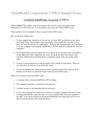
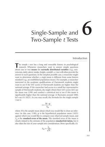
Sample Exam – Initial Part (These images are to be used to answer Questions #1 – 3)
1. Initial part – Stage 1: Build this part in SolidWorks.Unit system: MMGS (millimeter, gram, second)Decimal places: 2Part origin: ArbitraryMaterial: Alloy SteelDensity 0.0077 g/mm 3All holes through all unless shown otherwise-Use the following parameters and equations which correspond to the dimensions labeled in theimages:A 213 mmB 200 mmC 170 mmD 130 mmE 41 mmF Hole Wizard Standard: Ansi Metric CounterboreType: Hex Bolt – ANSI B18.2.3.5MSize: M8Fit: CloseThrough Hole Diameter: 15.00 mmCounterbore Diameter: 30.00 mmCounterbore Depth: 10.00 mmEnd Condition: Through AllX A/3Y B/3 10mmHint #1: The dimensions that are to be linked or updated and are variable will be labeled withletters. Any dimensions that are simple value changes from one stage to another will be circled inthe images.Hint #2: To save the most time, make use of linked dimensional values and equations.-Measure the mass of the part.What is the mass of the part (grams)?a)b)c)d)14139.6514298.5615118.4114207.34
2. Update parameters of the initial part.Unit system: MMGS (millimeter, gram, second)Decimal places: 2Part origin: ArbitraryMaterial: Alloy SteelDensity 0.0077 g/mm 3All holes through all unless shown otherwise-Use the following parameters and equations which correspond to the dimensions labeled in theimages:A 225 mmB 210 mmC 176 mmD 137 mmE 39 mmF Hole Wizard Standard: Ansi Metric CounterboreType: Hex Bolt – ANSI B18.2.3.5MSize: M8Fit: CloseThrough Hole Diameter: 15.00 mmCounterbore Diameter: 30.00 mmCounterbore Depth: 10.00 mmEnd Condition: Through AllX A/3Y B/3 10mmHint #1: The dimensions that are to be linked or updated and are variable will be labeled withletters. Any dimensions that are simple value changes from one stage to another will be circled inthe images.Hint #2: To save the most time, make use of linked dimensional values and equations.-Measure the mass of the part.What is the mass of the part (grams)?
3. Update parameters of the initial part.Unit system: MMGS (millimeter, gram, second)Decimal places: 2Part origin: ArbitraryMaterial: Alloy SteelDensity 0.0077 g/mm 3All holes through all unless shown otherwise-Use the following parameters and equations which correspond to the dimensions labeled in theimages:A 209 mmB 218 mmC 169 mmD 125 mmE 41 mmF Hole Wizard Standard: Ansi Metric CounterboreType: Hex Bolt – ANSI B18.2.3.5MSize: M8Fit: CloseThrough Hole Diameter: 15.00 mmCounterbore Diameter: 30.00 mmCounterbore Depth: 10.00 mmEnd Condition: Through AllX A/3Y B/3 10mmHint #1: The dimensions that are to be linked or updated and are variable will be labeled withletters. Any dimensions that are simple value changes from one stage to another will be circled inthe images.Hint #2: To save the most time, make use of linked dimensional values and equations.-Measure the mass of the part.What is the mass of the part (grams)?
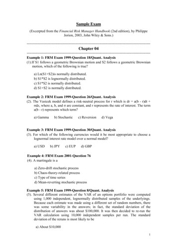
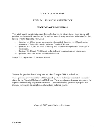
Stage 2: Modify the part using the following dimensions (These images are to be used toanswer Questions #4 and 5)Note: The changes from the initial part are concentrated in areas AA, BB and CC shown inthe first two images.
4. Stage 2Unit system: MMGS (millimeter, gram, second)Decimal places: 2Part origin: ArbitraryMaterial: Alloy SteelDensity 0.0077 g/mm 3All holes through all unless shown otherwise-Use the following parameters and equations which correspond to the dimensions labeled in theimages:A 221 mmB 211 mmC 165 mmD 121 mmE 37 mmX A/3Y B/3 15mmNote: The equation for Y has changed from the initial part.Hint #1: The dimensions that are to be linked or updated and are variable will be labeled withletters. Any dimensions that are simple value changes from one stage to another will be circled inthe images.Hint #2: To save the most time, make use of linked dimensional values and equations.-Measure the mass of the part.What is the mass of the part (grams)?a)b)c)d)13095.4013206.4013313.3513395.79
5. Stage 2 – Update ParametersUnit system: MMGS (millimeter, gram, second)Decimal places: 2Part origin: ArbitraryMaterial: Alloy SteelDensity 0.0077 g/mm 3All holes through all unless shown otherwise-Use the following parameters and equations which correspond to the dimensions labeled in theimages:A 229 mmB 217 mmC 163 mmD 119 mmE 34 mmX A/3Y B/3 15mmNote: The equation for Y has changed.Hint #1: The dimensions that are to be linked or updated and are variable will be labeled withletters. Any dimensions that are simple value changes from one stage to another will be circled inthe images.Hint #2: To save the most time, make use of linked dimensional values and equations.-Measure the mass of the part.What is the mass of the part (grams)?
Answers and Hints1.2.3.4.5.d) 14207.3416490.4515100.47b) 13206.4014208.00DISCLAIMER: IT IS UP TO YOU TO RESEARCH THESE HINTS. BEING APROFESSIONAL LEVEL CERTIFIED SOLIDWORKS USER SHOULD ALSO INCLUDETHE ABILITY TO RESEARCH SOLIDWORKS FUNCTIONALITY. CONSULT HELP,YOUR VAR AE’S, THE ON-LINE FORUMS OR BLOGS. NO ANSWERS WILL BESHARED BY THE CERTIFICATION TEAM!Hint #1: Use linked (also known as “shared values”) dimensions to manage the dimensions thatare to be the same in each stage. This will ensure that the dimensions that are to be linkedtogether in value stay linked together.Hint #2: Change the label of the dimensions in your part to A, B, C, D, etc. to visually keep trackof which dimensions need to be changed.Hint #3: As an alternative to Hint #2, you can also use the Design Table to manage the changingparameters.
SolidWorks Corporation: CSWP Sample Exam Certified SolidWorks Professional: Solid Modeling Specialist (CSWP-CORE) These questions are an example of what to expect in Segment 1 of the CSWP-CORE exam. How to take this sample exam: 1. To best simulate the conditions of the real test, it is best NOT to print this exam. Since the Virtual Tester client window runs concurrently with SolidWorks you .