Transcription
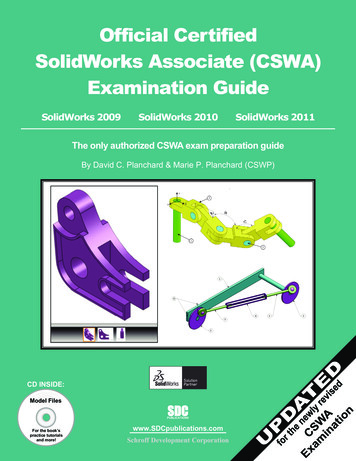
SOLIDWORKSTEACHER TRAININGMANUALCreated BySolid Solutions Ireland
Solid SolutionsIRELANDTable of ContentsPage1.0 Introduction 32.0 What is SolidWorks?.143.0 Create a Part .174.0 Create a drawing 325.0 Create an Assembly .386.0 Exercises 44Solid Solutions Ireland: Arena House, Arena Road, Sandford, Dublin 18.Phone: 01-2130716, Fax: 01-2130818, Email; info@solidsolutions.ie2
Solid SolutionsIRELAND1.0 IntroductionSolid Solutions Ireland: Arena House, Arena Road, Sandford, Dublin 18.Phone: 01-2130716, Fax: 01-2130818, Email; info@solidsolutions.ie3
Solid SolutionsIRELAND1.0 IntroductionAs your first step to mastering the use of solid works we are going to review the user interface or theSolidWorks window (See Fig 1.0 page 2). To begin, using the left mouse button double click on theSolidWorks icon on the PC desktop screen to open the program. If there is no icon visible the programcan be started through Start - All Programs – SolidWorks 2006. You can access commands inSolidWorks using menus, toolbars and the mouse. The SolidWorks interface is dynamic in thatdifferent toolbars and menus appear depending on the active document type.1.1 Document WindowsThe format of the SolidWorks window reflects that of windows itself. The same is true for anySolidWorks document. Once opened a document appears split into two panels. The right is the graphicswindow, where your model or drawing appears. You can create and manipulate the document in thegraphics window. The left panel contains the following SolidWorks document windows:FeatureManager design tree: Similar to the windows explorer tree it lists the structure of the part,assembly or drawing.PropertyManager: Appears in the left panel when you select many of the SolidWorks commands suchas sketches, fillet features and so on. The PropertyManager displays selection icons to enter relevantcommand options and boxes/fields to enable the user to enter relevant design and data parameters.ConfigurationManager: Appears in place of the FeatureManager design tree. Helps create, select andview multiple configurations (variations of parts and assemblies in a single document).Solid Solutions Ireland: Arena House, Arena Road, Sandford, Dublin 18.Phone: 01-2130716, Fax: 01-2130818, Email; info@solidsolutions.ie4
Solid SolutionsIRELAND1.2 The SolidWorks window18910 11 133122423 22215Figure 1.0: SolidWorks display commandsrelevant to the document type14 18176719 20The Main elements of the SolidWorks user interface are as follows (see Figure 1.0 for thecorresponding item numbers):1.Title bar: Displays the name of the active document and active document window with a blue(default color) title bar. Inactive document windows are shown with a grey title bar. If youhaven’t saved any changes to a document, you see a * after the document name.2.Main Menu: A set of drop down menus (File, Edit, View, and so on) across the top of the userinterface. The menu bar contents are task dependent based on the active document type.SolidWorks toolbars display these functions whereas the menu bar contains the complete set.3.Standard toolbar: Found just beneath the main menu this toolbar is consists of a set of themost commonly used command buttons.4.5.View toolbar: Features a series of commonly used command buttons that allow you to zoom,rotate and view the part in different orientations.Minimize window: Shrinks the document window.6.Maximize window: Enlarges the viewing window to full-size.7.Close window: Closes solid works. If you have made any changes to you documents,SolidWorks prompts you to save the document.Solid Solutions Ireland: Arena House, Arena Road, Sandford, Dublin 18.Phone: 01-2130716, Fax: 01-2130818, Email; info@solidsolutions.ie5
Solid SolutionsIRELAND8.Command Manager: A dynamic toolbar that lists the command buttons for the type ofdocument you are working on.9.FeatureManager design tree tab: Displays the FeatureManager design tree.10. PropertyManager: Appears in the left panel when you select many of the SolidWorkscommands such as sketches, fillet features and so on. The PropertyManager displays selectionicons to enter relevant command options and boxes/fields to enable the user to enter relevantdesign and data parameters.11. ConfigurationManager tab: Appears in place of the FeatureManager design tree. Helps create,select and view multiple configurations (variations of parts and assemblies in a singledocument).12. FeatureManager design tree: Similar to the windows explorer tree it lists the structure of thepart, assembly or drawing.13. Show display pane: Expands or collapses the display pane.14. Graphics area: Displays the part assembly or drawing.15. Pointer: Indicates the position of the mouse and lets you select items within the user interface(not shown on Fig 1.0)16. Tool tip: A pop up informational message about a feature or function. It appears when youhover the pointer over an object. It disappears after a few seconds (not shown on Fig 1.0).17. Status bar: Gives more complex explanation of the selected function.18. Status bar: Indicates whether it is a drawing, part or assembly that you are editing.19. Quick tips help: Indicates with a question mark button whether Quick Tips is on or off. Clickthe icon to toggle20. Resize window: Enables resizing (by clicking and dragging) the window if it isn’t alreadymaximized.21. SolidWorks resources: Click to open the SolidWorks Resources tab, which contains links toresources, tutorials, tips of the day and also command buttons to open or create SolidWorksdocuments.22. Design Library: Click to open the design library. Inside you see the Design Library, Toolboxand 3D Content Central each which contain many standard design elements you can drag anddrop into your design.23. File Explorer: Duplicates Windows Explorer in your computer. Lists recently openeddocuments and currently opened documents. You can drag documents from here into thegraphics area.Solid Solutions Ireland: Arena House, Arena Road, Sandford, Dublin 18.Phone: 01-2130716, Fax: 01-2130818, Email; info@solidsolutions.ie6
Solid SolutionsIRELAND1.2.1 The FeatureManager design treeOn the left side of the SolidWorks document window the FeatureManager design tree providesWindows Explorer-type selection and editing access to all the entities in your active document. Thetype of entities the design tree is populated with varies depending on the active document type fromfeatures and sketches for part documents to drawing views for a drawing and parts/subassemblies in anassembly.Key advantages offered by the FeatureManager design tree: Shows the order in which the elements were created with the oldest at the top Links to the graphics paneAllows selection/highlighting of an object by clicking/hovering the pointer over theappropriate element in either the design tree or graphics area. Displays graphical feedback that displays feature or component characteristics:For Example if the component is suppressed, it appears in grey. Allows you to see the contents of the folders in the tree:You can click or – to maximize or minimize the folder. Gives you access to quick functions when you right click:The functions displayed will depend on the object and document type.Fig 1.1: The CommandManager1.2.2 The Command ManagerLocated just below the standard tool bar in the top left hand corner of the document window, is theCommandManager, a smart toolbar that displays the menus you need for the task at hand. TheCommandManager is divided into two areas: the control area made up a selection of buttons any ofwhich selected displays a toolbar in the toolbar area (directly to the right of the control area as shownabove). For example, if you select the Features button, the Feature commands display in the toolbararea (Extruded base/boss, extruded cut and so on).The CommandManager makes efficient use of the space onscreen by embedding a number of toolbarsin just one. As a result this minimizes the number of menu picks, mouse movements and overall allowsthe user to work faster and more efficiently.1.3 View and OrientationA set of predefined views can be selected through the Standard view toolbar, a flyout (similar to a dropdown Menu) tool bar that is embedded in the View toolbar. If you click the Standard View button inthe View toolbar, you get a pull-down menu of several commands that represent standard engineeringviews. This enables the user to select views such as Side, Front, Top, Right and Bottom as well asperspectives: Isometric, Trimetric and Dimetric which vary in viewing.1.3.1 OrientationThe orientation section of the View toolbar offers several tools to enable the user to manuallymanipulate the orientation of a model. These manipulation tools include the following:Zoom to Fit: Zooms in or out so the entire model is visible.Solid Solutions Ireland: Arena House, Arena Road, Sandford, Dublin 18.Phone: 01-2130716, Fax: 01-2130818, Email; info@solidsolutions.ie7
Solid SolutionsIRELANDZoom to Area: Zooms in on a portion of the view that you select by dragging abounding box. The centre of the box is marked with plus ( ) sign.Zoom In/Out: Zooms in as you press and hold the left mouse button and drag themouse up. Zooms out as you drag the mouse down.Zoom to Selection: Zooms to the size of a selected entity.Rotate View: Rotates the view as you press and hold the left mouse button and dragthe mouse around the screen.Roll View: Rotates the view about an axis normal to the screen as you press and holdthe left mouse button and drag the mouse around the screen.Pan View: Scrolls the view so the model moves as you drag the mouse.1.3.2 Display ModesThe third section of the View toolbar offers the following display modes for model and drawing viewin drawing documents. These tools include the following:ShadedShaded with EdgesHidden Lines RemovedHidden Lines VisibleWireframe (Displays all edges of the model)Section ViewShadedShaded withEdgesHidden LinesHidden LinesWireframeRemovedVisibleFig 1.2: Display ModesSolid Solutions Ireland: Arena House, Arena Road, Sandford, Dublin 18.Phone: 01-2130716, Fax: 01-2130818, Email; info@solidsolutions.ie8
Solid SolutionsIRELANDFig 1.3: Section View and PropertyManager1.4 Control1.4.1 Mouse buttonsSolidWorks uses three mouse buttons to access features, select objects and perform tasks:Left:Selects menu items, entities in the graphics area, and objects in theFeatureManager design tree.To select an entity click on the entity in the graphics window or in the feature manager design tree.Selected objects become highlighted in both the graphics area and FeatureManager design tree. Toselect multiple entities hold down the Ctrl button while continuing to click on the objects to beselected. To select a group of objects hold down the mouse button and drag a window around theobjects. To deselect all objects click anywhere in the document window outside the part or assembly.Right:Displays context sensitive options and shortcut menus.Middle:Rotate:Hold down button and move mouse. To rotate about a vertex edge or axis (other than theorigin) click the middle mouse button on the geometry then hold and move the mouse.Pan:Hold Ctrl button while holding down button and move the mouseZoom:Position cursor over the chosen position in the graphics window and hold shift and mousebutton or if available spin roller button toward you to zoom out and reverse to zoom in.Solid Solutions Ireland: Arena House, Arena Road, Sandford, Dublin 18.Phone: 01-2130716, Fax: 01-2130818, Email; info@solidsolutions.ie9
Solid SolutionsIRELAND1.4.2 Keyboard ShortcutsListed below are the predefined keyboard shortcuts options:Arrow Keys . . . . . . . . . . . . . . . . Rotate the viewShift Arrow Keys . . . . . . . . . . .Rotate the view in 90 incrementsAlt Left or Right Arrow Keys .Rotate about normal to the screenCtrl Arrow Keys . . . . . . . . . . .Move the viewShift z . . . . . . . . . . . . . . . . . . . .Zoom Inz. . . . . . . . . . . . . . . . . . . . . . . . . . Zoom Outf . . . . . . . . . . . . . . . . . . . . . . . . . . Zoom to FitCtrl 1 . . . . . . . . . . . . . . . . . . . . . Front OrientationCtrl 2 . . . . . . . . . . . . . . . . . . . . . Back OrientationCtrl 3 . . . . . . . . . . . . . . . . . . . . . Left OrientationCtrl 4 . . . . . . . . . . . . . . . . . . . . . Right OrientationCtrl 5 . . . . . . . . . . . . . . . . . . . . . Top OrientationCtrl 6 . . . . . . . . . . . . . . . . . . . . . Bottom OrientationCtrl 7 . . . . . . . . . . . . . . . . . . . . . Isometric OrientationCtrl 8 . . . . . . . . . . . . . . . . . . . . . View Normal ToSpacebar . . . . . . . . . . . . . . . . . .View Orientation dialogCtrl . . . . . . . . . . . . . . . . . . . . . . . Hold and select multiple items with mouse buttonCtrl c . . . . . . . . . . . . . . . . . . . . . Copy selected entity/itemCtrl z . . . . . . . . . . . . . . . . . . . . . UndoCtrl y . . . . . . . . . . . . . . . . . . . . . RedoCtrl Tab . . . . . . . . . . . . . . . . . . .Switch between documentsAlt drag . . . . . . . . . . . . . . . . . . .Select anywhere in a drawing viewShift drag . . . . . . . . . . . . . . . . .Maintains distance between drawing views while draggingCtrl R . . . . . . . . . . . . . . . . . . . . .RedrawCtrl B . . . . . . . . . . . . . . . . . . . . .Rebuild1.5 CustomisationFig 1.4: Located on the tools menu the options dialogue box allows you to customize the SolidWorkssoftwareSolid Solutions Ireland: Arena House, Arena Road, Sandford, Dublin 18.Phone: 01-2130716, Fax: 01-2130818, Email; info@solidsolutions.ie10
Solid SolutionsIRELAND1.5.1 Customizing the SolidWorks windowSystem optionsThe options grouped under the heading System Options are saved on your system and affect everydocument you open in your SolidWorks session. System settings
SolidWorks window (See Fig 1.0 page 2). To begin, using the left mouse button double click on the SolidWorks icon on the PC desktop screen to open the program. If there is no icon visible the program can be started through Start - All Programs – SolidWorks 2006. You can access commands in SolidWorks using menus, toolbars and the mouse. The SolidWorks interface is dynamic in that


