Transcription
Quartus II Introduction Using VHDL DesignRThis tutorial presents an introduction to the Quartus II CAD system. It gives a general overview of a typical CAD flow for designing circuits that are implemented by using FPGA devices, and shows how this flow isrealized in the Quartus II software. The design process is illustrated by giving step-by-step instructions for usingthe Quartus II software to implement a very simple circuit in an Altera FPGA device.The Quartus II system includes full support for all of the popular methods of entering a description of thedesired circuit into a CAD system. This tutorial makes use of the VHDL design entry method, in which the userspecifies the desired circuit in the VHDL hardware description language. Two other versions of this tutorial arealso available; one uses the Verilog hardware description language and the other is based on defining the desiredcircuit in the form of a schematic diagram.The last step in the design process involves configuring the designed circuit in an actual FPGA device. Toshow how this is done, it is assumed that the user has access to the Altera DE2 Development and Education boardconnected to a computer that has Quartus II software installed. A reader who does not have access to the DE2board will still find the tutorial useful to learn how the FPGA programming and configuration task is performed.The screen captures in the tutorial were obtained using the Quartus II version 7.1; if other versions of thesoftware are used, some of the images may be slightly different.Contents:Typical CAD flowGetting startedStarting a New ProjectVHDL Design EntryCompiling the DesignPin AssignmentSimulating the Designed CircuitProgramming and Configuring the FPGA DeviceTesting the Designed Circuit1
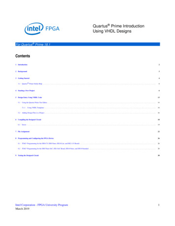
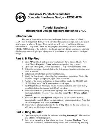
Computer Aided Design (CAD) software makes it easy to implement a desired logic circuit by using a programmable logic device, such as a field-programmable gate array (FPGA) chip. A typical FPGA CAD flow isillustrated in Figure 1.Design EntrySynthesisFunctional SimulationNoDesign correct?YesFittingTiming Analysis and SimulationNoTiming requirements met?YesProgramming and ConfigurationFigure 1. Typical CAD flow.The CAD flow involves the following steps: Design Entry – the desired circuit is specified either by means of a schematic diagram, or by using ahardware description language, such as VHDL or Verilog Synthesis – the entered design is synthesized into a circuit that consists of the logic elements (LEs) providedin the FPGA chip Functional Simulation – the synthesized circuit is tested to verify its functional correctness; this simulationdoes not take into account any timing issues2
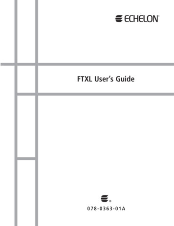
Fitting – the CAD Fitter tool determines the placement of the LEs defined in the netlist into the LEs inan actual FPGA chip; it also chooses routing wires in the chip to make the required connections betweenspecific LEs Timing Analysis – propagation delays along the various paths in the fitted circuit are analyzed to providean indication of the expected performance of the circuit Timing Simulation – the fitted circuit is tested to verify both its functional correctness and timing Programming and Configuration – the designed circuit is implemented in a physical FPGA chip by programming the configuration switches that configure the LEs and establish the required wiring connectionsThis tutorial introduces the basic features of the Quartus II software. It shows how the software can be used todesign and implement a circuit specified by using the VHDL hardware description language. It makes use of thegraphical user interface to invoke the Quartus II commands. Doing this tutorial, the reader will learn about: Creating a project Design entry using VHDL code Synthesizing a circuit specified in VHDL code Fitting a synthesized circuit into an Altera FPGA Assigning the circuit inputs and outputs to specific pins on the FPGA Simulating the designed circuit Programming and configuring the FPGA chip on Altera’s DE2 board1Getting StartedEach logic circuit, or subcircuit, being designed with Quartus II software is called a project. The software workson one project at a time and keeps all information for that project in a single directory (folder) in the file system.To begin a new logic circuit design, the first step is to create a directory to hold its files. To hold the design filesfor this tutorial, we will use a directory introtutorial. The running example for this tutorial is a simple circuit fortwo-way light control.Start the Quartus II software. You should see a display similar to the one in Figure 2. This display consistsof several windows that provide access to all the features of Quartus II software, which the user selects with thecomputer mouse. Most of the commands provided by Quartus II software can be accessed by using a set of menusthat are located below the title bar. For example, in Figure 2 clicking the left mouse button on the menu namedFile opens the menu shown in Figure 3. Clicking the left mouse button on the entry Exit exits from Quartus IIsoftware. In general, whenever the mouse is used to select something, the left button is used. Hence we will notnormally specify which button to press. In the few cases when it is necessary to use the right mouse button, it willbe specified explicitly.3
Figure 2. The main Quartus II display.Figure 3. An example of the File menu.4
For some commands it is necessary to access two or more menus in sequence. We use the convention Menu1 Menu2 Item to indicate that to select the desired command the user should first click the left mouse buttonon Menu1, then within this menu click on Menu2, and then within Menu2 click on Item. For example, File Exit uses the mouse to exit from the system. Many commands can be invoked by clicking on an icon displayed inone of the toolbars. To see the command associated with an icon, position the mouse over the icon and a tooltipwill appear that displays the command name.1.1Quartus II Online HelpQuartus II software provides comprehensive online documentation that answers many of the questions that mayarise when using the software. The documentation is accessed from the menu in the Help window. To get someidea of the extent of documentation provided, it is worthwhile for the reader to browse through the Help menu.For instance, selecting Help How to Use Help gives an indication of what type of help is provided.The user can quickly search through the Help topics by selecting Help Search, which opens a dialog boxinto which key words can be entered. Another method, context-sensitive help, is provided for quickly findingdocumentation for specific topics. While using most applications, pressing the F1 function key on the keyboardopens a Help display that shows the commands available for the application.2Starting a New ProjectTo start working on a new design we first have to define a new design project. Quartus II software makes thedesigner’s task easy by providing support in the form of a wizard. Create a new project as follows:1. Select File New Project Wizard to reach the window in Figure 4, which asks for the name and directoryof the project.Figure 4. Creation of a new project.5
2. Set the working directory to be introtutorial; of course, you can use some other directory name of yourchoice if you prefer. The project must have a name, which is usually the same as the top-level design entitythat will be included in the project. Choose light as the name for both the project and the top-level entity, asshown in Figure 4. Press Next. Since we have not yet created the directory introtutorial, Quartus II softwaredisplays the pop-up box in Figure 5 asking if it should create the desired directory. Click Yes, which leadsto the window in Figure 6.Figure 5. Quartus II software can create a new directory for the project.Figure 6. The wizard can include user-specified design files.3. The wizard makes it easy to specify which existing files (if any) should be included in the project. Assumingthat we do not have any existing files, click Next, which leads to the window in Figure 7.6
Figure 7. Choose the device family and a specific device.4. We have to specify the type of device in which the designed circuit will be implemented. Choose CycloneTMII as the target device family. We can let Quartus II software select a specific device in the family, or we canchoose the device explicitly. We will take the latter approach. From the list of available devices, choose thedevice called EP2C35F672C6 which is the FPGA used on Altera’s DE2 board. Press Next, which opens thewindow in Figure 8.Figure 8. Other EDA tools can be specified.7
5. The user can specify any third-party tools that should be used. A commonly used term for CAD softwarefor electronic circuits is EDA tools, where the acronym stands for Electronic Design Automation. This termis used in Quartus II messages that refer to third-party tools, which are the tools developed and marketedby companies other than Altera. Since we will rely solely on Quartus II tools, we will not choose any othertools. Press Next.6. A summary of the chosen settings appears in the screen shown in Figure 9. Press Finish, which returns tothe main Quartus II window, but with light specified as the new project, in the display title bar, as indicatedin Figure 10.Figure 9. Summary of the project settings.8
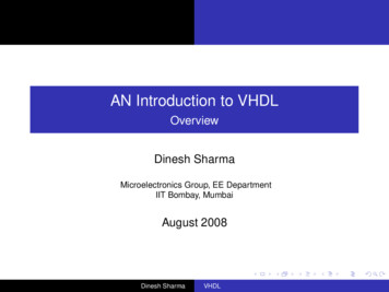
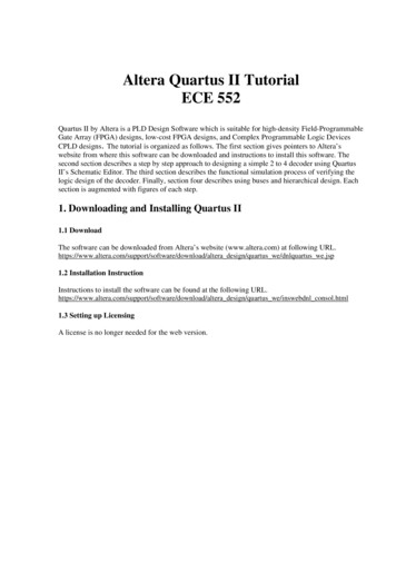
Figure 10. The Quartus II display for the created project.3Design Entry Using VHDL CodeAs a design example, we will use the two-way light controller circuit shown in Figure 11. The circuit can be usedto control a single light from either of the two switches, x1 and x2 , where a closed switch corresponds to the logicvalue 1. The truth table for the circuit is also given in the figure. Note that this is just the Exclusive-OR functionof the inputs x1 and x2 , but we will specify it using the gates shown.x1fx2x1 x2f0 000 111 011 10Figure 11. The light controller circuit.The required circuit is described by the VHDL code in Figure 12. Note that the VHDL entity is called light tomatch the name given in Figure 5, which was specified when the project was created. This code can be typed intoa file by using any text editor that stores ASCII files, or by using the Quartus II text editing facilities. While thefile can be given any name, it is a common designers’ practice to use the same name as the name of the top-levelVHDL entity. The file name must include the extension vhd, which indicates a VHDL file. So, we will use thename light.vhd.9
LIBRARY ieee ;USE ieee.std logic 1164.all ;ENTITY light ISPORT ( x1, x2 : INSTD LOGIC ;f: OUT STD LOGIC ) ;END light ;ARCHITECTURE LogicFunction OF light ISBEGINf (x1 AND NOT x2) OR (NOT x1 AND x2);END LogicFunction ;Figure 12. VHDL code for the circuit in Figure 11.3.1Using the Quartus II Text EditorThis section shows how to use the Quartus II Text Editor. You can skip this section if you prefer to use some othertext editor to create the VHDL source code file, which we will name light.vhd.Select File New to get the window in Figure 13, choose VHDL File, and click OK. This opens the TextEditor window. The first step is to specify a name for the file that will be created. Select File Save As to openthe pop-up box depicted in Figure 14. In the box labeled Save as type choose VHDL File. In the box labeledFile name type light. Put a checkmark in the box Add file to current project. Click Save, which puts the fileinto the directory introtutorial and leads to the Text Editor window shown in Figure 15. Maximize the Text Editorwindow and enter the VHDL code in Figure 12 into it. Save the file by typing File Save, or by typing theshortcut Ctrl-s.Figure 13. Choose to prepare a VHDL file.10
Figure 14. Name the file.Figure 15. Text Editor window.Most of the commands available in the Text Editor are self-explanatory. Text is entered at the insertion point,which is indicated by a thin vertical line. The insertion point can be moved either by using the keyboard arrowkeys or by using the mouse. Two features of the Text Editor are especially convenient for typing VHDL code.First, the editor can display different types of VHDL statements in different colors, which is the default choice.Second, the editor can automatically indent the text on a new line so that it matches the previous line. Such optionscan be controlled by the settings in Tools Options Text Editor.3.1.1Using VHDL TemplatesThe syntax of VHDL code is sometimes difficult for a designer to remember. To help with this issue, the TextEditor provides a collection of VHDL templates. The templates provide examples of various types of VHDLstatements, such as an ENTITY declaration, a CASE statement, and assignment statements. It is worthwhileto browse through the templates by selecting Edit Insert Template VHDL to become familiar with thisresource.3.2Adding Design Files to a ProjectAs we indicated when discussing Figure 6, you can tell Quartus II software which design files it should use as partof the current project. To see the list of files already included in the light project, select Assignments Settings,which leads to the window in Figure 16. As indicated on the left side of the figure, click on the item Files. Analternative way of making this selection is to choose Project Add/Remove Files in Project.11
Figure 16. Settings window.If you used the Quartus II Text Editor to create the file and checked the box labeled Add file to currentproject, as described in Section 3.1, then the light.vhd file is already a part of the project and will be listed in thewindow in Figure 16. Otherwise, the file must be added to the project. So, if you did not use the Quartus II TextEditor, then place a copy of the file light.vhd, which you created using some other text editor, into the directoryintrotutorial. To add this file to the project, click on the File name: button in Figure 16 to get the pop-up windowin Figure 17. Select the light.vhd file and click Open. The selected file is now indicated in the Files window ofFigure 16. Click OK to include the light.vhd file in the project. We should mention that in many cases the QuartusII software is able to automatically find the right files to use for each entity referenced in VHDL code, even if thefile has not been explicitly added to the project. However, for complex projects that involve many files it is a gooddesign practice to specifically add the needed files to the project, as described above.Figure 17. Select the file.12
4Compiling the Designed CircuitThe VHDL code in the file light.vhd is processed by several Quartus II tools that analyze the code, synthesizethe circuit, and generate an implementation of it for the target chip. These tools are controlled by the applicationprogram called the Compiler.thatRun the Compiler by selecting Processing Start Compilation, or by clicking on the toolbar iconlooks like a purple triangle. As the compilation moves through various stages, its progress is reported in a windowon the left side of the Quartus II display. Successful (or unsuccessful) compilation is indicated in a pop-up box.Acknowledge it by clicking OK, which leads to the Quartus II display in Figure 18. In the message window, at thebottom of the figure, various messages are displayed. In case of errors, there will be appropriate messages given.When the compilation is finished, a compilation report is produced. A window showing this report is openedautomatically, as seen in Figure 18. The window can be resized, maximized, or closed in the normal way, and it.can be opened at any time either by selecting Processing Compilation Report or by clicking on the iconThe report includes a number of sections listed on the left side of its window. Figure 18 displays the CompilerFlow Summary section, which indicates that only one logic element and three pins are needed to implement thistiny circuit on the selected FPGA chip.Figure 18. Display after a successful compilation.13
4.1ErrorsQuartus II software displays messages produced during compilation in the Messages window. If the VHDL designfile is correct, one of the messages will state that the compilation was successful and that there are no errors.If the Compiler does not report zero errors, then there is at least one mistake in the VHDL code. In this casea message corresponding to each error found will be displayed in the Messages window. Double-clicking on anerror message will highlight the offending statement in the VHDL code in the Text Editor window. Similarly, theCompiler may display some warning messages. Their details can be explored in the same way as in the case oferror messages. The user can obtain more information about a specific error or warning message by selecting themessage and pressing the F1 function key.To see the effect of an error, open the file light.vhd. Remove the semicolon in the statement that defines thefunction f , illustrating a typographical error that is easily made. Compile the erroneous design file by clicking onicon. A pop-up box will ask if the changes made to the light.vhd file should be saved; click Yes. Afterthetrying to compile the circuit, Quartus II software will display a pop-up box indicating that the compilation was notsuccessful. Acknowledge it by clicking OK. The compilation report summary, given in Figure 19, now confirmsthe failed result. Expand the Analysis & Synthesis part of the report and then select Messages to have themessages displayed as shown in Figure 20. Double-click on the first error message. Quartus II software respondsby opening the light.vhd file and highlighting the statement which is affected by the error, as shown in Figure 21.Correct the error and recompile the design.Figure 19. Compilation report for the failed design.Figure 20. Error messages.14
Figure 21. Identifying the location of the error.5Pin AssignmentDuring the compilation above, the Quartus II Compiler was free to choose any pins on the selected FPGA to serveas inputs and outputs. However, the DE2 board has hardwired connections between the FPGA pins and the othercomponents on the board. We will use two toggle switches, labeled SW0 and SW1 , to provide the external inputs,x1 and x2 , to our example circuit. These switches are connected to the FPGA pins N25 and N26, respectively. Wewill connect the output f to the green light-emitting diode labeled LEDG0 , which is hardwired to the FPGA pinAE22.Pin assignments are made by using the Assignment Editor. Select Assignments Assignment Editor toreach the window in Figure 22. Under Category select Pin. Double-click on the entry new which ishighlighted in blue in the column labeled To. The drop-down menu in Figure 23 will appear. Click on x1 as thefirst pin to be assigned; this will enter x1 in the displayed table. Follow this by double-clicking on the box to theright of this new x1 entry, in the column labeled Location. Now, the drop-down menu in Figure 24 appears. Scrolldown and select PIN N25. Instead of scrolling down the menu to find the desired pin, you can just type the nameof the pin (N25) in the Location box. Use the same procedure to assign input x2 to pin N26 and output f to pinAE22, which results in the image in Figure 25. To save the assignments made, choose File Save. You can alsosimply close the Assignment Editor window, in which case a pop-up box will ask if you want to save the changesto assignments; click Yes. Recompile the circuit, so that it will be compiled with the correct pin assignments.Figure 22. The Assignment Editor window.15
Figure 23. The drop-down menu displays the input and output names.Figure 24. The available pins.Figure 25. The complete assignment.The DE2 board has fixed pin assignments. Having finished one design, the user will want to use the samepin assignment for subsequent designs. Going through the procedure described above becomes tedious if thereare many pins used in the design. A useful Quartus II feature allows the user to both export and import the pinassignments from a special file format, rather than creating them manually using the Assignment Editor. A simplefile format that can be used for this purpose is the comma separated value (CSV) format, which is a common textfile format that contains comma-delimited values. This file format is often used in conjunction with the MicrosoftExcel spreadsheet program, but the file can also be created by hand using any plain ASCII text editor. The formatfor the file for our simple project is16
To, Locationx1, PIN N25x2, PIN N26f, PIN AE22By adding lines to the file, any number of pin assignments can be created. Such csv files can be imported into anydesign project.If you created a pin assignment for a particular project, you can export it for use in a different project. To seehow this is done, open again the Assignment Editor to reach the window in Figure 25. Now, select File Exportwhich leads to the window in Figure 26. Here, the file light.csv is available for export. Click on Export. If younow look in the directory introtutorial, you will see that the file light.csv has been created.Figure 26. Exporting the pin assignment.You can import a pin assignment by choosing Assignments Import Assignments. This opens the dialogue in Figure 27 to select the file to import. Type the name of the file, including the csv extension and the fullpath to the directory that holds the file, in the File Name box and press OK. Of course, you can also browse to findthe desired file.Figure 27. Importing the pin assignment.17
For convenience when using large designs, all relevant pin assignments for the DE2 board are given in the filecalled DE2 pin assignments.csv in the directory DE2 tutorials\design files, which is included on the CD-ROMthat accompanies the DE2 board and can also be found on Altera’s DE2 web pages. This file uses the names foundin the DE2 User Manual. If we wanted to make the pin assignments for our example circuit by importing thisfile, then we would have to use the same names in our VHDL design file; namely, SW(0), SW(1) and LEDG(0)for x1, x2 and f, respectively. Since these signals are specified in the DE2 pin assignments.csv file as elementsof arrays SW and LEDG, we must refer to them in the same way in the VHDL design file. For example, in theDE2 pin assignments.csv file the 18 toggle switches are called SW[17] to SW[0]; since VHDL uses parenthesesrather than square brackets, these switches are referred to as SW(17) to SW(0). They can also be referred to as anarray SW(17 downto 0).6Simulating the Designed CircuitBefore implementing the designed circuit in the FPGA chip on the DE2 board, it is prudent to simulate it toascertain its correctness. Quartus II software includes a simulation tool that can be used to simulate the behaviorof a designed circuit. Before the circuit can be simulated, it is necessary to create the desired waveforms, calledtest vectors, to represent the input signals. It is also necessary to specify which outputs, as well as possible internalpoints in the circuit, the designer wishes to observe. The simulator applies the test vectors to a model of theimplemented circuit and determines the expected response. We will use the Quartus II Waveform Editor to drawthe test vectors, as follows:1. Open the Waveform Editor window by selecting File New, which gives the window shown in Figure 28.Click on the Other Files tab to reach the window displayed in Figure 29. Choose Vector Waveform Fileand click OK.Figure 28. Need to prepare a new file.18
Figure 29. Choose to prepare a test-vector file.2. The Waveform Editor window is depicted in Figure 30. Save the file under the name light.vwf; note that thischanges the name in the displayed window. Set the desired simulation to run from 0 to 200 ns by selectingEdit End Time and entering 200 ns in the dialog box that pops up. Selecting View Fit in Windowdisplays the entire simulation range of 0 to 200 ns in the window, as shown in Figure 31. You may wish toresize the window to its maximum size.Figure 30. The Waveform Editor window.19
Figure 31. The augmented Waveform Editor window.3. Next, we want to include the input and output nodes of the circuit to be simulated. Click Edit Insert Insert Node or Bus to open the window in Figure 32. It is possible to type the name of a signal (pin) intothe Name box, but it is easier to click on the button labeled Node Finder to open the window in Figure33. The Node Finder utility has a filter used to indicate what type of nodes are to be found. Since we areinterested in input and output pins, set the filter to Pins: all. Click the List button to find the input andoutput nodes as indicated on the left side of the figure.Figure 32. The Insert Node or Bus dialogue.Figure 33. Selecting nodes to insert into the Waveform Editor.20
Click on the x1 signal in the Nodes Found box in Figure 33, and then click the sign to add it to the SelectedNodes box on the right side of the figure. Do the same for x2 and f. Click OK to close the Node Finderwindow, and then click OK in the window of Figure 32. This leaves a fully displayed Waveform Editorwindow, as shown in Figure 34. If you did not select the nodes in the same order as displayed in Figure 34,it is possible to rearrange them. To move a waveform up or down in the Waveform Editor window, click onthe node name (in the Name column) and release the mouse button. The waveform is now highlighted toshow the selection. Click again on the waveform and drag it up or down in the Waveform Editor.Figure 34. The nodes needed for simulation.4. We will now specify the logic values to be used for the input signals x1 and x2 during simulation. The logicvalues at the output f will be generated automatically by the simulator. To make it easy to draw the desiredwaveforms, the Waveform Editor displays (by default) vertical guidelines and provides a drawing featurethat snaps on these lines (which can otherwise be invoked by choosing View Snap to Grid). Observe alsoa solid vertical line, which can be moved by pointing to its top and dragging it horizontally. This referenceline is used in analyzing the timing of a circuit; move it to the time 0 position. The waveforms can bedrawn using the Selection Tool, which is activated by selecting the iconEditing Tool, which is activated by the iconin the toolbar, or the Waveform.To simulate the behavior of a large circuit, it is necessary to apply a sufficient number of input valuations andobserve the expected values of the outputs. In a large circuit the number of possible input valuations maybe huge, so in practice we choose a relatively small (but representative) sample of these input valuations.However, for our tiny circuit we can simulate all four input valuations given in Figure 11. We will use four50-ns time intervals to apply the four test vectors.We can generate the desired input waveforms as follows. Click on the waveform name for the x1 node.Once a waveform is selected, the editing commands in the Waveform Editor can be used to draw the desiredwaveforms. Commands are available for setting a selected signal to 0, 1, unknown (X), high impedance (Z),don’t care (DC), inverting its existing value (INV), or defining a clock waveform. Each command can beactivated by using the Edit Value command, or via the toolbar for the Waveform Editor. The Edit menucan also be opened by right-clicking on a waveform name.Set x1 to 0 in the time interval 0 to 100 ns, which is probably already set by default. Next, set x1 to 1 in thetime interval 100 to 200 ns. Do this by pressing the mouse at the start of the interval and dragging it to itsend, which highlights the selected interval, and choosing the logic value 1 in the toolbar. Make x2 1 from50 to 100 ns and also from 150 to 200 ns, which corresponds to the truth table in Figure 11. This should21
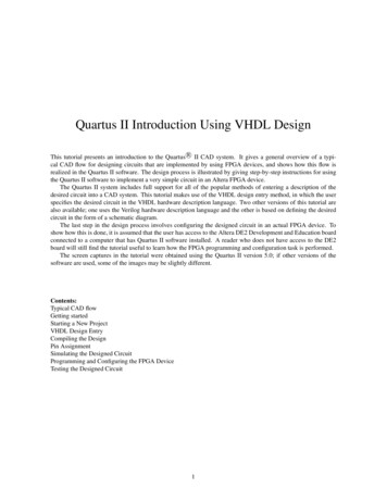
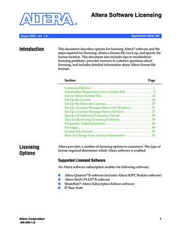
produce the image in Figure 35. Observe that the output f is displayed as having an unknown value at thistime, which is indicated by a hashed pattern; its value will be determined during simulation. Save the file.Figure 35. Setting of test values.6.1Performing the SimulationA designed circuit can be simulated in two ways. The simplest way is to assume that logic elements and interconnection wires in the FPGA are perfect, thus causing no delay in propagation of signals through the circuit. Thisis called functional simulation. A more complex alternative is to take all propagation delays into account, whichleads to timing simulation. Typically, functional simulation is used to verify the functional correctness of a circuitas it is being designed. This takes much less time, because the simulation can be performed simply by using thelogic expressions that define the circuit.6.1.1Functional SimulationTo perform the functional simulation, select Assignments Settings to open the Settings window. On the leftside of this window click on Simulator Settings to display the window in Figure 36, choose Functional as thesimulation mode, and click OK. The Quartus II simulator takes the inputs and generates the outputs defined in thelight.vwf file. Before running the functional simulation it is necessary to create the required netlist, which is doneby selecting Processing Generate Functional Simulation Netlist. A simulation run is started by Processing Start Simulation, or by using the icon . At the end of the simulation, Quartus II software indicates itssuccessful completion and displays a Simulation Report illustrated in Figure 37. If your report window does notshow the entire simulation time range, click on the report window to select it and choose View Fit in Window.Observe that the output f is as specified in the truth table of Figure 11.22
Figure 36. Specifying the simulation mode.Figure 37. The result of functional simulation.6.1.2Timing SimulationHaving ascertained that the designed circui
Quartus II Introduction Using VHDL Design This tutorial presents an introduction to the Quartus R II CAD system. It gives a general overview of a typi-cal CAD flow for designing circuits that are implemented by using FPGA devices, and shows how this flow is realized in the Quartus II software. The design process is illustrated by giving step .