Transcription
SOLIDWORKS 2020 Tutorial A Step-by-Step Project Based ApproachUtilizing 3D Solid ModelingDavid C. Planchard, CSWP,SOLIDWORKS Accredited EducatorSDCP U B L I C AT I O N SBetter Textbooks. Lower Prices.www.SDCpublications.com
Visit the following websites to learn more about this book:Powered by TCPDF (www.tcpdf.org)
SOLIDWORKS 2020 TutorialOverview of SOLIDWORKS and the User InterfaceChapter 1Overview of SOLIDWORKS 2020 and the User InterfaceBelow are the desired outcomes and usage competencies based on the completion ofChapter 1.Desired Outcomes: A comprehensiveunderstanding of theSOLIDWORKS 2020 UserInterface (UI) andCommandManager.Usage Competencies: Ability to establish a SOLIDWORKS session. Aptitude to utilize the following items: Menubar toolbar, Menu bar menu, Drop-downmenus, Context toolbars, Consolidated dropdown toolbars, System feedback icons,Confirmation Corner, Heads-up View toolbar,Document Properties and more. Open a new and existing SOLIDWORKS part. Knowledge to zoom, rotate and maneuver athree-button mouse in the SOLIDWORKSGraphics window.PAGE 1 - 1
Overview of SOLIDWORKS and the User InterfaceNotes:PAGE 1 - 2SOLIDWORKS 2020 Tutorial
SOLIDWORKS 2020 TutorialOverview of SOLIDWORKS and the User InterfaceChapter 1 - Overview of SOLIDWORKS 2020 and the User InterfaceChapter ObjectiveProvide a comprehensive understanding of the SOLIDWORKS default User Interfaceand CommandManager: Menu bar toolbar, Menu bar menu, Drop-down menu, Rightclick Pop-up menus, Context toolbars/menus, Fly-out tool button, System feedback icons,Confirmation Corner, Heads-up View toolbar and more.On the completion of this chapter, you will be able to: Utilize the SOLIDWORKS Welcome dialog box. Establish a SOLIDWORKS session. Comprehend the SOLIDWORKS 2020 User Interface. Recognize the default Reference Planes in the FeatureManager. Open a new and existing SOLIDWORKS part. Utilize SOLIDWORKS Help and SOLIDWORKS Tutorials. Zoom, rotate and maneuver a three-button mouse in the SOLIDWORKS Graphicswindow.What is SOLIDWORKS ? SOLIDWORKS is a mechanical design automation software package used to buildparts, assemblies and drawings that takes advantage of the familiar Microsoft Windows graphical user interface. SOLIDWORKS is an easy to learn design and analysis tool (SOLIDWORKSSimulation, SOLIDWORKS Motion, SOLIDWORKS Flow Simulation,Sustainability, etc.), which makes it possible for designers to quickly sketch 2D and3D concepts, create 3D parts and assemblies and detail 2D drawings. Model dimensions in SOLIDWORKS are associative between parts, assemblies anddrawings. Reference dimensions are one-way associative from the part to the drawingor from the part to the assembly. This book is written for the beginner to intermediate user.PAGE 1 - 3
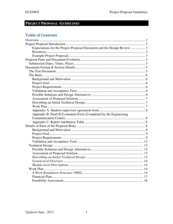
Overview of SOLIDWORKS and the User InterfaceSOLIDWORKS 2020 TutorialStart a SOLIDWORKS 2020 SessionStart a SOLIDWORKS 2020 session and familiarize yourself with the SOLIDWORKS UserInterface. As you read and perform the tasks in this chapter, you will obtain a sense of how touse the book and the structure. Actual input commands or required actions in the chapter aredisplayed in bold.The book does not cover starting a SOLIDWORKS session in detail for the first time. Adefault SOLIDWORKS installation presents you with several options. For additionalinformation, visit http://www.SOLIDWORKS.com.Activity: Start a SOLIDWORKS 2020 Session.Start a SOLIDWORKS 2020 session.1)Type SOLIDWORKS 2020 in the Search window.2)Click the SOLIDWORKS 2020 application (or if available,double-click the SOLIDWORKS icon on the desktop). TheSOLIDWORKS Welcome dialog box is displayedby default.The Welcome dialog box provides aconvenient way to open recent documents(Parts, Assemblies and Drawings), viewrecent folders, access SOLIDWORKSresources, and stay updated onSOLIDWORKS news.3)View your options. Do not open adocument at this time.4)If the Welcome dialog box is notdisplayed, click the Welcome toSOLIDWORKSicon from theStandard toolbar or click Help Welcome to SOLIDWORKS from theMain menu.PAGE 1 - 4
SOLIDWORKS 2020 TutorialOverview of SOLIDWORKS and the User InterfaceHome TabThe Home tab lets you open new and existingdocuments, view recent documents andfolders, and access SOLIDWORKSresources (Part, Assembly, Drawing,Advanced mode, Open).Recent TabThe Recent tab lets you view a longer list ofrecent documents and folders. Sections in theRecent tab include Documents and Folders.The Documents section includes thumbnailsof documents that you have opened recently.Click a thumbnail to open the document, orhover over a thumbnail to see the documentlocation and access additional informationabout the document. When you hover over athumbnail, the full path and last saved dateof the document appears.Learn TabThe Learn tab lets you access instructionalresources to help you learn more about theSOLIDWORKS software.Sections in the Learn tab include: Introducing SOLIDWORKS. Openthe Introducing SOLIDWORKS book. Tutorials. Open the step-by-steptutorials in the SOLIDWORKSsoftware. MySolidWorks Training. Open theTraining section at MySolidWorks.com. Introducing SOLIDWORKS(Samples). Open local folderscontaining sample models. Tutorials (Samples). Open theSOLIDWORKS Tutorials (videos)section at solidworks.com. What’s New (Samples). List of new changes.PAGE 1 - 5
Overview of SOLIDWORKS and the User InterfaceSOLIDWORKS 2020 Tutorial MySOLIDWORKS - CAD Models. Open models in 3D ContentCentral and theCommunity Library. My Training. Open the My Training section at MySolidWorks.com. Certification. Open the SOLIDWORKS Certification Program section atsolidworks.com. Curriculum. Open the Curriculum section at solidworks.com.When you install the software, if you do not install the Help Files or Example Files, theTutorials and Samples links are unavailable.Alerts TabThe Alerts tab keeps you updatedwith SOLIDWORKS news.Sections in the Alerts tab includeCritical, Troubleshooting, andTechnical.The Critical section does notappear if there are no critical alertsto display. Troubleshooting. Includestroubleshooting messages andrecovered documents that usedto be on the SOLIDWORKSRecovery tab in the Task Pane.If the software has a technicalproblem and an associated troubleshooting message exists, theWelcome dialog box opens to the Troubleshooting sectionautomatically on startup, even if you selected Do not show atstartup in the dialog box. Technical Alerts. Open the contents of the SOLIDWORKSSupport Bulletins RSS feed at solidworks.com.Close the Welcome dialog box.5)Click Closefrom the Welcome dialog box. The SOLIDWORKSGraphics window is displayed. Note: You can also click outside theWelcome dialog box, in the Graphics window.PAGE 1 - 6
SOLIDWORKS 2020 TutorialOverview of SOLIDWORKS and the User InterfaceView the SOLIDWORKS Graphics window.If you do not see this screen, click the SOLIDWORKSResourcesicon on the right side of the Graphics windowlocated in the Task Pane.6)Hover the mouse pointer over the SOLIDWORKS icon.7)Pin8)View your options from the Menu bar menu: File, View,Tools and Help.the Menu Bar toolbar.PAGE 1 - 7
Overview of SOLIDWORKS and the User InterfaceSOLIDWORKS 2020 TutorialMenu Bar toolbarThe SOLIDWORKS (UI) is designedto make maximum use of the Graphics window. TheMenu Bar toolbar contains a set of the most frequentlyused tool buttons from the Standard toolbar.The following default tools are available: Welcome to SOLIDWORKS- Open the Welcome dialog box, New- Create a- Open an existing document; Save- Save an activenew document; Opendocument; Print- Print an active document; Undo- Reverse the last action;Select- Select Sketch entities, components and more; Rebuild - Rebuild the active- Show the summary information on thepart, assembly or drawing; File Propertiesactive document; and OptionsSOLIDWORKS.- Change system options and Add-Ins forMenu Bar menuClick SOLIDWORKS in the Menu Bar toolbar todisplay the Menu Bar menu. SOLIDWORKSprovides a context-sensitive menustructure. The menu titles remain thesame for all three types ofdocuments, but the menu items change depending on which type of document is active.Example: The Insert menu includes features in part documents, mates in assemblydocuments, and drawing views in drawing documents. The display of the menu is alsodependent on the workflow customization that you have selected. The default menu items foran active document are File, Edit, View, Insert, Tools, Window, Help and Pin.option displays the Menu bar toolbar and the Menu bar menu as illustrated.The PinThroughout the book, the Menu bar menu and the Menu bar toolbar are referred to as theMenu bar.PAGE 1 - 8
SOLIDWORKS 2020 TutorialOverview of SOLIDWORKS and the User InterfaceDrop-down menuSOLIDWORKS takes advantage of the familiar Microsoft Windowsuser interface. Communicate with SOLIDWORKS through dropdown menus, Context sensitive toolbars, Consolidated toolbars or theCommandManager tabs.A command is an instruction that informs SOLIDWORKS toperform a task.To close a SOLIDWORKS drop-down menu, press the Esc key. Youcan also click any other part of the SOLIDWORKS Graphics windowor click another drop-down menu.Create a New Part DocumentIn the next section create a new part document.Activity: Create a new Part Document.A part is a 3D model which consists of features. What arefeatures?Features are geometry building blocks.Most features either add or remove material.Some features do not affect material (Cosmetic Thread).Features are created either from 2D or 3D sketched profilesor from edges and faces of existing geometry.Features are individual shapes that combined with otherfeatures make up a part or assembly. Some features, such asbosses and cuts, originate as sketches. Other features, such asshells and fillets, modify a feature's geometry.Features are displayed in the FeatureManager as illustrated(Boss-Extrude1, Cut-Extrude1, Cut-Extrude2, Mirror1,Cut-Extrude3 and CirPattern1).The first sketch of a part is called the Base Sketch. TheBase sketch is the foundation for the 3D model. The bookfocuses on 2D sketches and 3D features.FeatureManager tabs and tree folders will varydepending on system setup and Add-ins.PAGE 1 - 9
Overview of SOLIDWORKS and the User InterfaceSOLIDWORKS 2020 TutorialThere are two modes in the NewSOLIDWORKS Document dialogbox: Novice and Advanced. TheNovice option is the default optionwith three templates. TheAdvanced mode contains access toadditional templates and tabs thatyou create in system options. Usethe Advanced mode in this book.Create a new part.9)Novice modeClick Newfrom the Menubar. The New SOLIDWORKSDocument dialog box isdisplayed.Select the Advanced mode.10)Click the Advanced button asillustrated. The Advancedmode is set.11)Click the Templates tab.12)Click Part. Part is the defaulttemplate from the NewSOLIDWORKS Documentdialog box.13)Advanced modeClick OK from the NewSOLIDWORKS Documentdialog box.Illustrations may vary depending on your SOLIDWORKS version and operating system.The Advanced mode remains selected for all new documents in the current SOLIDWORKSsession. When you exit SOLIDWORKS, the Advanced mode setting is saved.The default SOLIDWORKS installation contains three tabs in the New SOLIDWORKSDocument dialog box: Templates, MBD, and Tutorial. The Templates tab corresponds to thedefault SOLIDWORKS templates. The MBD tab corresponds to the templates utilized in theSOLIDWORKS (Model Based Definition). The Tutorial tab corresponds to the templatesutilized in the SOLIDWORKS Tutorials.PAGE 1 - 10
SOLIDWORKS 2020 TutorialOverview of SOLIDWORKS and the User InterfacePart1 is displayed in the FeatureManager and is the name of the document. Part1 is the defaultpart window name.is displayed in blue in the center of the Graphics window. The OriginThe Part Originrepresents the intersection of the three default reference planes: Front Plane, Top Plane andRight Plane. The positive X-axis is horizontal and points to the right of the Origin in the Frontview. The positive Y-axis is vertical and points upward in the Front view. TheFeatureManager contains a list of features, reference geometry, and settings utilized in thepart.Edit the document units directly from the Graphics window asillustrated.CommandManager and FeatureManager tabs will varydepending on system setup and Add-ins.PAGE 1 - 11
Overview of SOLIDWORKS and the User InterfaceSOLIDWORKS 2020 TutorialView the Default Sketch Planes.14)Click the Front Plane from the FeatureManager.15)Click the Top Plane from the FeatureManager.16)Click the Right Plane from the FeatureManager.17)Click the Origin from the FeatureManager. The Origin is the intersection of the Front, Top, andRight Planes.Download all needed model files (SW-TUTORIAL-2020 folder) from the SDC Publicationwebsite -1). Open the Bracket part.Review the features and sketches in the Bracket FeatureManager. Work directly from a localhard drive.Activity: Download the SOLIDWORKS folder. Open the Bracket Part.Download the SOLIDWORKS folder. Open an existing SOLIDWORKS part.18)Download the SW-TUTORIAL-2020 folder.19)Click Open20)Browse to the SW-TUTORIAL-2020\Bracket folder.21)Double-click the Bracket part. The Bracket part isdisplayed in the Graphics window.from the Menu bar menu.PAGE 1 - 12
SOLIDWORKS 2020 TutorialOverview of SOLIDWORKS and the User InterfacePart FeatureManager treeThe FeatureManager design tree is located on the left side of the SOLIDWORKS Graphicswindow. The FeatureManager provides a summarized view of the active part, assembly, ordrawing document. The tree displays the details on how the part, assembly or drawingdocument was created.Use the FeatureManager rollback bar to temporarily roll back to an earlier state, to absorbedfeatures, roll forward, roll to previous, or roll to the end of the FeatureManager design tree.You can add new features or edit existing features while the model is in the rolled-back state.You can save models with the rollback bar placed anywhere.In the next section, review the features in the Bracket FeatureManager using the Rollback bar.Activity: Use the FeatureManager Rollback Bar option.Apply the FeatureManager Rollback Bar. Revert to an earlier state in the model.22)Place the mouse pointer over the rollback bar in the FeatureManager design tree as illustrated. Note the provided information on the feature. This is calledThe pointer changes to a handDynamic Reference Visualization.23)Drag the rollback bar up the FeatureManagerdesign tree until it is above the features youwant rolled back, in this case 10.0 (10)Diameter Hole1.24)Release the mouse button.PAGE 1 - 13
Overview of SOLIDWORKS and the User InterfaceSOLIDWORKS 2020 TutorialView the first feature in the Bracket Part.25)Drag the rollback bar up the FeatureManager above Fillet1. View the results in the Graphicswindow.Return to the original Bracket Part FeatureManager.26)Right-click Extrude-Thin1 in the FeatureManager. The Pop-up Context toolbar is displayed.27)Click Roll to End. View the results in the Graphics window.PAGE 1 - 14
SOLIDWORKS 2020 TutorialOverview of SOLIDWORKS and the User InterfaceHeads-up View toolbarSOLIDWORKS provides the user withnumerous view options. One of the mostuseful tools is the Heads-up View toolbardisplayed in the Graphics window when a document is active.Dynamic Annotation Views: Only available with SOLIDWORKS MBD (Model BasedDefinition). Provides the ability to control how annotations are displayed when you rotatemodels.In the next section, apply the following tools: Zoom to Fit, Zoom to Area, Zoom out, Rotateand select various view orientations from the Heads-up View toolbar.Activity: Utilize the Heads-up View toolbar.Zoom to Fit the model in the Graphics window.28)Click the Zoom to FitGraphics window.icon. The tool fits the model to theZoom to Area on the model in the Graphics window.29)Click the Zoom to Areais displayed.icon. The Zoom to AreaZoom in on the top left hole.30)Window-select the top left corner as illustrated. View theresults.De-select the Zoom to Area tool.31)Click the Zoom to Areaicon.Fit the model to the Graphics window.32)Press the f key.Rotate the model.33)Hold the middle mousebutton down. Drag upward, downward, to the leftand to the righttorotate the model in theGraphics window.PAGE 1 - 15icon
Overview of SOLIDWORKS and the User InterfaceSOLIDWORKS 2020 TutorialDisplay a few Standard Views.34)Click inside the Graphics window.35)Click Frontfrom the drop-down Heads-up viewtoolbar. The model is displayed in the Front view.36)Click Rightfrom the drop-down Heads-up viewtoolbar. The model is displayed in the Right view.37)Click Topfrom the drop-down Heads-up viewtoolbar. The model is displayed in the Top view.Display a Trimetric view of the Bracket model.38)Click Trimetricfrom the drop-down Heads-upview toolbar as illustrated. Note your options. View theresults in the Graphics window.SOLIDWORKS HelpHelp in SOLIDWORKS is context-sensitive and inHTML format. Help is accessed in many ways,including Help buttons in all dialog boxes and PropertyManager (or press F1) and Helptool on the Standard toolbar for SOLIDWORKS Help.CommandManager and FeatureManagers tabs will vary depending on system setup andSOLIDWORKS Add-ins.PAGE 1 - 16
SOLIDWORKS 2020 TutorialOverview of SOLIDWORKS and the User Interface39)Click Help from the Menu bar.40)Click Helpfrom the drop-down menu. TheSOLIDWORKS Home Page is displayed by default.View your options.SOLIDWORKS Web Help is active by defaultunder Help in the Main menu.Close Help. Return to the SOLIDWORKS Graphics window.41)CloseSOLIDWORKS Home.SOLIDWORKS TutorialsDisplay and explore the SOLIDWORKS tutorials.42)Click Help from the Menu bar.43)Click Tutorials. The SOLIDWORKS Tutorials aredisplayed. The SOLIDWORKS Tutorials arepresented by category.44)Click the Getting Started category. The GettingStarted category provides lessons on parts,assemblies, and drawings.In the next section, close all models, tutorials andview the additional User Interface tools.Activity: Close all Tutorials and Models.Close SOLIDWORKS Tutorials and models.45)Close46)Click Window, Close All from the Menu bar menu.SOLIDWORKS Tutorials.User Interface ToolsThe book utilizes additional areas of theSOLIDWORKS User Interface. Explore an overviewof these tools in the next section.PAGE 1 - 17
Overview of SOLIDWORKS and the User InterfaceSOLIDWORKS 2020 TutorialRight-clickRight-click in the Graphics window on amodel, or in the FeatureManager on afeature or sketch to display the Contextsensitive toolbar. If you are in the middleof a command, this toolbar displays a listof options specifically related to thatcommand.Right-click an empty space in theGraphics window of a part or assembly,and a selection context toolbar above theshortcut menu is displayed. This provideseasy access to the most commonly usedselection tools.Consolidated toolbarSimilar commands are grouped together in the CommandManager.For example, variations of the Rectangle sketch tool are grouped ina single fly-out button as illustrated.If you select the Consolidated toolbar button without expanding:For some commands such as Sketch, the most commonly usedcommand is performed. This command is the first listed and thecommand shown on the button.For commands such as rectangle, where you may want torepeatedly create the same variant of the rectangle, the last usedcommand is performed. This is the highlighted command when theConsolidated toolbar is expanded.System feedback iconSOLIDWORKS provides system feedback by attaching asymbol to the mouse pointer cursor.The system feedback symbol indicates what you areselecting or what the system is expecting you to select.As you move the mouse pointer acrossyour model, system feedback isdisplayed in the form of a symbol,riding next to the cursor as illustrated.This is a valuable feature inSOLIDWORKS.PAGE 1 - 18
SOLIDWORKS 2020 TutorialOverview of SOLIDWORKS and the User InterfaceConfirmation CornerWhen numerous SOLIDWORKS commands are active, a symbol or a setof symbols is displayed in the upper right-hand corner of the Graphicswindow. This area is called the Confirmation Corner.When a sketch is active, the confirmation corner box displays twosymbols. The first symbol is the sketch tool icon. The second symbol is alarge red X. These two symbols supply a visual reminder that you are inan active sketch. Click the sketch symbol icon to exit the sketch and tosave any changes that you made.When other commands are active, the confirmation corner box provides agreen check mark and a large red X. Use the green check mark to executethe current command. Use the large red X to cancel the command.Confirm changes you make in sketches and tools by using the Dkeyboard shortcut to move the OK and Cancel buttons to the pointer location inthe Graphics window.Heads-up View toolbarSOLIDWORKS provides the userwith numerous view options fromthe Standard Views, View andHeads-up View toolbar.The Heads-up View toolbar is atransparent toolbar that is displayedin the Graphics window when adocument is active.You can hide, move or modify theHeads-up View toolbar. To modifythe Heads-up View toolbar, rightclick on a tool and select or deselectthe tools that you want to display.For a drawing documentThe following views are available.Note: available views are document dependent. Zoom to Fit Zoom to Area: Zoom to the areas you select with a bounding box. Previous View: Display the previous view.: Fit the model to the Graphics window.PAGE 1 - 19
Overview of SOLIDWORKS and the User Interface Section View: Display a cutaway of apart or assembly, using one or morecross section planes. Dynamic Annotation Views: Onlyavailable with SOLIDWORKS MBD.Control how annotations are displayedwhen you rotate a model.The Orientation dialog has an option todisplay a view cube (in-context ViewSelector) with a live model preview. Thishelps the user to understand how eachstandard view orientates the model. With theview cube, you can access additional standard views. Theviews are easy to understand and they can be accessedsimply by selecting a face on the cube.To activate the Orientation dialog box, press (Ctrl icon fromspacebar) or click the View Orientationthe Heads up View toolbar. The active model is displayedin the View Selector in an Isometric orientation (defaultview).Click the View Selector icon in the Orientation dialogbox to show or hide the in-context View Selector.Press Ctrl spacebar to activate the ViewSelector.Press the spacebar to activate the Orientationdialog box. View Orientation box: Select a vieworientation or the number of viewports. Theoptions are Top, Left, Front, Right, Back,Bottom, Single view, Two view - Horizontal,Two view - Vertical, Four view. Click the dropdown arrow to access Axonometric views:Isometric, Dimetric and Trimetric. : Display the style for theDisplay Styleactive view. The options are Wireframe, HiddenLines Visible, Hidden Lines Removed, Shaded,Shaded With Edges.PAGE 1 - 20SOLIDWORKS 2020 Tutorial
SOLIDWORKS 2020 TutorialOverview of SOLIDWORKS and the User Interface Hide/Show Items: Select items to hide or show in the Graphicswindow. The available items are document dependent. Note the ViewCenter of Massicon. Edit Appearance Apply Scene: Apply a scene to an active part or assemblydocument. View the available options. View Setting: Select the following settings: RealView Graphics,Shadows In Shaded Mode, Ambient Occlusion, Perspective andCartoon. : Rotate a drawing view. Input Drawing view angleRotate viewand select the ability to update and rotatecenter marks with view. 3D Drawing View : Dynamicallymanipulate the drawing view in 3D tomake a selection.: Edit the appearance of entities of the model.To display a grid for a part, click Options,Document Properties tab. Click Grid/Snaps,check the Display grid box.Add a custom view to the Heads-up Viewtoolbar. Press the space key. The Orientation dialogbox is displayed. Click the New Viewtool. TheName View dialog box is displayed. Enter a newnamed view. Click OK.Use commands to display information about thetriad or to change the position and orientation of thetriad. Available commands depend on the triad'scontext.Save space in the CommandManager, limityour CommandManager tabs. Right-click on aCommandManager tab. Click Tabs. View youroptions to display CommandManager tabs.PAGE 1 - 21
Overview of SOLIDWORKS and the User InterfaceSOLIDWORKS 2020 TutorialSOLIDWORKS CommandManagerThe SOLIDWORKS CommandManager is a Context-sensitive toolbar. By default, it hastoolbars embedded in it based on your active document type. When you click a tab below theCommandManager, it updates to display that toolbar. For example, if you click the Sketch tab,the Sketch toolbar is displayed.For commercial users, SOLIDWORKS Model Based Definition (MBD) andSOLIDWORKS CAM is a separate application. For education users, SOLIDWORKS MBDand SOLIDWORKS CAM is included in the SOLIDWORKS Education Edition.Below is an illustrated CommandManager for a Part document. Tabs will vary depending onsystem setup and Add-ins.Set button size from the Toolbars tab of the Customize dialogbox. To facilitate element selection on touch interfaces such astablets, you can set up the larger Size buttons and text from theOptions menu (Standard toolbar).PAGE 1 - 22
SOLIDWORKS 2020 TutorialOverview of SOLIDWORKS and the User InterfaceThe SOLIDWORKS CommandManager is a Context-sensitive toolbar that automaticallyupdates based on the toolbar you want to access. By default, it has toolbars embedded in itbased on your active document type. The available tools are feature and document dependent.Below is an illustrated CommandManager for a Drawing document. Tabs will varydepending on system setup and Add-ins.To add a custom tab, right-click on a tab andclick Customize CommandManager. You can alsoselect to add a blank tab and populate it with customtools from the Customize dialog box.PAGE 1 - 23
Overview of SOLIDWORKS and the User InterfaceSOLIDWORKS 2020 TutorialThe SOLIDWORKS CommandManager is a Context-sensitive toolbar that automaticallyupdates based on the toolbar you want to access. By default, it has toolbars embedded in itbased on your active document type. The available tools are feature and document dependent.Below is an illustrated CommandManager for an Assembly document. Tabs will varydepending on system setup and Add-ins.The Ink Markup toolbar is renamed to the Markuptoolbar. The Markup tab is displayed by default in theCommandManager on some systems. You can drawmarkups with a mouse on non-touch devices, displaybounding boxes for markups, create markups indrawings, and use the context toolbar to access markupoptions.The Markup toolbar displays different options depending onthe device. Drawnon-touch devices.and Touchare not available forPAGE 1 - 24
SOLIDWORKS 2020 TutorialOverview of SOLIDWORKS and the User InterfaceFloat the CommandManager. Drag the Features, Sketch or anyCommandManager tab. Drag the CommandManager anywhereon or outside the SOLIDWORKS window.To dock the CommandManager, perform one of the following:While dragging the CommandManager in the SOLIDWORKSwindow, move the pointer over a docking icon command.,,and click the neededDouble-click the floating CommandManager to revert theCommandManager to the last docking position.Screen shots in the book were made using SOLIDWORKS2020 SP0 running Windows 10.Selection EnhancementsRight-click an empty space in the Graphics window of a part orassembly; a selection context toolbar above the shortcut menuprovides easy access to the most commonly used selectiontools. Box Selection . Select entities in parts, assemblies, anddrawings by dragging a selection box with the pointer. Lasso Selection . Select entities by drawing a lassoaround the entities. Selection Filters Select Other Select . Display a list of selection commands. Magnified Selection . Display the magnifying glass,which gives you a magnified view of a section of a model. List of selection filter commands. Display the Select Other dialog box.Save space in the CommandManager, right-click in theCommandManager and un-check the Use Large Buttons withText box. This eliminates the text associated with the tool.PAGE 1 - 25
Overview of SOLIDWORKS and the User InterfaceFeatureManager Design TreeThe FeatureManager consists of various tabs: FeatureManager design tree PropertyManager ConfigurationManager DimXpertManager DisplayManager CAM FeatureManager tree CAM Operation tree CAM Tools treetab.tab.tab.tab.tab.tab.tab.tab.Click thedirection arrows to expand orcollapse the FeatureManager design tree.CommandManager and FeatureManager tabs andfolder files will vary depending on system setupand Add-ins.Select the Hide/Show FeatureManager Area tabas illustrated to enlarge the Graphics windowfor modeling.The Sensors toollocated in the FeatureManagermonitors selected properties in apart or assembly and alerts youwhen values deviate from thespecified limits. There are fivesensor types: Simulation Data,Mass properties, Dimensions,Measurement and Costing Data.PAGE 1 - 26SOLIDWORKS 2020 Tutorial
SOLIDWORKS 2020 TutorialOverview of SOLIDWORKS and the User InterfaceVarious commands provide the ability to controlwhat is displayed in the FeatureManager designtree.1. Show or Hide FeatureManager items.Click Options from the Menu bar. ClickFeatureManager from the System Options tab.Customize your FeatureManager from theHide/Show tree Items dialog box.2. Filter the FeatureManager design tree. Enterinformation in the filter field. You can filter byType of features, Feature names, Sketches,Folders, Mates, User-defined tags and Customproperties.Tags are keywords you can add to aSOLIDWORKS document to make them easier to filterand to search. The Tagsicon is located in the bottomright corn
SOLIDWORKS 2020 Tutorial A Step-by-Step Project Based Approach . SOLIDWORKS is an easy to learn design and analysis tool (SOLIDWORKS Simulation, SOLIDWORKS Motion, SOLIDWORKS Flow Simulation, Sustainability, etc.), which