Transcription
Ping200SrUser and Installation GuideUAV-1000711-001 Rev EECN 7A994Page 1 31
2019 uAvionix Corporation. All rights reserved.uAvionix Corporation300 Pine Needle LaneBigfork, MT cept as expressly provided herein, no part of this guide may bereproduced, transmitted, disseminated, downloaded or stored in anystorage medium, for any purpose without the express written permission ofuAvionix. uAvionix grants permissions to download a single copy of thisguide onto an electronic storage medium to be viewed for personal use,provided that the complete text of this copyright notice is retained.Unauthorized commercial distribution of this manual or any revision heretois strictly prohibited.uAvionix and Ping are registered trademarks of uAvionix Corporation andmay not be used without express permission of uAvionix.Patent uavionix.com/patentsUAV-1000711-001 Rev EECN 7A994Page 2 31
1 Revision 810/26/201911/25/2019CommentsInitial releaseUpdated Markings for ping200SrUpdated mode commandsConfiguration updatesUpdate markings and languageUAV-1000711-001 Rev EECN 7A994Page 3 31
2 Warnings / DisclaimersAll device operational procedures must be learned on the ground.uAvionix is not liable for damages arising from the use or misuse of thisproduct.!This equipment has received a FAA transmit license for mannedaircraft and a license for un-manned aircraft operating above500ft AGL!The antenna used for this transmitter must be installed toprovide a separation distance of at least 20 cm from all persons.This equipment is classified by the United States Department ofCommerce's Bureau of Industry and Security (BIS) as Export ControlClassification Number (ECCN) 7A994.These items are controlled by the U.S. Government and authorized forexport only to the country of ultimate destination for use by the ultimateconsignee or end-user(s) herein identified. They may not be resold,transferred, or otherwise disposed of, to any other country or to any personother than the authorized ultimate consignee or end-user(s), either in theiroriginal form or after being incorporated into other items, without firstobtaining approval from the U.S. government or as otherwise authorized byU.S. law and regulations.UAV-1000711-001 Rev EECN 7A994Page 4 31
3 Limited WarrantyuAvionix products are warranted to be free from defects in material andworkmanship for one year from purchase. For the duration of the warrantyperiod, uAvionix, at its sole option, will repair or replace any product whichfails in normal use. Such repairs or replacement will be made at no chargeto the customer for parts or labor, provided that the customer shall beresponsible for any transportation cost.Restrictions: This warranty does not apply to cosmetic damage,consumable parts, damage caused by accident, abuse, misuse, fire orflood, theft, hangar rash, damage caused by unauthorized servicing, orproduct that has been modified or altered.Disclaimer of Warranty: IN NO EVENT, SHALL UAVIONIX BE LIABLEFOR ANY INCIDENTAL, SPECIAL, INDIRECT OR CONSEQUENTIALDAMAGES, WHETHER RESULTING FROM THE USE, MISUSE ORINABILITY TO USE THE PRODUCT OR FROM DEFECTS IN THEPRODUCT. SOME STATES DO NOT ALLOW THE EXCLUSION OFINCIDENTAL OR CONSEQUENTIAL DAMAGES, SO THE ABOVELIMITATIONS MAY NOT APPLY TO YOU.Warranty Service: Warranty repair service shall be provided directly byuAvionix. Proof of purchase for the product from uAvionix or authorizedreseller is required to obtain and better expedite warranty service.Please email or call uAvionix support with a description of the problem youare experiencing. Also, please provide the model, serial number, shippingaddress and a daytime contact number.You will be promptly contacted with further troubleshooting steps or returninstructions. It is recommended to use a shipping method with tracking andinsurance.UAV-1000711-001 Rev EECN 7A994Page 5 31
4 Contents1Revision History . 32Warnings / Disclaimers . 43Limited Warranty. 55Introduction . 865.1Description . 85.2Interfaces . 95.3Software and Airborne Electronic Hardware Configuration. . 105.4Supplied Accessories . 10Technical Specifications . 116.17Markings . 12Equipment Limitations . 127.1Installation. 127.1.189Modifications and Use Outside of Intended Scope . 12Equipment Installation . 138.1Unpacking and Inspecting . 138.2Mounting . 138.3Connections . 148.4Wiring Diagram . 168.5Cooling Requirements . 188.6Antenna Installation . 18Programming . 199.1Default Control . 209.2ICAO Number . 209.3Callsign . 219.4Aircraft Category . 219.5VFR Squawk Code . 219.6Aircraft Maximum Speed . 21UAV-1000711-001 Rev EECN 7A994Page 6 31
9.7ADS-B RX Capability . 219.8Aircraft Length / Width . 229.9GPS Antenna Offset Lateral / Longitudinal. 2310 PC Control Application . 2411 Post Installation Checks. 2512 Continued Airworthiness . 2613 Environmental Qualification Forms . 27UAV-1000711-001 Rev EECN 7A994Page 7 31
5 Introduction5.1 DescriptionThe Ping200Sr is a DO-181E, Mode S, Level 2els, Class 1 transponderwith support for ADS-B extended squitter. The Ping200Sr has a nominalpower output of 250W and meets the power output requirements for Class1. The ADS-B function meets DO-260B class B1S. The integrated GPSsensor meets the requirements of DO-229D.Meets the requirements of:RTCA/DO-181E Level 2els Class 1RTCA/DO-260B Class B1SRTCA/DO-229D Class Beta 1 (Ping200Sr only)SAE/AS8003RTCA/DO-178C Level CRTCA/DO-254 Level CRTCA/DO-160GICAO Annex 10, Volume IVThis transponder replies to both legacy Mode A/C interrogations and toMode S interrogations from both ground radar and airborne collisionavoidance systems. In all cases, the interrogations are received by thetransponder on 1030MHz and replies are transmitted on 1090MHz.The base model Ping200S has an integrated altitude sensor. Ping200Srhas an integrated altitude sensor, GPS sensor and remote GPS antenna.UAV-1000711-001 Rev EECN 7A994Page 8 31
5.2 InterfacesThe Ping200Sr has a single SMA antenna connection, a 6-pin Controlinterface and a 4-pin programming interface.Host InterfaceCONTROLCOM RX1200-115200bpsPOSITIONCOM RX(Ping200S Only)STATUSCOM TX1200-115200bpsProtocolGDL90Appendix ASAGETECHSAGETECHProtocolGLD90Appendix BSAGETECHMessage Type[ CS] Callsign[ MD] Mode[0x02] Preflight[0x03] Operating[0x05] Data Request[0x04] GPS DataMessage Type[010] Heartbeat[1010] Ownship[1110] Geo Altitude[0x80] Acknowledge[0x81] Installation Response[0x82] Preflight Response[0x83] Status ResponseThe Interface Control Document (ICD) can be downloaded from:https://uavionix.com/UAV-1000711-001 Rev EECN 7A994Page 9 31
5.3 Software and Airborne Electronic HardwareConfiguration.PartSoftwareAirborne Electronic HardwarePart NumberUAV-1000704-001UAV-1000706-001RevisionAA5.4 Supplied AccessoriesPartPing200SPing200SrAntenna MonopoleAntenna DipolePingProgProgramming Cable JST5p-4pPower/Control Cable Molex6pRS232-USB adapterPart 00711-001 Rev EECN 7A994Page 10 31
6 Technical SpecificationsOperating AltitudeMax Cruising SpeedTransmit Power (Max)1030 Receive SensitivityRF ImpedanceHost Serial CommunicationsCalibrated Pressure AltitudeExport ComplianceSupply VoltagePower Consumption (ON & ALT)Power Consumption (STBY)Transponder Performance StandardClassLevelADS-B Performance StandardClassPressure Altitude StandardMeets the Performance of (FAATSO authorization not granted)unrestrictedunrestricted54dBm, 250W-74 3 dBm50ΩSageTech, GDL9085,000 ftECCN /AS8003TSO-C112e (Mode S)TSO-C166b (ADS-B)TSO-C88b (AltEncoder)EnvironmentalFCC IDFAA Transmit LicenseRTCA/DO-160G2AFFTP200SManned aircraft. Unmanned operatingabove 500ft AGL.RTCA/DO-178C LevelCRTCA/DO-254 Level C-45 C to 70 C-55 C to 85 C6M75 V1D73 grams17mm90.8mm56.5mmMolex 0436450600SMASoftwareHardwareOperating TemperatureStorage TemperatureTransmitter ModulationWeightHeightLengthWidthHost Interface ConnectorRF ConnectorExternal GPS Antenna ConnectorPressure Altitude Connector3mm FESTOunrestrictedunrestricted54dBm, 250W-74 3 dBm50ΩSageTech, GDL9085,000 ftECCN /AS8003TSO-C112e (Mode S)TSO-C166b (ADS-B)TSO-C199 (GPS)TSO-C88b (AltEncoder)RTCA/DO-160G2AFFTP200SManned aircraft. Unmanned operatingabove 500ft AGL.RTCA/DO-178C LevelCRTCA/DO-254 Level C-45 C to 70 C-55 C to 85 C6M75 V1D76 grams17mm90.8mm56.5mmMolex 0436450600SMAMCX3mm FESTOUAV-1000711-001 Rev EECN 7A994Page 11 31
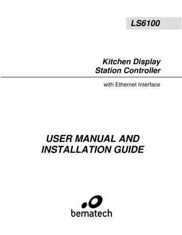
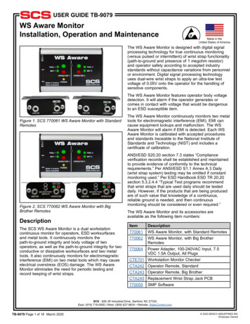
6.1 Markingsping200Sping200Sr7 Equipment Limitations7.1 Installation7.1.1 Modifications and Use Outside of Intended ScopeThis device has been designed and tested to conform to all applicablestandards in the original form and when configured with the componentsshipped with the device. It is not permissible to modify the device, use thedevice for any use outside of the intended scope, or use the device withany antenna other than the one shipped with the device.UAV-1000711-001 Rev EECN 7A994Page 12 31
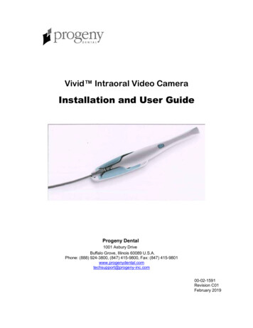
8 Equipment InstallationThis section describes the installation of Ping200Sr and relatedaccessories in the aircraft, including mounting, wiring, and connections.8.1 Unpacking and InspectingCarefully unpack the device and make a visual inspection of the unit forevidence of any damage incurred during shipment. If the unit is damaged,notify the shipping company to file a claim for the damage. To justify yourclaim, save the original shipping container and all packing materials.8.2 MountingThe Ping200Sr is designed to be mounted in any convenient location in thecockpit, the cabin, or an avionics bay.The following installation procedure should be followed, remembering toallow adequate space for installation of cables and connectors. Select a position in the aircraft that is not too close to any highexternal heat source. The Ping200Sr is not a significant heat sourceitself and does not need to be kept away from other devices for thisreason. Avoid sharp bends and placing the cables too near to the aircraftcontrol cables. Secure the transponder to the aircraft via the three (3) mountingholes. It should be mounted on a flat surface.UAV-1000711-001 Rev EECN 7A994Page 13 31
8.3 Connections!Whenever power is supplied to the transponder, a 50ohm loadmust be provided to the SMA connection. You can use thesupplied antenna or a commercially available 50ohm load.Powering the transponder without an attached load will result indamage to the device not covered under warranty.UAV-1000711-001 Rev EECN 7A994Page 14 31
UAV-1000711-001 Rev EECN 7A994Page 15 31
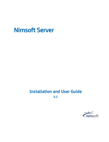
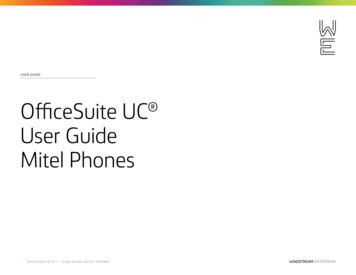
8.4 Wiring DiagramUAV-1000711-001 Rev EECN 7A994Page 16 31
Control 33VPower4COM TXRS-232 OutProgrammable5COM RXRS-232 InProgrammable6RS232GroundMating Connector: Molex 0436450600, Pins: 0462350001Transponder LEDsLEDREDSOLIDFAULTGREENPoweredFLASHINGReply /TransmitReceivingInterrogationUAV-1000711-001 Rev EECN 7A994Page 17 31
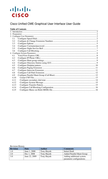
8.5 Cooling RequirementsPing200Sr is designed to meet all applicable TSO requirements withoutforced-air cooling.Attention should, however, be given to the incorporation of coolingprovisions to limit the maximum operating temperature if Ping200Sr isinstalled in close proximity to other Avionics. The reliability of equipmentoperating in close proximity in an avionics bay can be degraded if adequatecooling is not provided.8.6 Antenna InstallationThe following considerations should be taken into account when siting theantenna. The antenna should be mounted in a vertical position when theaircraft is in level flight. Avoid mou
Environmental RTCA/DO-160G RTCA/DO-160G FCC ID 2AFFTP200S 2AFFTP200S FAA Transmit License Manned aircraft. Un-manned operating above 500ft AGL. Manned aircraft. Un-manned operating above 500ft AGL. Software RTCA/DO-178C Level C RTCA/DO-178C Level C Hardware RTCA/DO-254 Level C RTCA/DO-254 Level C Operating Temperature -45 C to 70 C -45 C to 70 C Storage