Transcription
Duct optimization using CFD software ‘ANSYS FluentAdjoint Solver’.Master’s thesis in Automotive EngineeringATHANASIOS TZANAKISDepartment of Applied MechanicsDivision of Vehicle Engineering and Autonomous SystemsCHALMERS UNIVERSITY OF TECHNOLOGYGöteborg, Sweden 2014Master’s thesis 2014:43
MASTER’S THESIS IN AUTOMOTIVE ENGINEERINGDuct optimization using CFD software ‘ANSYS Fluent Adjoint Solver’.ATHANASIOS TZANAKISDepartment of Applied MechanicsDivision of Vehicle Engineering and Autonomous SystemsCHALMERS UNIVERSITY OF TECHNOLOGYGöteborg, Sweden 2014
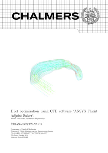
Duct optimization using CFD software ‘ANSYS Fluent Adjoint Solver’.ATHANASIOS TZANAKISc ATHANASIOS TZANAKIS, 2014Master’s thesis 2014:43ISSN 1652-8557Department of Applied MechanicsDivision of Vehicle Engineering and Autonomous SystemsChalmers University of TechnologySE-412 96 GöteborgSwedenTelephone: 46 (0)31-772 1000Cover:Initial and optimized ventilation duct.Chalmers ReproserviceGöteborg, Sweden 2014
Duct optimization using CFD software ‘ANSYS Fluent Adjoint Solver’.Master’s thesis in Automotive EngineeringATHANASIOS TZANAKISDepartment of Applied MechanicsDivision of Vehicle Engineering and Autonomous SystemsChalmers University of TechnologyAbstractThe ordinary duct development procedure in Climate sector at VVC relies on the manual evaluation of theCFD results and the identification of the proper geometry changes in order to optimize the ducts shape. Anewly introduced methodology in automotive sector, the adjoint procedure, could reduce the duration of aduct development process through an automatic iterative procedure. Having computed the flow results, theadjoint obtains the geometry’s sensitivity field which depicts the potential changes in the domain with respectto the cost function. Then a morphing tool utilizes that data and properly modifies the geometry. The currentthesis is focused on experiencing and demonstrating the merits of the adjoint solver aiming to minimize thecost function, the pressure drop, over a duct domain.The discrete adjoint method was applied to different geometries from the Climate sector examining theprerequisites for extended adjoint use. Through those geometries both the adjoint solver and the morphing toollimitations were discovered. The limitations are mostly related to the mesh, the adjoint discretization schemeas well as the boundary constraints. During the thesis, the limitations were identified and properly examined,proposing solutions. An adequate adjoint solution was obtained when using a coarse Polyhedral mesh withcell skewness around 0.8, a low discretization scheme and a simplified geometry. Even if some compromiseswere required in whole procedure, the adjoint has managed to handle all the given geometries. Moreover, newoptimized domains with respect to the cost function, the pressure drop minimization,were developed.The result of the thesis was a guide of how to overcome adjoint constraints as well as an analytical illustrationof the adjoint results. In some cases, the pressure drop was minimized by 60% resulting in a smooth pressuredistribution over the given domain. However, a compromise in the morphing tool leaves room for improvementon the suggested methodology.Keywords: Adjoint, Optimization, Duct, Pressure drop, Methodologyi
AcknowledgementsThis project is carried out in Climate sector at Volvo Car Corporation in collaboration with Department ofApplied Mechanics at Chalmers University of Technology, Sweden.During my thesis at Volvo Car Corporation I was able to develop my CFD skills and perform in real workingenvironment.I would like to thank my supervisor at Volvo Car Corporation, Frida Nordin and my academicalsupervisor at Chalmerls University of Technology, Professor Lennart Löfdag for great support. I would like alsoto thank the other employees at the CFD core group for the support and great time.ii
ContentsAbstractiAcknowledgementsiContentsiii1 Introduction1.1 Purpose . . . . . . . . . . . . . . . . . . . . . . . . . . . . . . . . . . . . . . . . . . . . . . . . . . .1.2 Background . . . . . . . . . . . . . . . . . . . . . . . . . . . . . . . . . . . . . . . . . . . . . . . . .1222 Theory2.1 The governing equations . . .2.2 Wall function . . . . . . . . .2.3 Optimization Methods . . . .2.4 The discrete adjoint approach2.5 Mesh morphing . . . . . . . .3344563 Method3.1 The general method . . . . . . . . . .3.2 Setting up the simulation . . . . . . .3.3 Adjoint solution controls . . . . . . . .3.3.1 Courant Number . . . . . . . . . . .3.3.2 The artificial compressibility method3.3.3 Flow rate courant scaling . . . . . .3.3.4 Under relaxation factor . . . . . . .3.3.5 Algebraic multigrid . . . . . . . . .3.4 Stabilized Scheme . . . . . . . . . . .3.4.1 Modal Stabilization Scheme . . . . .3.4.2 Spatial Stabilization Scheme . . . .3.5 Mesh Morphing . . . . . . . . . . . . .3.6 Given geometries . . . . . . . . . . . .8899101010101010101112134 Methodology results4.1 Mesh . . . . . . . . . . . . . .4.1.1 Harpoon as a mesher . . .4.1.2 ANSA as a mesher . . . . .4.1.3 Polyhedral mesh . . . . . .4.2 Adjoint discretization scheme4.3 Domain partitioning . . . . .4.4 Domain Morphing . . . . . .4.5 Stabilization scheme . . . . .4.6 Under relaxation factor . . .4.7 Boundary modifications . . .15151515171819212223245 Adjoint results5.1 Contour of normal optimal displacement . . . . . . . . . . . . . . . . . . . . . . . . . . . . . . . . .5.2 Pressure drop . . . . . . . . . . . . . . . . . . . . . . . . . . . . . . . . . . . . . . . . . . . . . . . .5.3 Flow visualization . . . . . . . . . . . . . . . . . . . . . . . . . . . . . . . . . . . . . . . . . . . . .262628306 Discussion327 Future work33References34.iii
iv
1IntroductionFinding the optimum solution in a given flow domain relies on both accurate flow prediction through Computational Fluid Dynamics (CFD) simulations and also on design methods, appropriate to generate new optimumconfigurations.Many optimization methods already exist, yet their limitations with respect to required time as well astheir efficiency of handling many design variables, define the proper method for each case. The gradient basedmethod is the most well known method that can cope with many design variables. The gradient of the costfunction is the key factor for the further shape optimization [9].Numerical optimization methods in combination with flow simulations could be used to face the designproblem.These methods require the gradient of the objective function with respect to modifications in thedesirable variable in order to define the magnitude of domain change. Finite difference method is the simplestway to calculate those gradients. However, it requires an iterative procedure as the gradient components areobtained by independently changing each design variable with finite step ,calculating the desired objectivefunction using CFD analysis and estimating the ratio of differences. In each iteration the local minimum ormaximum of the objective function is calculated and the process is repeated until the gradient tends to zero [9].So, in case of perturbing N points on the given surface, N flow simulations are required to obtain the data setwhich lead to optimum solution [2] .Consequently,the finite difference method requires high computational time as the design variables N areincreasing. In contrast, adjoint method is able to obtain design sensitivities of a function with respect to manydesign variables in a single adjoint computation. This implies that the computational cost for the gradientcalculation is equal to that for solving the flow equations. The adjoint is implemented into a finite volume solverusing either continuous or discrete approach [2]. In the current study, ANSYS FLUENT applies the discreteapproach due to its ability to provide more robust sensitivity information in cases with complex geometryconfigurations [2].A converged adjoint solution provides the domain morphing sensitivities, identifying the areaswhere the domain mesh should be modified.The ANSYS FLUENT mesh adaption method is based on gradientalgorithm , adjusting the system in a way that maximizes the effect of change. For instance, in areas wheresensitivity is relatively high, small modification in shape will lead to high impact on the objective function.Additionally, a smooth and equally distributed deformation is applied on the surface with respect to the costfunction[2].The adjoint method has been used as an optimization tool in the aerodynamics field since 1984. Adjointsolver has been introduced by Pironneau and firstly applied to shape design for Elliptic Systems [8] .In thecurrent study, adjoint method is focused on internal flows and having as objective function the pressure dropminimization. For that purpose, a variety of parameters which could influence both the adjoint solution andthe morphing feature have been investigated. The mesh type and skewness as well as the adjoint discretizationscheme are few of the parameters that sticks out as important factors for establishing a robust methodology.Moreover, the results of four different cases which illustrate different topology limitations as well as morphingconstraints,are presented in the report .Firstly, a geometry of a front floor duct was given which was analyzed in scope of compatible mesh generatorwith adjoint solver in terms of mesh quality. In that case, the entire geometry was morphed without limitationsaiming to obtain an overall knowledge around both adjoint and morphing tool. Later on, rear floor duct wasexamined, where issues related with type of mesh and morphing feature were observed. Once all issues wereaddressed, adjoint methodology was applied in more complex and demanding geometries of B-pillar duct andfront ventilation system. However, some new adjoint constraints came up ,yet they were worked out throughcompromises in morphed areas.1
1.1PurposeThe current study will evaluate the possibilities for VCC to use ‘ANSYS Fluent Adjoint Solver’ when developingducts to the car ventilation system. This involves investigating prerequisites and restrictions with the softwareas well as robustness and ease of use. The main delivery from the thesis will be a verdict on the possibility ofusing the Adjoint Solver for a duct optimization and also a best practice guideline of how to use it.1.2BackgroundThe shape of a duct in a car climate system is rarely designed from a fluid dynamic point of view. Thecompetition of space is intense when developing a new car and the ducts are often squeezed in between othercomponents. As a result, the duct shape can be very complex and finding optimal shape improvements is notintuitive. In order to speed up the development process of an air ventilation duct and also find the best possiblesolution in terms of fluid dynamic performance, we are interested in evaluating ‘ANSYS Fluent Adjoint Solver’.After a CFD solution is computed, ‘ANSYS Fluent Adjoint Solver’ identifies which regions of a shape are mostsensitive to changes with respect to a defined quantity of interest. That data can then be used as input formorphing of the volume or surface mesh and the shape can be optimized in terms of the quantity of interest.2
2TheoryIn the current chapter the flow field governing equations and their discretized form, are presented. Moreover,the gradient based optimization methods as well as the advantages of adjoint approach, are briefly discussed.As the discrete adjoint approach is applied in that study, a further analysis of this approach takes place. Atthe end of the chapter the basic theory of ANSYS mesh morphing method is presented. This method is appliedafter obtaining the surface sensitivity field through the adjoint solver.2.1The governing equationsThe numerical analysis of the current duct flow study relies on assumption of incompressible and isothermalflow. The incompressible continuity equation is described by, ui 0 xi(2.1)since the flow field is described by Newtonian fluid the Navier - Stokes equations can be written in the followingform for the development of the finite volume method,ρ ui ui p τ ij ρuj t xj xi xj(2.2)where τ ij represents the viscous stress components.τ ij µ( ui uj ) xj xi(2.3)The turbulent flow calculation was numerically analyzed by Reynolds-averaged Navier-Stokes equations. Thismethod is focused on the mean flow, obtaining a time averaged solution to the Navier Stokes equation. Inorder to achieve that, the instantaneous part ϕi (x, t) is divided into mean,Φi (x) and fluctuating ϕ0i (x, t). TheReynolds decomposition is applied into instantaneous velocity and pressure, respectively.ui (x, t) Ui (x) u0i (x, t)(2.4)pi (x, t) Pi (x) p0i (x, t)(2.5)Inserting equation 2.4 and 2.5 into 2.2, as well as considering the time average of the fluctuation to be zeroϕ0i (x, t) ,the following equation is obtained,ρ Ui 0 xi(2.6) Ui Ui P τ ij ρUj t xj xi xj(2.7)where tota
Duct optimization using CFD software ‘ANSYS Fluent Adjoint Solver’. ATHANASIOS TZANAKIS c ATHANASIOS TZANAKIS, 2014 Master’s thesis 2014:43 ISSN 1652-8557 Department of Applied Mechanics Division of Vehicle Engineering and Autonomous Systems Chalmers University of Technology SE-412 96 G oteborg Sweden Telephone: 46 (0)31-772 1000 Cover: