Transcription
Tutorial Guide toAutoCAD 2016 2D Drawing, 3D ModelingShawna LockhartSDCP U B L I C AT I O N SBetter Textbooks. Lower Prices.www.SDCpublications.comFor Microsoft Windows
Visit the following websites to learn more about this book:Powered by TCPDF (www.tcpdf.org)
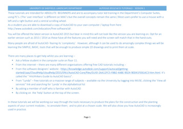
INTRODUCTION 59Basic Construction TechniquesIntroductionYou usually create drawings by combining and modifying several different basic primitive shapes, such as lines, circles, and arcs, to create morecomplex shapes. This tutorial will help you learn how to draw shapes.Keep in mind that one of the advantages of using CAD over drawingon paper is that you are creating an accurate model of the drawinggeometry. In Tutorial 3, you will learn to list information from the drawing database. Information extracted from the drawing is accurate only ifyou create the drawing accurately in the first place.2ObjectivesWhen you have completed this tutorial, youwill be able to1. Open existingdrawings.2. Work with new andexisting layers.StartingBefore you begin, launch AutoCAD 2016.Opening an Existing DrawingThis tutorial shows you how to add arcs and circles to the subdivisiondrawing provided with the datafiles that came with this guide. In Tutorial 3 you will finish the subdivision drawing so that the final drawingwill look like Figure 2.1.3. Draw, using the Arcand Circle commands.4. Set and use runningObject snaps.5. Change the display,using Zoom and Pan.6. Use Dynamic View.7. Draw ellipses.A SUBDIVISION LOCATED IN THE NE1/4 OF THE NE 1/4 OF SEC. 14,T.1S, R.5E, M.P.MA 15’ UTILITY EASEMENT ISRESERVED ALONG ALL EXTERIORLOT LINES.BRONWYNECSNROADGAPONDET2RRADY ROTAS110CIRCLE3456789Wannabe Heights EstatesFigure 2.1To open an existing drawing, use the Application icon, Open selectionor click the button that looks like an open folder from the Quick Accesstoolbar.Click: Open buttonThe Select File dialog box appears on your screen. Use the centerpor tion, which shows the default directory and drive, to select the location where your datafiles have been stored. You should have alreadycreated a directory called c:\datafile2016, and copied all the datafiles forthis book into it. If you have not done so, you may want to review theGetting Started chapters. If the correct directory is not showing in theTip: It is easy to download thedatafiles. Use your browser tonavigate to www.sdcpublications.com/Authors/ShawnaLockhart. From there select thetext you are using. Find andclick the Download button onthe page for your text.
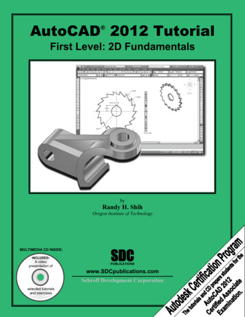
60 Tutorial 2 BASIC CONSTRUCTION TECHNIQUESLook In box, use the Up One Level icon or expand the choices by clicking on the downward arrow for the Look In box. Use the scroll bars ifnecessary to scroll down the list of directories and open the appropriateone so the files appear in the dialog box as in Figure 2.2. Scroll downthe list of files until you see the file named subdivis.dwg. When youselect a file, a preview of the file appears in the box to the right. (Olderfiles may not show a preview.)Tip: Use the buttons at the leftof the dialog box to show theHistory (recently used files), MyDocuments folder contents, orFavorites you have added. Toadd a favorite, find the folderand then right-click the Favorites button. Pick Add CurrentFolder from the pop-up menuthat appears. To add a folderas a button, pick Tools, AddCurrent Folder to Places.You can also use Autodesk 360to display documents you havestored on a remote internetserver sometimes called “thecloud”. This allows you to viewyour files from anyplace youcan connect to the internet. Youcan also browse your computer’s desktop and Autodesk’sBuzzsaw area from these sidebar icons.Figure 2.2Menu choices at the top right of the Select File dialog box let you selectdifferent views to be displayed in the file list and other useful tools, suchas a Find selection to search for files.Click: Tools, FindType: subdivis (in the Named area)Click: Find Now button (from upper right of dialog box)The Find dialog box displays the location for the file named Subdivis.dwg, as shown in Figure 2.3. You can type in a portion of the name tomatch if you cannot remember the entire name or click the Date Modified tab if you want to search by date and time the file was created.Figure 2.3
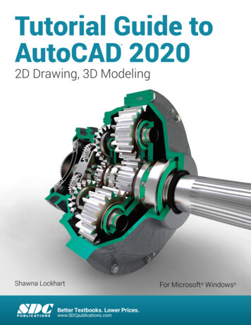
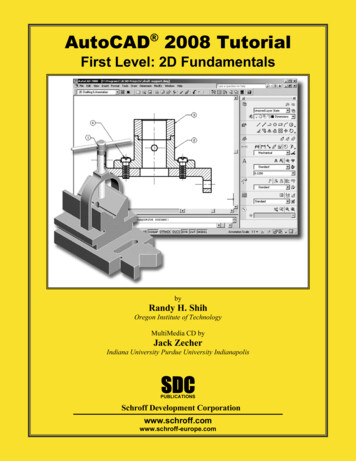
SAVING AS A NEW FILE 61Double-click: Subdivis.dwg ( to select it from the list at the bottom)You return to the Select File dialog box.Click: OpenDouble-click: in the center of the screen to zoom to the drawingextentsWhen you have opened the file, it appears on your screen, as shown inFigure 2.4. Note that it opens with its own defaults for Grid, Snap, andother features. These settings are saved in the drawing file. When youopen a drawing, its own settings are used.Figure 2.4Saving as a New FileThe Save As command allows you to save your drawing to a new filename and/or different drive or directory. You can select this commandfrom the Application icon or from the Quick Access toolbar.Don’t use the Save command, because that will save your changes intothe original datafile.Click: Save As buttonThe Save Drawing As dialog box appears on your screen similarto Figure 2.5.
62 Tutorial 2 BASIC CONSTRUCTION TECHNIQUESTip: Notice that if you have setup an account, you can use theA360 selection to save yourfiles to storage in the “cloud”.Figure 2.5Warning: If you save a file withthe same name as one alreadyin the directory, you will see amessage the file “already exists. Do you want to replace it?”Choose No unless you want toreplace the file.In this case, the new file name is the same as the previous file name, butthe directory is different. This creates a new copy of drawing subdivis.dwg saved in the directory c:\work.On your own, select the drive and directory c:\work and specify the name for yourdrawing, subdivis.dwg.The original file c:\datafile2016\subdivis.dwg remains unchanged onyour drive. When you use the Save As command and specify a new filename, the software sets the newly saved file as current.Using LayersYou can organize drawing information on different layers. Think of alayer as a transparent drawing sheet that you place over the drawingand that you can remove at will. The coordinate system remains thesame from one layer to another, so graphical objects on separate layersremain aligned. You can create a virtually unlimited number of layerswithin the same drawing. The Layer command allows control of thecolor and linetype associated with a given layer. Using layers allows youto overlay a base drawing with several different levels of detail (such aswiring or plumbing schematics over the base plan for a building).By using layers, you can also control which portions of a drawing areplotted, or remove dimensions or text from a drawing to make it easierto add or change objects. You can also lock layers, making them inaccessible but still visible on the screen. You can’t change anything on alocked layer until you unlock it.Current LayerThe current layer is the layer you are working on. Any new objects youdraw are added to the current layer. The default current layer is layer 0.If you do not create and use other layers, your drawing will be createdon layer 0. You used this layer when drawing the plot plan in Tutorial 1.Layer 0 is a special layer provided in the AutoCAD program.
CONTROLLING LAYERS 63You cannot rename or delete layer 0 from the list of layers. Layer 0has special properties when used with the Block and Insert commands,which are covered in Tutorial 10.Layer POINTS is the current layer in mysubdivis.dwg. There can beonly one current layer at a time. The name of the current layer appearson the Layer toolbar.Controlling LayersThe Layer Control feature on the Layers panel on the Home tab of theribbon is an easy way to control the visibility of existing layers in yourdrawing. You will learn more about creating and using layers in thistutorial. For now, you will use layers that have already been created foryou.Click: on layer name POINTS from the Layers panelThe list of available layers pulls down, as shown in Figure 2.6. Noticethe special layer 0 displayed near the top of the list.Figure 2.6Click: on the layer name CENTERLINE from the Layer Control listIt becomes the current layer shown on the toolbar. Any new objects willbe created on this layer until you select a different current layer. TheLayer Control now should look like Figure 2.7, showing the layer nameCENTERLINE.Figure 2.7Use the Line command you learned in Tutorial 1 to draw a line off to the side ofthe subdivision drawing.Note that it is green and has a centerline linetype (long dash, shortdash, long dash). The line you drew is on Layer CENTERLINE.Erase or Undo the line on your own.
64 Tutorial 2 BASIC CONSTRUCTION TECHNIQUESControlling ColorsEach layer has a color associated with it. Using different colors for different layers helps you visually distinguish different information in thedrawing. An object’s color also may control appearance during printing.There are two different ways of selecting the color for objects onyour screen. The best way is usually to set the layer color and drawthe objects on the appropriate layer. This method keeps your drawingorganized. The other method is to use the Color Control feature on theProperties panel. To select the Color Control pull-down feature,Click: ByLayer from the Properties panel to pull down the ColorControlTip: If your panelsare minimized, youmay need to click toexpand the options.Click to expandcolor choicesFigure 2.8Note that the standard colors (yellow, red, green, blue, etc.) are shown.You can also choose More Colors to view the full color palette.Click: More ColorsThe Select Color dialog box shown in Figure 2.9 appears on yourscreen, giving you a full range of colors from which to choose.Tip: On a black background,color 7 used for layer 0 appearsas white; on a white background it appears black.Figure 2.9The three tabs of the Select Color dialog box allow you to chooseamong different methods to determine the color for your drawingentities. The True Color tab allows you to set color to either RGB, whichstands for Red, Green, Blue, the primary colors of light, or HSL, whichstands for the Hue, Saturation, and Luminance of the color. The Color
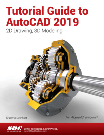
LAYER VISIBILITY 65Books tab lets you select from among different standard ink manufacturer’s predefined colors so that you can match print colors very closelyto the colors you choose on your screen. In this text you will use IndexColor (AutoCAD Color Index) as the method for selecting color.Make sure the Index Color tab is selected.The default option for the Color (and also for the Linetype) commandis BYLAYER. It’s the best selection because, when you draw a line,the color and linetype will be those of the current layer. Otherwise, thecolor in your drawing can become very confusing. You will click Cancelto exit the Select Color dialog box without making any changes. Thecolors for your new objects will continue to be determined by the layeron which they are created. Layers can have associated linetypes, as wellas colors, as Layer CENTERLINE does.Click: CancelLayer VisibilityOne of the advantages of using layers in the drawing is that you canchoose not to display selected layers. That way, if you want to createprojection lines or even notes about the drawing, you can draw them ona layer that you will later turn off, so that it isn’t displayed or printed.Or you may want to create a complex drawing with many layers, suchas a building plan that contains the electrical plan on one layer and themechanical plan on another, along with separate layers for the walls,windows, and so on. You can store all the information in a single drawing, and then plot different combinations of layers to create the electrical layout, first-floor plan, and any other combination you want.Next you will use the Layer Control to lock, freeze, and turn off some ofthe layers in this drawing.Click: on CENTERLINE to show the list of layersThe list of layers pulls down. Refer to Figure 2.10 as you make thefollowing selections.Click: the On/Off icon, which looks like a lightbulb, to the left ofLayer EXISTING ROADClick: any blank area of the screen away from the Layer list toreturn to the drawingNote that the blue roadway lines have been turned off so that theyno longer appear. Invisible (off) layers are not printed or plotted, butobjects on these layers are still part of the drawing.Figure 2.10Layer Control
66 Tutorial 2 BASIC CONSTRUCTION TECHNIQUESFreezing LayersFreezing a layer is similar to turning it off. You use the freeze option notonly to make the layer disappear from the display, but also to cause it tobe skipped when the drawing is regenerated. This feature can noticeablyimprove the speed with which the software regenerates a large drawing.You should not freeze the current layer because that would create asituation where you would be drawing objects that you couldn’t see onthe screen. The icon for freezing and thawing layers looks like a snowflake when frozen and a shining sun when thawed.Click: to expand the Layer Control listClick: the Freeze/Thaw icon to the left of Layer TEXTClick: any blank area in the graphics window to return to thedrawingLayer TEXT is still on, but it is frozen and therefore invisible. A layercan both be turned off and frozen; the effect is similar. You shouldeither freeze a layer or turn it off, but there is no point in doing both.Your screen should now be similar to Figure 2.11.Figure 2.11Locking LayersYou can see a locked layer on the screen, and you can add new objectsto it. However, you can’t make changes to the new or old objects onthat layer. This is useful when you need the layer for reference but donot want to change it. For example, you might want to move severalitems so that they line up with an object on the locked layer but preventanything on the locked layer from moving. You will lock layer POINTSso that you cannot accidentally change the points already on the layer.Click: t
Layer 0 is a special layer provided in the AutoCAD program. Tip: Notice that if you have set up an account, you can use the A360 selection to save your files to storage in the “cloud”. Warning: If you save a file with the same name as one already in the directory, you will see a message the file “already ex-ists. Do you want to replace it?”