Transcription
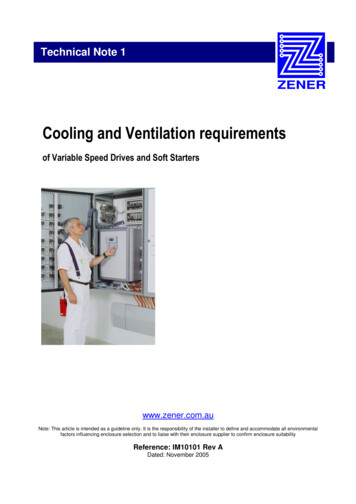
Technical Note 1Cooling and Ventilation requirementsof Variable Speed Drives and Soft Starterswww.zener.com.auNote: This article is intended as a guideline only. It is the responsibility of the installer to define and accommodate all environmentalfactors influencing enclosure selection and to liaise with their enclosure supplier to confirm enclosure suitabilityReference: IM10101 Rev ADated: November 2005
Section 1.0 - IntroductionThis document is intended to be a guide for the installation of Variable Speed Drives and Soft Starters toensure adequate cooling or ventilation is provided. All power electronic equipment will dissipate heat whichmust be removed to prevent overheating of the semiconductor devices or other components. The installationand environmental factors must be considered with all external sources of heat removed or minimised. Animportant consideration is the effects of direct sunlight, in which all precautions should be taken to removethe effects by providing adequate shelter.The scope of this technical note is to provide guidance to calculate ventilation / cooling requirements, but thecalculations make no consideration for external factors such as direct sunlight, other heat sources etc.Dated: November 2005Page 1IM10101 Rev A
Section 2.0 – Heat DissipationAll Power electronic equipment generates heat during operation which must be removed to maintain theequipment operating temperature below its rated value. The first step is to calculate how much heat theequipment generates. This is dependant upon the type of equipment and how it is configured and operated.2.1 Soft StartersSoft Starters use power devices in the form of thyristors or SCR’s which generally have an efficiency of about99%. Soft Starters may be configured to operate in a continuous or bypass mode. Continuous is when theSCR’s are dissipating heat whist ever the motor is running. In bypass configuration the SCR’s are onlyoperating during starting and stopping, all other times the SCR’s are bypassed using a bypass contactor.When the SCR’s are bypassed they dissipate no heat, therefore minimising the ventilation required. Thereduced heat dissipation is a common deciding factor for bypass configuration.2.1.1 Calculating the heat dissipationThe heat produced by the soft starter can be calculated from the motor full load current rating according tothe following formula:1.Continuous DutyPLOSS FLC x 4.52.Bypass DutyPLOSS (FLC x SC x 4.5 x t x N) / 3600PLOSSPower dissipated by soft starter, in W (Watts)FLCMotor full load current, in A (Amps)tStarting time, in secondsNNumber of starts per hour.SCAverage starting current expressed as per unit of FLCExample:What is the expected heat dissipation of a 22kW motor of 42A FLC operating at 5 starts per hour at 15seconds per start at a start overload 300% FLC.Continuous DutyPLOSS 42 x 4.5 189 WBypass DutyPLOSS (42 x 3 x 4.5 x 15 x 5) / 3600 12 WDated: November 2005Page 2IM10101 Rev A
Section 2.0 – Heat Dissipation2.2 Variable Speed DrivesThe thermal losses of the Variable Speed Drive may for all practical purposes be assumed to be about 3%.Smaller Variable Speed Drives are approximately 4% and as the drive increases in size the percentage ofthermal losses decreases to about 3%.Example:What is the estimated heat generated by a 40A VSD controlling a 22kW motor at full load?PLOSS 22kW x 0.03 0.66kW 660W2.3 Auxiliary EquipmentWhere additional equipment is mounted in the same enclosure as the soft starter or Variable Speed Drive,any heat generated by such auxiliary equipment must be added to the total heat generated. Equipmentsuppliers can provide details of the heat generated by their equipment.2.4 Installation alternativesVariable Speed Drives and Soft Starters are available in different types of enclosures like most electricalequipment to suit the environment which they are to be installed. The type of enclosure supplied is based onthe level of protection offered against water and objects, known as an IP rating. If the protection offered is notadequate for the environment to be installed then the alternatives need to be investigated.These alternatives may include; Use a product with higher protection rating.Zener Drives are available in IP30, IP66 and also Stainless Steel IP66 which means they maybe installed without further protection. Relocate to alternative location.This is sometimes necessary when the environment may be extremely corrosive or flammable. Install equipment in an enclosure with a higher protection rating.When equipment that generates heat is installed into another enclosure the heat must bedissipated. If this heat is not removed the heat inside will build up to a level which will affect thereliable operation of the equipment, reduce the life expectancy of the product or cause failure toother equipment. If choosing to ventilate an enclosure this may reduce the protection rating to anunacceptable level.Dated: November 2005Page 3IM10101 Rev A
Section 3 – Enclosure Dissipation / Ventilation3.1 Dissipation of Heat Generated inside an EnclosureThe heat generated within an enclosure may be dissipated by: The enclosure wall surface area (ie. non ventilated) Forced air ventilation Heat exchanger or water cooling (not dealt with in this article)The dimensions of the enclosure, how it is mounted and the outside ambient temperature will then define theamount of heat that can be dissipated through the exposed surfaces of the enclosure. Where the surfacearea of the enclosure is insufficient to dissipate the heat generated inside the enclosure, the remaining heatmay be removed by forced ventilation.3.2 Non Ventilated EnclosureNon ventilated enclosures rely on the heat being dissipated through the walls of the enclosure. The betterheat conduction of the enclosure the more heat dissipated. For this reason metal enclosures are far better atdissipating heat than plastic enclosures.The power that can be dissipated in a given exposed surface area is;PESA k x S x TPESAPower dissipated from within the enclosure via exposed surface area in W (Watts)kHeat transfer coefficient [sheet metal 5.5W/m K, plastic 3.5W/m K ]SCorrected enclosure surface area of the enclosure, in m in accordance with IEC890.222Details on calculating the value of S are provide in section 3.2.1 TTemperature differential (inside enclosure - outside ambient), in CExample:A 110kW 187A motor is started using a soft starter where the starting time is 30 seconds with overloadcurrent of 450% and 3 starts per hour. The soft starter is rated for 45 C ambient and the outside ambient isworst case 35 C. Select a suitable enclosure size for bypass operation. Installed in a single enclosuremounted against a wall: dimensions 1000mm(H) 800mm(W) 320mm(D)Bypass DutyPLOSS (187 x 4.5 x 4.5 x 30 x 3) / 3600 95 W(For purpose of this example, the only auxiliary equipment losses (line contactor and bypass contactor) areconsidered negligible and hence ignored.)Effective enclosure area:2S 1.4 x 0.8 x (1 0.32) 1.8 x 0.32 x 1 2mPESA 5.5 x 2 x 10 110 WTherefore, PESA PLOSS so that enclosure is suitable without any ventilationDated: November 2005Page 4IM10101 Rev A
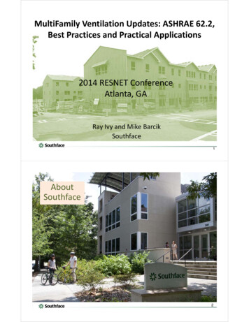
Section 3 – Enclosure Dissipation / Ventilation3.2.1 Calculation of SThe value of S is the corrected enclosure surface area based on the method of installation in accordance withIEC60-890. S is calculated by using the appropriate formula below.Enclosure PositionLocation (IEC60-890)Formula for calculating SAccessible on all sidesS 1.8 x H x (W D) 1.4 x W x DPlaced against a wallS 1.4 x W x (H D) 1.8 x D x HEnd of a row of enclosuresS 1.4 x D x (H W) 1.8 x W x HEnd of a row of enclosures with theback against the wallS 1.4 x H x (W D) 1.4 x W x DIntermediate in a row of enclosuresS 1.8 x W x H 1.4 x W x D D x HIntermediate in a row of enclosureswith the back against the wallS 1.4 x W x (H D) D x HIntermediate in a row of enclosuresback against the wall with top part coveredS 1.4 x W x H 0.7 x W x D D x HDated: November 2005Page 5IM10101 Rev A
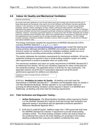
Section 3 – Enclosure Dissipation / Ventilation3.3 Ventilated EnclosureWith ventilated enclosure the heat is dissipated by forcing ambient air in or out of the enclosure. Theobjective is to circulate the air through the enclosure, so it is not critical whether the fan creates a pressure orvacuum in the enclosure (ie blows in or out). Generally ambient air is drawn in at the bottom of the cabinetthrough and discharged through a ventilation opening at the top. The outlet should be placed above thehighest mounted drive or starter.Filters installed on Fan units provide a better protection rating (normally max IP54) but impede the flow of air.It is important to check the manufacturer’s specifications when a filter is fitted. Additionally, if the filter collectsany dust the airflow will be reduced significantly and needs to be considered in your selection decision anddesign.The volume of air required can be estimated using the formula.V (3.1 x PEXHAUST) / T3VVolume of air flow required, in m /hrPEXHAUSTPower exhausted from within the enclosure, in W (Watts) TTemperature differential (inside enclosure - outside ambient), in CExample:Three (3) 4kW Variable Speed Drives are to be installed in an enclosure. Calculations based on operating atfull capacity of the drive. Assuming a power loss of 3.5% and a temperature differential of 10 C.PLOSS (4kW x 0.035) x 3(ie. 3 drives) 420WattsVolume (3.1 x PEXHAUST) / T (3.1 x 420) / 103 130 m /hr3Therefore, a fan or combination of fans would be required to provide 130m /hr of airflow.Dated: November 2005Page 6IM10101 Rev A
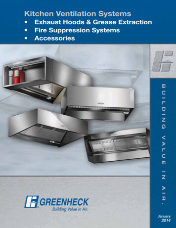
Section 4 – Other Considerations4.1 Equipment SpacingTo adequately exhaust heat generated, certain minimum clearances must be maintained around the VSDand soft starter. Please refer to the product installation manual for details.4.2 Equipment / stirring FansStirring fans can distribute the heat evenly throughout the enclosure to avoid hot spots. Fans can becontrolled to run for a given time at starting or temperature controlled to extend fan life and reduce audiblenoise.4.3 Forced VentilationWhere ventilation is used to exhaust heat, care should be taken with regard to IP rating of the enclosure.Furthermore the size of the air intake should be at least the size of the exit and if more than one fan is usedthen the fans should be the same. Remember where filters are used you must take into account pressuredrops across the filters. Filters should be inspected regularly for blockage as part of the maintenanceschedule to ensure free air flow and correct operation. Force ventilation may also be temperature controlledto minimize running time and increase the life expectancy of the fans.4.4 Equipment De-ratingThe components of electronic equipment are designed to operate under full load at a particular maximumtemperature. By reducing the load, the internal operating temperature will be reduced allowing the equipmentto operate in a higher ambient temperature. Please refer to the instruction manual or contact your local Zenerrepresentative for manufacture de-rating.4.5 Solar HeatingExposure of the enclosure to the sunlight (direct or reflected) will result in solar heating. Proper use of ashelter will reduce such heating; and enclosure material and paint colours have different absorptionproperties of solar energy. Variable Speed Drives and Soft Starters should not be mounted in direct sunlightor on hot surfaces.4.6 EnvironmentThe environment of an installation determines the type of enclosure to be used. Where dust and water (ormoisture) are present one may consider using an IP66 enclosure which would then rely entirely on radiatedheat loss for cooling or a heat exchanger will be needed. For aggressive environments one may use astainless steel or plastic enclosure. If a fan or fan/filter is installed the IP66 rating will be degraded.The MSC-3 provides an easy solution with the IP66 or the stainless steel IP66 enclosure option. All the heatloss is taken care of and can be directly mounted on a wall (see instruction manual for further information).The VSD has an integral dual compartment heat exchanger where the VSD electronic components arehoused in a totally enclosed compartment, and the heat from the VSD is ventilated in a separatecompartment housing the heatsink and ventilation fan (no filters are used). The VSD can be field mountedcloser to the motor thus reducing costs of screened cable.Dated: November 2005Page 7IM10101 Rev A
3.2.1 Calculation of S The value of S is the corrected enclosure surface area based on the method of installation in accordance with IEC60-890. S is calculated by using the appropriate formula below. Enclosure Position Location (IEC60-890) Formula for calculating S Accessible on all sides S 1.8 x H x (W D) 1.4 x W x D