Transcription
Fundamentals of HVAC Control Systems
This page intentionally left blank
Fundamentals of HVAC ControlSystemsThe reading text for this course was originally written by Steven T. Taylor, P.E.It was then partially revised by Ross Montgomery P.E.before being edited and partly rewritten by Robert McDowall P.Eng.
#2009 American Society of Heating, Refrigerating and Air-Conditioning Engineers, Inc.1791 Tullie Circle, NEAtlanta, GA 30329www.ashrae.orgElsevier Science is an imprint of Elsevier30 Corporate Drive, Suite 400Burlington, MA 01803, USAAll rights reserved.ISBN 978-0-08-055234-7Printed in the United States of America.ASHRAE has compiled this publication with care, but ASHRAE has not investigated, andASHRAE expressly disclaims any duty to investigate, any product, service, process, procedure,design, or the like that may be described herein. The appearance of any technical data or editorialmaterial in this publication does not constitute endorsement, warranty, or guaranty by ASHRAEof any product, service, process, procedure, design, or the like. ASHRAE does not warrant that theinformation in the publication is free of errors, and ASHRAE does not necessarily agree with anystatement or opinion in this publication. The entire risk of the use of any information in thispublication is assumed by the user.No part of this book may be reproduced without permission in writing from ASHRAE, exceptby a reviewer who may quote brief passages or reproduce illustrations in a review withappropriate credit; nor may any part of this book be reproduced, stored in a retrieval system,or transmitted in any way or by any means—electronic, photocopying, recording, orother—without permission in writing from ASHRAE.Library of Congress Cataloging-in-Publication DataApplication submittedWorking together to growlibraries in developing countrieswww.elsevier.com www.bookaid.org www.sabre.org
ContentsForeword1 Introduction to HVAC Control Systems1.11.21.31.41.51.61.71.8TheWhy Do We Need Controls?A Brief History of ControlsControl LoopsControl ModesTwo-position ControlFloating ControlModulating ControlPulse-width Modulating, and Time-proportioning ControlGains and Loop TuningControl Actions and Normal PositionControl Range, and SequencingControls Documentation, Maintenance, and OperationsNext Step2 Basics of Electricity2.12.22.32.42.52.62.7TheSimple Circuits and Ohm’s LawAC CircuitsTransformers and Power ServicesRelaysMotors and Motor StartersVariable Speed DrivesRelay Logic and Ladder DiagramsNext Step3 Control Valves and DampersIntroduction3.1 Two-way Control ValvesStyles and Principles of Operation3.2 Three-way Control Valves3.3 Selecting and Sizing ValvesFlow Characteristic SelectionClose-off Pressure3.4 Control DampersStyles and Principles of Operation3.5 Selecting and Sizing 6262636373778285888891
viContentsTwo-position DutyCapacity Control DutyMixing DutyThe Next Step4 Sensors and Auxiliary Devices4.14.24.34.44.54.64.7TheIntroduction to TermsAccuracyRangeReliabilityRepeatability, PrecisionTransmitterTemperature SensorsBimetalFluid ExpansionElectrical, Self-poweredElectrical ResistanceHumidity and the Psychrometric ChartIndoor Air is a Mixture of Dry Air and Water VaporRelative HumidityMoisture SensorsRelative Humidity SensorsPressure SensorsFlow Sensors and MetersAuxiliary DevicesNext Step5 Self- and System-powered Controls5.15.2Principles of Operation – Self-powered ControlsExamples of Self-Powered ControlsThermopile ControlsHot Water Control ValveSelf-powered VAV Diffuser5.3 System-powered ControlsSystem-powered Air ValvesSystem-powered Water System ValvesThe Next Step6 Electric Controls6.16.26.36.46.56.6TheSensorsControllers, Two-positionControllers, ModulatingExample ApplicationActuatorsAuxiliary DevicesNext 167168169169171173176179180181
Contents7 Pneumatic Controls7.17.27.37.47.57.67.7ThePrinciples of OperationSensorsControllersActuatorsAuxiliary DevicesCompressed Air SupplyExample ApplicationsNext Step8 Analog Electronic 198200206207Principles of OperationSensorsControllersActuatorsAuxiliary DevicesExample ApplicationsNext Step2072082082132142142179 Control Diagrams and Sequences2189.19.29.39.49.5Control Systems Design CriteriaControl Systems Design ProcessControl Diagrams and SymbolsControl SequencesExample ApplicationsTypical Single-Zone SystemTypical Constant Air Volume System with Faceand Bypass DampersTypical Constant Air Volume System with Multiple Zonesor ReheatTypical Variable Air Volume SystemTypical Constant Air Volume System, with Variable SpeedFan for Filter LoadingChiller Plant, Pumps, and Boilers – Monitoring and ControlTemperature and Humidity Monitoring and ControlCarbon Dioxide ControlExhaust Fan ControlFume Hood ControlCondensate Management and ControlVentilation Monitoring and ControlFiltration Monitoring and ControlOutside Air Monitoring and ControlDX – Direct Expansion SystemsWater Source Heat 247247248248248249
viiiContents10 DDC Introduction to Hardware and Software10.110.210.310.410.510.6Introduction, and Input and Output PointsI/O Point CharacteristicsControl SequencesSoftware IntroductionSpecific Programming System Features and ParametersOperator Terminal11 DDC Networks and Controls Protocols11.111.2InteroperabilitySystem Hardware ArchitectureSample Controllers11.3 Network StandardsEthernet (IEEE 802.3)ARCNETRS-485Wireless11.4 BACnetWhat is a PICS?1. Devices – Groups of Objects to Manage Activity2. Objects – To Represent Information3. Services – Making and Responding to Requests4. Network – Transporting Request and Responses11.5 LonWorksThe Next Step12 Digital Controls Specification12.112.212.312.412.5Benefits and Challenges of DDCDesignBidding and InteroperabilityMonitoringWiringNetwork WiringFiber Optic CablePower Wiring12.6 Commissioning and Warranty12.7 8334334336336337339342
ForewordWelcome to the ASHRAE Learning Institute’s Fundamentals of HVAC&ReLearning System Series.This is a Course Reader to accompany the Fundamentals of HVAC ControlSystems online modules. To help you learn at your convenience, this CourseReader is also available to you as an eBook with the online Course Modules.The Course Reader will provide you with background information to helpyou develop in-depth knowledge of the Fundamentals of HVAC Control Systems, to improve your skills in HVAC&R and to earn the 47PDHs/4.7CEU’sawarded for successful completion of the Fundamentals of HVAC ControlSystems Learning course.We look forward to working with you and helping you achieve maximumresults from this course.
This page intentionally left blank
Chapter 1Introduction to HVAC ControlSystemsContents of Chapter 1Study Objectives of Chapter 11.1 Why Do We Need Controls?1.2 A Brief History of Controls1.3 Control Loops1.4 Control Modes1.5 Gains and Loop Tuning1.6 Control Actions and Normal Position1.7 Control Range, and Sequencing1.8 Controls Documentation, Maintenance, and OperationsThe Next StepBibliographyStudy Objectives of Chapter 1Chapter 1 introduces basic control concepts. It begins with a discussion ofwhy controls are required in HVAC systems and a brief history of the development of control products. Next, we introduce the concept of a control loop,the basic building block of all control systems, and the various controlstrategies and algorithms used in control loops. After studying this chapter,you should understand:Why controls are necessary in HVAC systems.The difference between open and closed control loops.How two-position, floating, and modulating control loops work.Proportional control.Integral and derivative control action in modulating control loops.How to tune control loops.The difference between direct acting and reverse acting.Difference between normally open and normally closed.How controlled devices may be sequenced using a single controller.
2Fundamentals of HVAC Control Systems1.1 Why Do We Need Controls?We need controls and control systems because, in our modern age of technology, they make our lives more convenient, comfortable, efficient, andeffective. A control enables equipment to operate effectively and sometimesgives the ability to change their actions as time goes on and conditions oroccupancies change. Controls can be devices used to monitor the inputs andregulate the output of systems and equipment. You use controls every day.For example, when you shower in the morning you sense the water temperature and manually modulate the hot and cold water valves to produce thedesired temperature. When you drive to work, you monitor your speed usingthe speedometer and manually control the accelerator of your car to maintainthe desired speed. When you get to your office, you sense a shortage of lightso you manually switch on the overhead lighting.These are all examples of closed-loop manual controls. The term manualmeans that you (a person, rather than a device) are acting as the controller;you are making the decisions about what control actions to take. The termclosed-loop means that you have feedback from the actions you have taken. Inthese examples, the feedback comes from your senses of touch and sight: asyou open the hot water valve in your shower, you can sense the temperatureof the water increase; when you depress the accelerator, you can see that yourspeed is increasing by viewing the speedometer; and when you turn on thelight, you can see that the brightness in the space has increased.Your car may also be equipped with cruise control, to automatically maintain speed on a clear road, which is an example of an automatic control.An automatic control is simply a device that imitates the actions you wouldtake during manual control. In this case, when you press the set-button onthe cruise control panel, you are telling the controller the speed you desire,or the setpoint. The controller measures your speed and adjusts the positionof the accelerator to attempt to maintain the car’s speed at setpoint – thedesired speed – just as you do when you manually control the speed.You may notice that your cruise control system is able to maintain yourcar’s speed at a given setpoint more precisely than you can manually. Thisis generally because you are not paying strict attention to controlling yourspeed; you must also steer, watch for traffic and perform all of the otherfunctions required for safe driving. This is one reason why we use automaticcontrols: we do not have the time or desire, or perhaps the ability, toconstantly monitor a process to maintain the desired result.Controls of heating, ventilating and air-conditioning, and refrigerating(HVAC&R) systems are analogous in many ways to the controls we use todrive our cars. Just as we use speed as an indicator of safe driving, we generally use dry bulb temperature (the temperature that a common thermometermeasures) as an indicator of comfortable thermal conditions. Just as speedis not the only factor that affects driving safety, temperature is not the onlyfactor that affects our perception of thermal comfort. But like speed is themajor factor in driving, temperature is the major factor in comfort and isreadily measured and controlled. Your car’s engine was designed to bringthe car up to speed quickly, to drive it up a hill, or to carry a heavy load.But because we do not need this peak power output all of the time, we need
Introduction to HVAC Control Systems3a control device (the accelerator) that can regulate the engine’s power output.The same can be said of HVAC systems. They are generally designed tohandle peak cooling or heating loads that seldom, if ever, take place, so wemust provide controls that can regulate the system’s output to meet the actualcooling or heating load at a given time.We use automatic controls for HVAC systems in place of manual controls,just as we might use cruise control to control the speed of our car. Automaticcontrols eliminate the need for constant human monitoring of a process, and,therefore, they reduce labor costs and provide more consistent, and oftenimproved, performance.The ultimate aim of every HVAC system and its controls is to provide acomfortable environment suitable for the process that is occurring in the facility. In most cases, the HVAC system’s purpose is to provide thermal comfortfor a building’s occupants to create a more productive atmosphere (such as inan office) or to make a space more inviting to customers (such as in a retailstore). The process may also be manufacturing with special requirements toensure a quality product, or it may be a laboratory or hospital operating suitewhere, in addition to precise temperature and humidity control, the HVACsystem must maintain room pressures at precise relationships relative toother rooms. With all of these systems, the HVAC system and its controlsmust regulate the movement of air and water, and the staging of heating,cooling, and humidification sources to regulate the environment.Another capability that is expected of modern control systems is energymanagement. This means that while the control systems are providing theessential HVAC functions, they should do so in the most energy efficientmanner possible.Safety is another important function of automatic controls. Safety controlsare those designed to protect the health and welfare of people in or aroundHVAC equipment, or in the spaces they serve, and to prevent inadvertentdamage to the HVAC equipment itself. Examples of some safety control functions are: limits on high and low temperatures (overheating, freezing); limitson high and low pressures; freezestats; over current protection (e.g. fuses);and fire and smoke detection.1.2 A Brief History of ControlsThe first efforts at automatic control were to regulate space-heating systems.The bimetallic strip was the first device used; it controlled boiler output byopening and closing the boiler door, or a combustion air damper to controlthe rate of combustion. These devices were known as regulators. Other applications were to control steam radiators and steam heating coils. (Most steamradiators at that time were turned on and off by hand.)Dr. Andrew Ure was probably the first person to call his regulator a thermostat and we still use this name 150 years later. These devices were soon used tocontrol temperatures in incubators, railway cars, theaters, and restaurants.Two other devices were developed to compete with the bimetallic strip. Thefirst was a mercury thermometer column, having a contact low in the mercuryand one or more contacts above the top of the column. Increasing temperature
4Fundamentals of HVAC Control Systemscaused the mercury to rise and make contact with an upper electrode, therebycompleting the circuit. This extremely accurate thermostat was non-adjustable.The second device, a mercury switch uses a drop of mercury in a small,sealed glass tube with contacts at one or both ends. The horizontal glass tubeis concave upwards, must be mounted level, and will make or break a circuitwith a slight impulse from a bellows or bimetal sensor. This slight impulse ismultiplied by the mass of the moving mercury. This device (discussed inChapter 4) still is used to control countless HVAC systems.Refrigeration systems used thermostats to cycle the motor driving thecompressor, or to open and close valves, to modulate capacity. The first refrigeration systems controlled the flow of refrigerant by hand. When smallerautomatic equipment was developed, high side floats, low side floats andconstant pressure valves (automatic expansion valves) came into use.These early control devices were generally electric; their function was tomake or break an electric circuit that turned on a fan or pump, opened a valveor damper, etc. Some early controls (particularly burner controls on furnacesand boilers) were self-powered; meaning they drew their energy from the process itself rather than from an external source such as electricity. The need forinexpensive modulating controls (controls that could regulate output over acontinuous range rather than cycling from full-on to full-off) lead to the development of pneumatic controls that use compressed air as the control powerrather than electricity.Pneumatic controls are inherently analog (modulating). With the invention ofthe electron tube, analog electronic controls were developed. These controls nowuse analog solid-state (semiconductor) devices to provide the desired controlfunctions. Finally, with the emergence of powerful and inexpensive microprocessors, digital controls were developed. Digital controls (often called direct digitalcontrols or DDC) use software programmed into circuits to effect control logic.These five control system types—self-powered controls (described in Chapter6), electric controls (Chapter 7), pneumatic controls (Chapter 8), analog electroniccontrols (Chapter 9), and digital controls (Chapter 10, 11, and 12)—are the basisof modern control systems. Most control systems today use a combination of thefive system types and are more accurately called hybrid control systems.All of the various types of hardware used in temperature control systems(in the past, currently, and in the future) are based on the same fundamentalprinciples of control. While the technology used to implement these principlesmay change, the fundamental concepts generally remain the same. Theseprinciples are the subject of the rest of this chapter.(The historical information in this section is from the ASHRAE publication,Heat and Cold: Mastering the Great Indoors.)1.3 Control LoopsThe process of driving your car at a given speed is an example of a controlloop. You use your speedometer to measure your car’s speed. If you are belowthe desired speed, you press the accelerator and observe the response. If youcontinue below the desired speed, press the accelerator some more. As youapproach the desired speed, you start to release the accelerator so thatyou do not overshoot it.
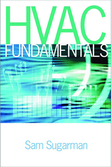
Introduction to HVAC Control SystemsControllerControlledDeviceProcessPlantInput Signal (setpoint)5ToControlledVariable SensingElement(Feedback)Figure 1-1Diagram of Control LoopIn this example, you are acting as the controller making the controldecisions whether to press or release the accelerator. The car’s speed is thecontrolled variable and the speedometer is the sensor that measures the current value or control point of the controlled variable. The accelerator is thecontrolled device and your car’s engine is the process plant.Figure 1-1 shows this exchange of information schematically (see alsoTable 1-1).It is called a control loop because information flows in a circle from thesensor (the speedometer) measuring the controlled variable (speed) to thecontroller (you) where the current value of the controlled variable (the controlpoint) is compared to the desired value or setpoint. The controller then makesa control decision and passes that on to the controlled device (the accelerator)and to the process plant (the car’s engine). This then has an effect on thecurrent value or control point of the controlled variable, starting the processall over again. All control loops include these essential elements.Figure 1-2 illustrates the components of a typical HVAC control loop.Shown in Figure 1-2 is an air-heating system utilizing a heating coilprovided with steam, hot water, or some other heating source. Cold air isforced through the system using a fan and heated to some desired temperature to maintain its setpoint.The intent of this control is to maintain a desired supply air temperature.As described in Figure 1-2 and Table 1-1, the sensor measures the temperatureof the supply air (the controlled variable) and transmits this information tothe controller. In the controller, the measured temperature (the control point)is compared to the desired temperature (the setpoint). The difference betweenthe setpoint and the control point is called the error. Using the error, the controller calculates an output signal and transmits that signal to the valve (thecontrolled device). As a result of the new signal, the valve changes positionand changes the flow rate of the heating medium through the coil (the processplant). This, in turn, changes the temperature of the supply air. The sensorsends the new information to the controller and the cycle is repeated.Both of these examples are called closed-loop or feedback-control systemsbecause we are sensing the controlled variable and continuously feeding that
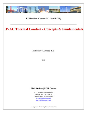
6Fundamentals of HVAC Control SystemsTable 1-1 Control Comparison for Automobile and HeatingTermAutomobileExampleHeating leddeviceThe acceleratorThe device thatprovides asignal to thevalveSupply airtemperaturesensorThe controlvalveControlledvariableProcessplantThe car speedInput signal(setpoint)The car engineDesired speedSetpointDefinitionThe supply airtemperatureThe heating coilSupply airsetpointCThe device that provides asignal to the controlled devicein response to feedback fromthe sensorThe device that measures thecurrent status of the controlledvariableThe device that changes theoperation of the process plantin response to a control signalThe signal that the sensor sensesThe device that produces thechange in the controlledvariableThis is the reference or desiredinput that is compared to thecontrolled variableControllerSensorControlledDeviceTSupply Air Temperature(Controlled Variable)HeatingCoilAir Flow(ProcessPlant)Figure 1-2Simple Heating Systeminformation back to the controller. The controlled device and processplant have an effect on the controlled variable, which is sensed and fed tothe controller for comparison to the setpoint and a subsequent responsein the form of a change in controller output signal.
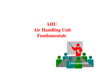
Introduction to HVAC Control Systems7An open-loop control system does not have a direct link between the valueof the controlled variable and the controller: there is no feedback. An exampleof an open-loop control would be if the sensor measured the outside airtemperature and the controller was designed to actuate the control valve asa function of only the outdoor temperature. The variable (in this case, thesupply air temperature or perhaps the temperature of the space the systemserved) is not transmitted to the controller, so the controller has no directknowledge of the impact that valve modulation has on these temperaturesmodulating the valve.Another way of defining an open-loop is to say that changes to the controlled device (the control valve) have no direct impact on the variable thatis sensed by the controller (the outdoor air temperature in this case). Withan open-loop control system, there is a presumed indirect connection betweenthe end-result and the variable sensed by the controller.If the exact relationship between the outdoor air temperature and the heating load was known, then this open-loop control could accurately maintaina constant space temperature. In practice, this is rarely the case and, therefore,simple open-loop control seldom results in satisfactory performance. For thisreason, almost all HVAC continuous-control systems use closed control loops.Open-loop control, in the form of time-clocks, or occupancy sensors, arevery common but they are on/off not continuous controls. One formof open-loop control commonly used is called reset control. In reset controlan open-loop is used to provide a varying setpoint for a closed control loop.For example, an open-loop can be arranged to adjust the heating supply watertemperature based on outside temperature, as shown in Figure 1-3. As theoutside temperature falls, the open-loop output rises based on a predetermined schedule, shown in the table in the Figure 1-3. This open-loop outputprovides the setpoint for the boiler.The advantage of this reset control is that the capacity of the heating systemincreases as the load increases, greatly improving controllability. This use ofone control loop to provide input to a second control loop is generally calledcascading and other examples will be mentioned later in the course.These examples describe the essential elements in any control loop: sensor,controller, controlled device, and process plant. Very few control systems areas simple as these examples, but every control system must include theseOUTDOORTTBOILERTable 1 TYPICAL RESETSCHEDULEOUTDOOR HOT WATERTEMP., C SERVICE, C 20851560BURNERFigure 1-3Boiler Reset Control
8Fundamentals of HVAC Control Systemsessential elements. In Chapter 5 we will describe more complex systems, butall of them will be based on elementary control loops. Behind any apparentcomplexity, there must be an elementary system or systems.Sometimes the sensor and controller are combined in one package. Thissensor/controller combination is commonly called a stat, such as a thermostat,humidistat, or pressure stat. These devices still contain the individual controlelements (the sensor and the controller); they have simply been mounted intoa single enclosure.Common controlled devices include control valves, which are used to control the flow of water or steam, and control dampers, which are used tocontrol the flow of air. These devices and their proper selection are discussedin Chapter 3. Motor starters, relays, and variable speed drives are alsocommon control devices; they are discussed in Chapter 2.Common controlled variables include the temperature, humidity, pressure,and velocity of air in conditioned spaces and in ductwork, and the temperature, velocity, and pressure of water in hydronic heating and cooling systems.Sensors used to measure these variables come in a variety of types withvarying degrees of accuracy. The accuracy of the measurement naturallyaffects the accuracy of control. Sensors are discussed in Chapter 4.Typically, between the controller and the controlled device, there is anactuator attached to the controlled device through connectors called the linkage. Actuators are devices that convert the signal from the controller into aphysical force that causes the controlled device (damper or valve) to move.Actuator characteristics vary by the type of control system used and arediscussed in Chapters 6 through 10.This section introduced some fundamental terms used in control systems. It isvery important that these terms are well understood so that you understand theremaining sections of this chapter. The following is a summary of key terms:Controlled variable: the property that is to be controlled, such as temperature,humidity, velocity, flow and pressure.Control point: the current condition or value of the controlled variable.Setpoint: the desired condition or value of the controlled variable.Sensor: the device that senses the condition or value of the controlled (or“sensed”) variable.Sensed variable: the property (temperature, pressure, humidity) that is beingmeasured. Usually the same as the controlled variable in closed-loopcontrol systems.Controlled device: the device that is used to vary the output of the processplant, such as a valve, damper, or motor control.Process plant: the apparatus or equipment used to change the value of thecontrolled variable, such as a heating or cooling coil or fan.Controller: the device that compares the input from the sensor with thesetpoint, determines a response for corrective action, and then sendsthis signal to the controlled device.Control loop: the collection of sensor, controlled device, process plant, andcontroller.Closed-loop: a control loop where the sensor is measuring the value of thecontrolled variable, providing feedback to the controller of the effectof its action.
Introduction to HVAC Control Systems9Open-loop: a control loop where the sensor is measuring something otherthan the controlled variable. Changes to the controlled device andprocess plant have no direct impact on the controlled variable. Thereis an “assumed” relationship between the property that is measuredand the actual variable that is being controlled.1.4 Control ModesThe purpose of any closed-loop controller is to maintain the controlledvariable at the desired setpoint. All controllers are designed to take action inthe form of an output signal to the controlled device. The output signal is afunction of the error signal, which is the difference between the control pointand the setpoint. The type of action the controller takes is called the controlmode or control logic, of which there are three basic types: two-position control floating control modulating control.Within each control-mode category, there are subcategories for each of thespecific control algorithms (procedures, methods) used to generate the outputsignal from the error signal, and other enhancements used to improveaccuracy.The various control modes and subcategories are simply different waysof achieving the desired result: that the controlled variable be maintained atsetpoint. It is often a difficult task because the dynamics of the HVAC system,the spaces it serves, and the controls themselves can be very complex.There are generally time lags between the action taken by the controller andthe response sensed by the sensor.For instance, in the heating system depicted in Figure 1-2, it takes time forthe valve to move when given a signal from the controller; then it takes alittle more time for the water to begin to flow. If the coil has not been usedin a while, it will take time to warm its mass before it can begin warmingthe air. If the sensor was located in the space served by the system (asopposed to in the supply duct, as shown in Figure 1-2), there would be evenmore time delays as the air travels down the duct to the diffusers and b
Welcome to the ASHRAE Learning Institute’s Fundamentals of HVAC&R eLearning System Series. This is a Course Reader to accompany the Fundamentals of HVAC Control Systems online modules. To help you learn at your convenience, this Course Reader is also ava