Transcription
USER'S GUIDE TO1IRECT00Lo IGITAL, ONTROLOF HVAC EQUIPMENT74: byR.E KirtsSEDTICLECTEDEC 261989Sponsored by the Naval Facilities Engineering CoiQandNaval Civil Engineering LaboratoryPort Hueneme, California93043pmforOL48C2C4ittcilmltd0 60
CONTENTSfPageI.II.III.IV.V.INTRODUCTION .BACKGROUND .FUNDAMENTALS .1.2APPLICATIONS .SUMMARYREFhRENCES .1.35.65.67. .APPENDIXESA - Proportional-Integral-DerivativeControl . .A-1B - Control System Tuning . B-IiAccesion l BY:':Oistribtotion I:Avaitabfitty Codes:DistAvail awldjorSpecial
INTRODUCTIONHeating, ventilating, and air conditioning(HVAC) systems are now under going the most significant change in control technology in the past100 years. This change is the introduction ofdirect digital control (DDC) to HVAC systems.Computer control has been introduced to manythings over the past few years, from automobileengines to home appliances to most industrialprocesses, but only recently have small computercontrol systems been introduced into the spaceconditioning industry. To understand the implications of this new HVAC control technology, itis necessary to consider several questions: :4at is DDC and what are its capabilities?QUnder what conditions is DDC a costeffective alernative to conventionalcontrol? &44-What constitutes good system design andinstallation practice?This report addresses these questions bypresenting information which describes DDC, presents its advantages and disadvantages, and givesapplications guidance. II. BACKGROUNDDirect digital control is becoming an important factor in the new construction and retrofitmarket for HVAC controls for several reasons:energy savings through improved control, improvedcontrol system reliability, and easier maintenance.IIiI,1
As applied to HVAC systems, direct digitalcontrol is direct computer control of a devicesuch as a valve or damper actuator. In a DDCsystem, the computer accepts data from sensorsmeasuring variables such as temperature, humidity,and pressure, performs calculations on thesedata to determine the correct output response,then sends a control signal directly to the controlled device.DDC has been expanding into the chemical,food, and metals process industries steadily forabout the past 10 years until today it has virtually supplanted conventional pneumatic controllers. In the process, DDC has proven itself tobe reliable, flexible, easy to use and maintain,and cost effective. Where and when a DDC controlsystem should be installed in an HVAC system is,at the present time, a function of the complexityof the system to be controlled. At the presenttime, DDC is most cost effective in larger,complex HVAC systems, but the HVAC system sizefor cost effective DDC application is rapidlydecreasing.III. FUNDAMENTALSWhat is DDC?Direct digital control uses a programmabledigital computer to process information for thepurpose of determining the correct control action.The input information for the computer comesfrom analog sensors (such as temperature sensors)and digital sensors (such as switches). Thisinformation is used as variable data in a predetermined sst of instructions called the control progran. -roe control program calculatesfor control parameters and takesdifferent val.different paths in the logic of the programdepending upon the values of the input variables.2j?
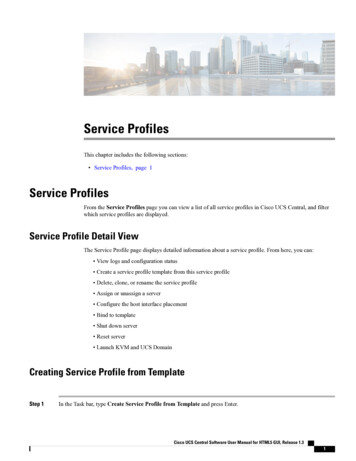
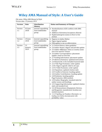
--After the computer completes its calculations,the appropriate value of control signal is outputeither in analog form (such as a voltage between0 and 10 volts) or in digital form (such as aswitch closure). The complete input-calculationoutput sequence is usually repeated several timesevery minute. Because of this repetitive ratherthan continuous processing of input data, a DDCcontrol system is called a "sampled data system."These concepts are illustrated in Figure 1.The word "direct" in direct digital controlimplies that the controller has immediate controlover the final control element. This is in contrast to a conventional energy monitoring andcontrol system (EHCS) in which a computer actsonly through a conventional pneumatic or analogelectronic control system to actuate the finalcontrol element.The word "digital" in direct digital controlmeans that input data are converted into digitalform, i.e., a discrete number, so that they maybe operated on by a sequence of instructionscalled a computer program. The output from theprogram is also a number, which may be displayedon an output device for information purposes orconverted to a continuous (or analog) outputsuch as a voltage.Direct digital control should not be confused with analog electronic control (Figure 2).An analog electronic controller is the electronicequivalent of a conventional pneumatic controller.As a consequence, each analog electronic controller is designed to perform only one specificfunction. Thus, an UVAC control system whichuses analog devices must be built up from a numberof interconnected special purpose devices toobtain the desired system performance. Analogelectronic devices use operational amplifiers,voltage dividers, and other analog components to3
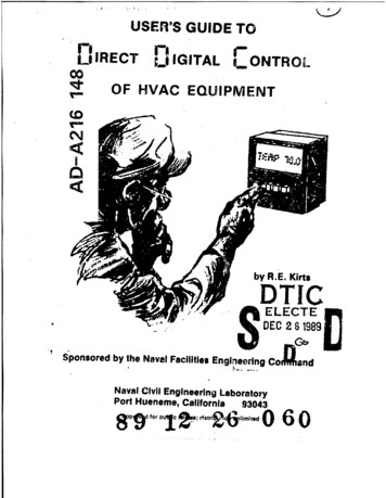
produce an output signal which hat. A fixed relationship to the input signal. For example, theoutput might be the difference between two inputsignals multiplied by a constant. The output isalso a continuous function of the input. Thisis to be contrasted with a DDC controller inwhich a computer "takes a Jook" at the inputs,follows one of several different logical pathsdepending upon the values of the inputs, an dgenerates an output (or outputs) accordingly.Figures 1 and 2 illustrate these differences.What's the difference between DDCand an EMCS System?*A conventional energy monitoring and controlsystem is used when centralized monitoring and asupervisory level of remote control are desiredin an HVAC control system. A central computercommunicates with a remotely located electronicdevice (usually called FID, for field interfacedevice) which provides the computer with data onlocal conditions, such as temperature or motorstatus, and which can relay signals from thecentral computer to the local HVAC control systemto do things such as change the set point of apneumatic two-input controller. An EMCS systemis usually designed to provide detailed statusand alarm reports and log system data for trendanalyses and energy savings calculations. Thekey distinction to be made is that in an EMCSsystem, control of the individual devices (suchas valves, dampers, or fan speed) remains with alocal, more or less independent, control system.These local control systems are often called"local loop controllers." The local loop controllers may be either pneumatic, electric, analogor digital electronic. Thus, a DDC localloop controller may or may not be connected toan E CS system. The relationship between DDCand EMCS is illustrated in Figure 3.t4
Sensor0010000actuatorSpecial circuits convertanalog signals to digitalform for use by computer(and vice versa)DIADigital computerIperiodicallysamples sensor,performs controlcalculation, andcontrolcalculationFigure 1. A digital control system.I I,.-m. ,5outputs the
sensor000000000actuator,:-Input-Uandoutput signalsare continuousrather thanpeiodcAnalog electronictemperaturecontrollerFigure 2. An analog control system.
(BASE -WIDEEMCSCOORDINATINGCOMMANDS ARESENT DOWN THECONTROLHIERARCHYSINGLEBUILDINGEMCSSYSTEM STATUSAND DATA ARESENT UP THEHIERARCHYIIFIELDINTERFACES DEVICE,(,OPTIONAL)DIRECT DIGITALLOCAL LOOPCONTROLIF FUNCTIONING OF LOCAL CONTROL IS INDEPENDENTOF OTHER DEVICES, CONTROL IS SAID TO BEDISTRIBUTED CONTROLFigure 3. Relationship between DDC and EMCS.l Inl llll lllllIunnn,7
What are the Advantages andDisadvantages of DDC?The major advantage of direct digital controlis that one programmable unit can be made toperform almost an infinite variety of controlfunctions. If, at some later date, the controlsystem needs to be modified, changing a DDC systemis mostly a matter of changing the computer program, whereas changing a pneumatic or analog electronic control system could require majorreplacement and rewiring of components. This isillustrated in Figures 4 and 5 where pneumaticand DDC control systems are compared in the sameapplication.Another point illustrated by the informationpresented in Figures 6 and 7 is that of accessto control system documentation. In actual practice, it is often difficult to find current andaccurate drawings for a conventional, built-upcontrol system such as that illustrated in Figure 4. Data on setpoints, reset schedules, andevent timing, such as that presented in Figure 6,are often even more difficult to find. In contrast, the "as-built" drawings for a DDC controlsystem are always available in the form of theIn additioncomputer program code (Figure 7).to the control logic, setpoint and other dataare readily available. Program logic, setpointand schedule data, and other information storedin a DDC unit can be displayed on a video terminal or printed when the control documentationneeds to be examined or recorded.8
BfillEll-Jill
26Uo.13110iEPl
FAN CONTROLThe fan control circuit shall include safety controls,a hand-off-auto switch, timer energized controls, and amanual override switch.Safety controls shall consist of an emergency disconnectswitch mounted in the mechanical room, a manual reset freezestat, a supply air smoke detector, and a return air smokedetector.With all safety controls closed and the hand-off-autoswitch in the auto position, the fan shall be controlled bya seven day timer.With the fan off, should the space temperature fallbelow 550 F, night thermostat shall restart the fan.A manual override switch, located in the occupied space,shall, when activated, restart the fan for a timed period of1 hour.FAN CONTROL AND TENPERATURE CONTROL INTERLOCKAC power and DC power to each component in the systemshall be interrupted whenever the fan circuit is de-energizedor there is no air flow as sensed by air flow switch, AF.MIXED AIR SECTIONMixed air sensor, SM, through controller, TCM, shallmodulate the outside air and return air dampers to maintaina mixed air temperature of 60*F 3*F.With the system in the occupied mode, the minimumposition switch, NP, shall insure the quantity of outsideair is not less than 10% of the total CFM. When the systemis in an operating but unoccupied mode, the minimum positionswitch shall be removed from the circuit.High limit switch, HL, shall return the system to minimumoutside air (occupied) or zero outside air (unoccupied) whenever the outside air rises above 70*F.Figure 6. Sequence of control for pneumatic system.(See Figure 4 for nomenclature.)11km.
Whenever the zone requires less cooling than the mixedair section is providing, the discriminator, LSS, shall passcontrol of the OA/Rh dampers to the zone controller.HEATING COILZone sensor, SZ, through controller, TCZ, andsequencer, SQl, shall modulate the hot water valve from fullheat to no heat over a zone temperature range of 66 F to700F.COOLING COILZone sensor, SZ, through controller, TCZ, andsequencer, SQ2, shall modulate the chilled water valve fromno cooling to full cooling over a zone temperature range of76*F to 80 F.Figure 6. Continued.12Iitji llDi-
c u st.alcAAcoLLM"-I.tlLIWFIA4:r"lA l TIII"h l-qC--u.-t ltLe0 ) en I-I.0IF(M.41 TIJ)MIl.T0.IFIDVA .s AP.07*117*tLFe0e.IAIAR)).ssbtCWtty) OlWI I)etl1)telcptCALWWIL.0)SAAMt ITl.WF-100)0)CR.--e1!, .5e00AtAA44SIts.0 -R ,IRICOOCS'AlR :ITAeiAWA.tA1v.rFA.;) .,F4P'AL,tSCA UPDaIW1)-I RCARL.eDn.ysem7.b 4:IAt 13.rLARL 4:Apla51t
Control system changes are much easier toimplement with DDC than with conventional controlsystems. Changes to a DDC control system aremade by changing the computer program and, perhaps, changing a sensor or actuator. Changes toa pneumatic or analog electronic control systemusually require extensive rework of the controlpanel, including component replacement and rewiring or repiping. This is because the controllogic of a built-up control system, such as apneumatic system, is composed of many discrete,special purpose devices with the logic "hard-wiredin" by means of the interconnecting wire or pipes.This makes changing the system difficult andexpensive. Figure 8 presents a typical controlschematic for a small pneumatic system. Eventhis small system consists of more than 80 discrete components. It is often difficult to determine the control logic and operating sequencefrom control diagrams such as Figure 8. Also,the original "as-built" control schematic may nolonger be very representative of the actual control system installation.A significant advantage of direct digitalcontrol systems is the energy savings achievablethrough improved control of RVAC systems.Improved control is achieved in two ways: betterfeedback control algorithms, and more sophisticated control strategies.A major advantage of DDC is the ease withwhich proportional-integral-derivative (PID) andother advanced control algorithms can be implemented. Most pneumatic and analog electroniccontrollers offer only proportional control. Inproportional control, the output of the controlleris made proportional to the difference betweentwo inputs: one is the setpoint and the otheris the measured variable. The problem with proportional control is that corrective action (i.e.,an output from the controller) occurs only after15
a measurable error occurs between the input andthe setpoint. This results in loose control anda steady state offset error, or control droop.Addition of integral controlSee Figure 9.eliminates the offset error and improves controlresponse. Integral control eliminates thesteady state error by generating an outputsignal proportional to the accumulated error.In some control applications, it is important toconsider
(HVAC) systems are now under going the most signi-ficant change in control technology in the past 100 years. This change is the introduction of direct digital control (DDC) to HVAC systems. Computer control has been introduced to many things over the past few years, from automobile engines to home appliances to most industrial processes, but only recently have small computer control systems .