Transcription
HVAC Fundamentals
When you have completed thissection, you will: Be familiar with Basic HVAC terminology Understand the fundamentals of therefrigeration cycle Know the four major components of an HVACsystem and be able to explain each function Be knowledgeable about low voltage controls
When you have completed thissection, you will: Be aware of workplace safety measureswhile servicing a system Know how to use electrical test equipment Have practiced wiring controls andtroubleshooting Have practiced charging a system
Air Conditioning Theory:Principle #1: Cold is defined as “the absence of heat”. EverythingHEATabove absolute Zero is a measurement ofPrinciple #2: Heat is ever ready to flow to anything, which containsLess Heat.Principle #3: Anytime a liquids change to a gas vapor, it must giveup its heat and the heat is carried off in theVapor.
4 Major Componentsof an A/C System Compressor: “compresses” or squeezes low temperature/lowpressure vapor in order to raise it to a higher temp and pressure.Expels Condenser: The condenser is a device thatheatfrom the system.Absorption of Evaporator: The evaporator is a device for theheat into the system.Flow of Metering Device: The metering device controls therefrigerant into the evaporator.
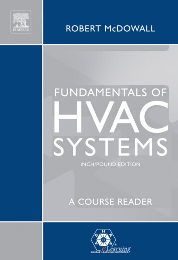
Basic Cooling CycleNormally, a refrigerant picks up heat by evaporating andthen gives up heat by condensing.Two important things to remember about Freon refrigerants are:1. Refrigerants boil at a very low temperature.2. There is a direct relationship between the temperature of arefrigerant and the pressure of a refrigerant.The condensing unit (located outdoors)contains three basic components. They areFan Motor , andthe Compressor ,the Coil .
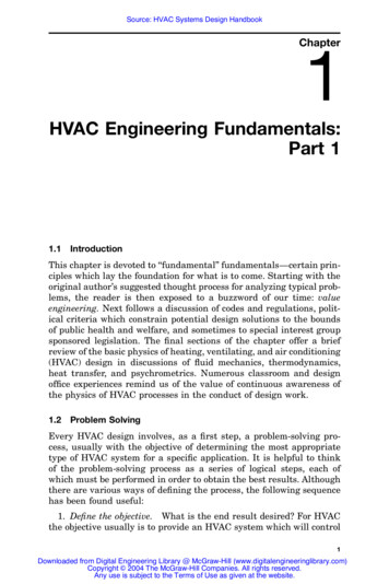
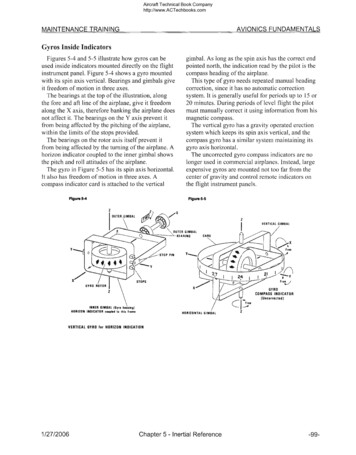
Functions of the 4 MajorComponentsCompressorCondenserMetering deviceEvaporator The compressor isthe workhorse of thesystem. It draws heat-ladengas from theevaporator at lowtemp/low pressureand compresses thisgas, raising its temp/pressure to the pointat which the gas willcondenseThe condenser is thecomponent in whichthe heat absorbed inthe evaporator istransferred to theatmosphere throughthe condensercooling medium.Typically, water orairThe metering deviceis located before theevaporator coil. Itmay be a cap tube,expansion valve, or apiston. It meters theproper amount ofliquid to the coil andmaintains a liquidseal between the highand low side of thesystem.The evaporator is thecooling component ofthe system. In theevaporator, pressureis reduced and theliquid boils to a gas atlow temperature as itabsorbs heat from thesubstancessurrounding the coilsuch as conditionedspace.
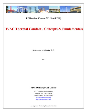
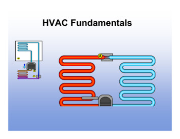
Summary of the Cycle453Flow216
Low Voltage Controls Typically 24 volts is the operating voltage for HVACcontrols.Transformer 240 volts is delivered to a ,there it is stepped down to 24 volts A/C After that, one common wire is connected to one sideof the coil on all of the controls.Thermostat The determineswhich wires willcomplete a circuit while delivering 24 volts to a relay,contactor, or sequencer.
Transformers
Transformers A transformer produces an electrical current through electromagneticInduction A step-down transformer has more turns ofPrimary and less on thewire on theSecondary coil
Transformers A transformer can be diagnosed by checking forand/orVoltageContinuity In a good transformer there should be continuityAllbetween wireson each coil.No Continuity between the primary coil and There isthe secondary coil. If there is no continuity between any wires on thesame coil the transformer is .Bad
Thermostatsa JumperThe simplest way to test a thermostat is to useR to YCooling Cyclewill energize theR to GEvaporator Fan Motorwill energize theR to WHeat Cyclewill energize the
Thermostats If a thermostat works with a jumper wire and does notwork without the jumper the thermostat is bad.24 Volts is present and the jumper does not turn on Ifthe air handler or condenser it is time to troubleshootthe air handler or condenser to determine the problem.
Relays The purpose of a relay is to control aValveSwitch,Motoror. A relay is designed forLight Duty starting applications. The simplest way to check a relay is to listen for a click and then24 Volts. If no click, check to see if24 Vis present to activate the coil.SPST NOSPST NCDPST NO It is not uncommon for a relay contact to stick due toOverload .
Contactors A contactor is a large version of a relay designed for aheavier duty. Since a motor in start mode draws up to 4 Timesmore current than while in run mode a contactor isused.Single PoleDouble Pole Typically aor ais used in residential HVAC systems.
Contactors A simple way to test a contactor is to push theHigh Voltagecontacts together or check for voltagewhen the contacts are pulled inCheck forcontinuityOr check if 24volts is present Why is it important to be certain that a replacementcontactor has the same amperage rating?Prevent Fire/ Damage/ Overload It is not uncommon to find ants covering the contacts
Manifold Gauges Gauges measure input pressure, output pressure, andthe related temperature. A set of gauges will Confirmwhat is taking placewithin the field system. Without a set of gauges one may only guess what istaking place in the sealed system.
Manifold Gauges Compound gauge: Blue - This is on theside of the system!Low High pressure gauge: Red - This is on the Highside of the system and is used to measure pressureper square inch. The service port is to add or remove refrigerant andPull a Vacuum. The manifold has three ports compound, pressure, andservice.
Temperature and PressureWhat Psi.is at 32degrees?90/90 ruleof 30 Over
Troubleshooting Example one: Compound gauge reads 80 psigand the pressure gauge reads 130 psig.Washout Bad - Compressor Example two: Very high pressure one the highside and low pressure on the low side.Restriction – Cap Tube Example three: Low pressure on the high sideand low pressure to a vacuum on the low side.Low Refrigerant Charge
Troubleshooting Example four: Compound gauge rises steadilyand then falls off rapidly. This continues throughseveral system cycles.Dirty Drier or Evaporator Coil Example five: A near normal low pressure andan unusually high head pressure.Dirty Condenser Coil If a gauge is out if adjustment or does notmeasure well, replace the gauge. You’ll knowwhen your gauges are faulty whenDisconnected there is a readingCannot be calibrated to zero
Proper Charging Procedures1.Always purge lines - To prevent moisture fromentering the system.2.Charge with vapor only - Do not turn the tank over. Itwill “slug” the compressor (fill it with liquid) and ruin it.3.Charge on vapor side only - Using the compoundgauge’s service port.4.Charge unit only while it is running - Because thesuction pressure will be low enough to allow refrigerantto enter the system. If it is NOT running you cannotknow if it has a low charge as the pressure isequalized.
Proper Charging Procedures5. To avoid freezing condensate water - Always attemptto charge to a desired evaporator temperature (36 orabove) regardless of temperature outside.6. A desirable difference in temperature is 15-20 F Take the time to explain to the resident that themaximum differential is 20 to the ambient temperatureoutside.
Review Questions1. What is the definition of law two?Heat is always ready to transfersomething that has less heat2. What are the four major components ofan A/C system?Compressor, Condenser, MeteringDevice, and Evaporator
Review Questions3. In which component of the A/C system isheat absorbed?Evaporator4. What is the function of the thermostat?To complete or interrupt a controlcircuit5. What units of measure are used for avacuum?Inches of Mercury hg
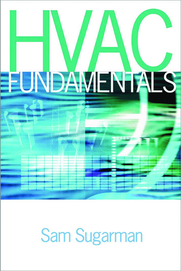
Wiring a Transformer Blue and Yellow 24 volts Orange And White 24o volts Red and Black 208 volts Black and White 120 voltsBlue24 volts A/C Secondary WindingYellowOrange240 VoltsRed208 VoltsPrimaryWindingBlack120 VoltsWhiteCommon
Wiring a Thermostat505560657075808590What does eachcolor control?HeatFanOffOffCoolAuto Red50 55 60 65 70 75 80 85 90 95 24 Volts Green Indoor Fan White HeatRed Yellow CoolingGreenWhiteYellow
Wiring a RelayNormally OpenContact531Normally ClosedContact6423&4NO Contact with terminal numbersA/C Connects to theNC Contact with terminal numbers1&2Heat Connects to theHigh speed Heat should be on speedLowA/C should be on
Wiring a CompressorContactorL 1L 224VHermCom35 ufFan24 Volts5 uf35/5 ufDual capacitorCompressorCommonStartRun240VoltsA/C
Wiring a Hard Start CapacitorTo which terminals do the leads connect?SuperBoostHerm & CommonWhat is the purpose of this component?Temporary extra Start PowerFor ½ to 5 hpCompressorsA super boost provides 4 Timesmore than the amount of power of aregular capacitor.
HVAC Fundamentals Be familiar with Basic HVAC terminology Understand the fundamentals of the refrigeration cycle Know the four major components of anHVAC system and be able to explain each function Be knowledgeable about low voltage controls When you have completed this section, you will: When you have completed this section, you will: Be aware of workplace safety measures .File Size: 383KBPage Count: 31