Transcription
AHUAir Handling UnitFundamentalsj.ilangumaran
Objectives Review primary components of an AHU Understand the basic progression andadvantages of advanced AHU control Understand the basic control sequences Review key operating concepts
HVAC System in a Building
HVAC Air Systems HVAC air systems are made up of:––––––––AHU - Air handling unitsDampersCoils and ValvesFansDistribution ducts and terminal boxesPumps and PlumbingControl devices and control loopsUnitary equipment: fan coils,perimeter radiation, unit ventilators,unit heaters, etc.
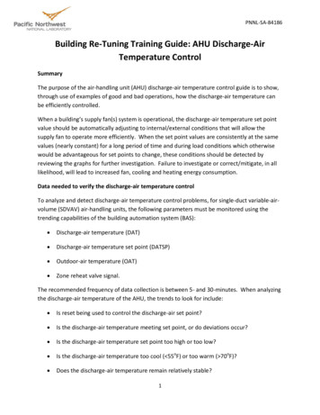
AHU - Components & TerminologyEARAReturn FromSpaceOAFilterDACooling CoilHeating
AHU componentsSupply fanMixed AirsensorMixed airdampers sectionReturn AirsensorHeating coil& valveCooling coil& valveDischarge airsensorDischarge airDuctReturn airDuct
AHU components
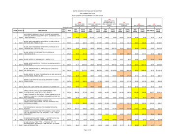
Types of Air HandlersAir Handling Units – Mixed Air
Types of Air HandlersAir Handling Units – Mixed Air
A “Single Duct” AHU variation The exhaust air damper is not in this airhandler; the building air is exhaustedelsewhere, but the basic mixed air and otherfunctions are unchanged.
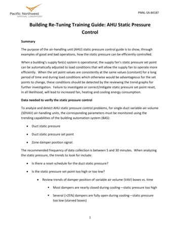
Air Handler ComponentsThe fan section withaccess door open.
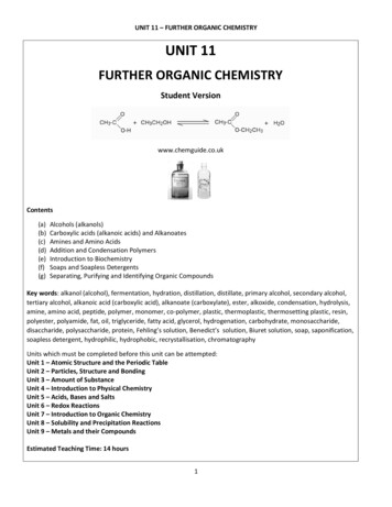
Air Handler ComponentsThe filter section.Notice the cross stacking ofthe filters to increasesurface area.
Air Handler ComponentsTemperature Sensor: Temperature sensors are used formeasurement of temperatur of aRoom, Air Duct, Hot /Cold Water,Outside Air etc. Models are available with PT1000,NTC20K, BALCO500 sensingelements.LF20 : AIR DUCT TEMP. SENSOR (NTC 20k)T7412 : ROOM TEMP. SENSOR (PT1000/NTC 20k)T7413A : IMMERSION TEMP. SENSOR (PT1000)
Air Handler ComponentsRelative Humidity Sensor: Relative Humidity sensors are usedfor measurement of Relativehumidity of a Room, Air Duct,Outside Air etc. Sensor Type : Capacitance Combined Relative Humidity andTemperature Sensors are availablewith PT1000, NTC20K,BALCO500 sensing elements.H7015 : DUCT RELATIVE HUMIDITY SENSORH7012 : ROOM RELATIVE HUMIDITY SENSOR
Air Handler ComponentsDifferential PressureSwitch: Differential Pressure switches areused for monitoring of Filter, Fan,Pump, Fire Damper, Water Flow,Air Flow Status of air handlingsystems.DPS1000 : AIR DIFFERENTIAL PRESSURE SWITCHTDIAP SERIS : AIR FLOW SWITCH
Air Handler ComponentsDifferential PressureSensors/Transmitter: Used for measuring diff. Pressure,positive pressure and vacuum.DPT1000 : AIR DIFF. PRESSURE TRANSMITTERST 3000 Pressure Transmitter
Air Handler ComponentsCoils :Heating CoilsCooling CoilsCoil Construction Copper with Aluminium fins, 13 Fins /inch Number of Rows, I.e 4/6/8depending on the latent heatload & Bypass Factor.
Air Handler ComponentsThe coil section of a AHU.Note:There may be a widevariety of actual configurations
Air Handler ComponentsValves & ActuatorsValve Types 2 Way or 3 WayActuator Types Motorised Magnetic PneumaticOperation On - Off,Floating,Modulating
Air Handler ComponentsHeat Recovery :A heat-recovery system isoften used in buildings where asignificant quantity of outdoorair is used. Several types ofheat-recovery systems areavailableRunaround systems Heat pumps Runaround systems Rotary heat exchangers Heat pipes.Heat Wheel
Air Handler ComponentsHeat Recovery : Heat Wheel
Typical AHU Damper Sequences Manually adjustablequantity of outdoorair: Similar to “Fixed”, butwith a user adjustmentdevice for adjustingdamper setting from 0% to100% outdoor air. No automatic control. W/WO exhaust or returnair ducts.
Typical AHU Damper Sequences Mixed Air Dampers: Mixes OA and RA to maintain amixed air setpoint via directacting controller. Modulates 0% to 100%. Provides ventilation for IAQ. Provides free cooling. Provides proper temperature forH/C coil operation. OA and EA dampers close viarelay with fan off. RA damper opens via relay withfan off.
Typical AHU Damper Sequences Example of operation:– Setpoint 55 deg.– MAT 55 deg. ProportionalController output 50% Fan On Dampers:––OA 50%RA 50%
Typical AHU Damper Sequences Example of operation ontemperature rise:– Setpoint 55 deg.– MAT 57.5 deg. Controller output 75% Fan On Dampers:––OA 75%RA 25% More outdoor air!
Typical AHU Damper Sequences Example of operationon temperature fall:––––Setpoint 55 deg.MAT 50 deg.Controller output 0%Fan On Dampers:––OA 0%RA 100% No outdoor air; no fresh airin the building!
Mixed Air Dampers with a Minimum Position Setting Maintains a “minimum”outdoor damper position via aminimum adjustment devicewhen building is occupied.(fan on) Meets IAQ coderequirements.
Typical AHU Damper Sequences - Mixed Air Example of operation ontemperature fall:– Setpoint 55 deg.– MAT 50 deg.– Controller output 0% Min. Position Setpoint 25% Fan On Dampers:––OA 25%RA 75%Even though the Mixed Air controller is sendinga control signal to completely close OA dampers,the minimum position controller or logic ismaintaining setpoint.Fresh air is maintained in the building!75%25%25%
Typical AHU Damper Sequences Economizer Override. of Outdoor Air: Requires an additional reverseacting controller in the outdoorair. Brings OA damper tominimum when outdoor airtemperature is high. Provides for economicaloperation of the cooling coil.50%50%
Typical AHU Damper Sequences Example of economizeroperation with lowoutdoor temp.– MA StPt 55 deg– MA temp 55 deg– MA controller out 50%– OA StPt 70 deg– OA temp 67 deg– OA controller out 100% Min. Pos. StPt 25% OA damper 50%:MA controller is in control ofthe OA damper due to OATacceptable for efficient use ofmechanical cooling.50%50%
Typical AHU Damper Sequences Economizer Override withoutdoor temperature high:–––––––MA StPt 55 degMA temp 55 degMA controller out 50%OA StPt 70 degOA temp 74 degOA controller out 0%Min. Pos. StPt 25% OA damper 25%:OA controller is in control of theOA damper due to OATunacceptable for efficientmechanical cooling.75%25%
Typical AHU Damper Sequences Enthalpy controlledoverride of Mixed Aircontrol: Total heat (enthalpy) ofoutdoor air is compared tototal heat of return air todecide which is moreeconomical for efficientcooling coil operation.
Typical AHU Damper Sequences Example of operationwith OA enthalpy lower: MA StPt 55 deg– MA temp 55 deg– MA controller out 50% OA humidity 35%OA temp 60 degRA humidity 39%RA temp 71 degOutdoor air enthalpy is lowerthan return air enthalpy, so relaypasses MA controller signal.Min. Pos. StPt 25%OA damper 50%
Practical Example100%Outside Air AHU :OA AHU Seq
Practical ExampleMixed Air AHU :Seq of Oper AHU
PlantChiller Plant
Chiller PlantChiller Plant systems are made up of:––––––Chiller/Condenser UnitChilled Water PumpsCondenser Water PumpsCooling TowersMakeup Water TankA/C Expansion Water TankTRANE Chiller
Chiller PlantChiller Plant Concept :
Typical Cooling Tower
Typical Chiller Plant
Example Chiller PlantSeq of OperCHILLER
Example Chiller Plant (THL New Building)
Example Chiller Plant
Boiler PlantBoiler Plant systems are made up of:– Boiler Units– Primary Pumps– Secondary PumpsTypical Firetube Boiler
Boiler Plant
Boiler Plant ExampleSeq of OperBOILER
Boiler Plant Example
Boiler Plant Example
end
Fundamentals j.ilangumaran. Objectives Review primary components of an AHU Understand the basic progression and advantages of advanced AHU control Understand the basic control sequences Review key operating concepts. HVAC System in a Building. HVAC Air Systems HVAC air systems are made up of: –AHU -Air handling units –Dampers –Coils and Valves –Fans –Distribution .