Transcription
APPROVED BY AICTE NEW DELHI, AFFILIATED TO VTU, BELGAUMDEPARTMENT OF ELECTRONICS & COMMUNICATIONENGINEERINGANALOG ELECTRONICS LABORATORYLAB MANUAL – 15ECL37III-SEMESTER2016-2017Prepared by:Reviewed by:Pavan V SAssistant ProfessorDept. of ECEGCEMKavitha M VHead of the DepartmentDept. of CSEGCEMApproved by:Dr. A.A. Powly ThomasPrincipalGCEM81/1, 182/1, Hoodi Village, Sonnenahalli, K.R. Puram, Bengaluru,Karnataka-560048.
CONTENTSS.NoTitlePage No1.Syllabusii2.Course objectiveiii3.Course outcomeiii4.Do‟s & Don‟tsiv5.List of experimentsv6.Viva questions47-487.Appendix-149-52
Analog Electronics Laboratory Manual - 10ESL37SYLLABUS1. Design and set up the following rectifiers with and without filtersand to determine ripple factor and rectifier efficiency:Full Wave Rectifier (b) Bridge Rectifier2. Conduct experiment to test diode clipping (single/double ended) andclamping circuits (positive/negative).3. Conduct an experiment on Series Voltage Regulator using Zener diode andpower transistor to determine line and load regulation characteristics.4. Realize BJT Darlington Emitter follower with and without bootstrapping anddetermine the gain, input and output impedances.5. Design and set up the BJT common emitter amplifier using voltage divider biaswith and without feedback and determine the gain bandwidth product from itsfrequency response.6. Plot the transfer and drain characteristics of a JFET and calculate its drainresistance, mutual conductance and amplification factor.7. Design, setup and plot the frequency response of Common SourceJFET/MOSFET amplifier and obtain the bandwidth.8. Plot the transfer and drain characteristics of n-channel MOSFET and calculateits parameters, namely; drain resistance, mutual conductance andamplification factor.9. Set-up and study the working of complementary symmetry class B push pullpower amplifier and calculate the efficiency.10.Design and set-up the RC-Phase shift Oscillator using FET, and calculate thefrequency of output waveform.11.Design and set-up the following tuned oscillator circuits using BJT, anddetermine the frequency of oscillation.a) Hartley Oscillator (b) Colpitts Oscillator12.Design and set-up the crystal oscillator and determine the frequency ofoscillation.Dept of ECE- GCEMPage ii
Analog Electronics Laboratory Manual - 10ESL37Course objectives:This laboratory course enables students to get practical experience in design,assembly, testing and evaluation of Rectifiers and Voltage Regulators. BJT characteristics and Amplifiers. JFET Characteristics and Amplifiers. MOSFET Characteristics and Amplifiers. Power Amplifiers. RC-Phase shift, Hartley, Colpitts and Crystal OscillatorsCourse outcomes:Through this course, the students: Acquire a basic knowledge in solid state electronics including diodes, MOSFET,BJT, and operational amplifier. Develop the ability to analyze and design analog electronic circuits usingdiscrete components. Observe the amplitude and frequency responses of common amplificationcircuits. Design, construct, and take measurement of various analog circuits to compareexperimental results in the laboratory with theoretical analysis.Dept of ECE- GCEMPage iii
Analog Electronics Laboratory Manual - 10ESL37LAB INSTRUCTIONSDo’s Ensure your presence five minutes before the commencement of the lab. Attend all the lab sessions without fail. Come well prepared for every lab session. Complete and Bring the Lab records regularly. Ensure the proper polarity of cables before connecting the kits. Ensure the checking of the circuit of circuit connections before turning ONthe circuit. Tuck in your shirts and not to play with instruments laid on the bench. Wearing loose garments inside the lab is strictly prohibited. You have to wear shoes compulsorily. Keep the space around you clear for others.Don’ts Don‟t bring the Cell phone and food items to Lab. Don‟t switch ON voltage supplies after making circuit connections in theabsence of the teacher. Don‟t rotate the Knobs unnecessarily.Dept of ECE- GCEMPage iv
Analog Electronics Laboratory Manual - 10ESL37LIST OF EXPERIMENTSSl No12345678910TitlePage NoRectifiersClippers and ClampersZener DiodeBJT AmplifiersBJT Darlington Emitter FollowerHartley and Colpitts oscillatorCrystal OscillatorClass B push –Pull amplifierJFET Characteristics1720232731384143JFET Common Source Characteristics47Dept of ECE- GCEMPage v
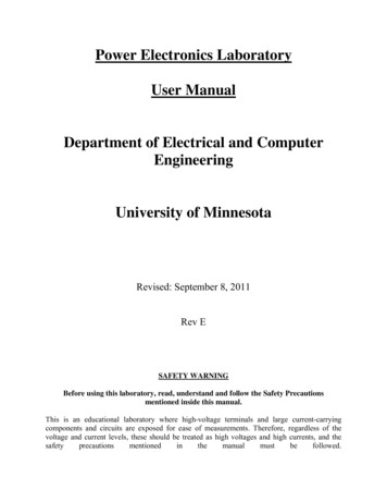
Analog Electronics Laboratory Manual - 10ESL37Experiment No : 1DATE :FULL WAVE RECTIFIERAIM:To study the full wave rectifier and to calculate ripple factor and efficiencyand Regulation with filter and without filter.COMPONENTS REQUIRED:Sl. No.Components , 470µf3.Power Resistance Board4.Step down Transformer5.CRO, Multimeter, Milliammeter, Connecting BoardQty2 Nos.Each 1 No.1 No.12 V1 No.THEORY:The center tapped full wave rectifier circuit is similar to a half wave rectifiercircuit, using two diodes and a center tapped transformer. Both the input halfcycles are converted into unidirectional pulsating DC.CIRCUIT DIAGRAM:FULL WAVE RECTIFIER WITHOUT FILTER CAPACITORStep /50HZ) A-0.1UF0RLA12VDept of ECE- GCEMVO(DC)VO(AC)KBY127Page 1
Analog Electronics Laboratory Manual - 10ESL37FULL WAVE RECTIFIER WITH FILTER CAPACITORStep 0HZ) AC2-00.1UF RLVO(DC)VO(AC)C1A12VK470UF -BY127DESIGN:Vin rms 12VVin m 2Vin rms 16.97VVO DC 2Vm/ 10.8VGivenVO DC 10VIO DC 100mARL VO DC / IO DC 100 Ripple r Vo rms / VO DC 0.48Design for the filter capacitorRipple 1/(4 3 f C RL)Given r .06C 1/(4 3 f r RL)RL 100 f 50Hz 470UFEfficiencyRegulation PDC /PAC % Regulation (I2DC * RL) / [(Irms)2 * (RL RF)]VNL VFL 100VFLPROCEDURE:1. Connections are made as shown in the circuit diagram2. Switch on the AC power supplyDept of ECE- GCEMPage 2
Analog Electronics Laboratory Manual - 10ESL373. Observe the wave form on CRO across the load resistor and measure the o/pamplitude and frequency.4. Note down RL, IDC, VODC , Vinac, Voac in the tabular column for different loadresistances.5. Calculate the ripple and efficiency and regulation for each load resistance.6. Repeat the above procedure with filter capacitor.TABULAR ncy RegulationWAVEFORMS:tVIN0-VO0Vo (Without Filter)tVCVo (with filter)tDept of ECE- GCEMPage 3
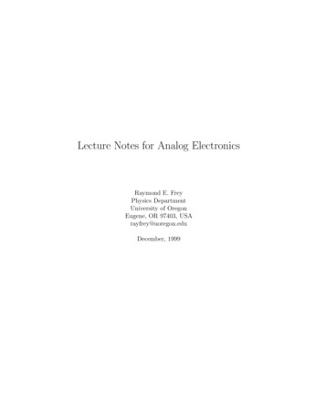
Analog Electronics Laboratory Manual - 10ESL37Experiment No : 1bDATE :BRIDGE RECTIFIERAIM:To study the bridge rectifier and to calculate ripple factor and efficiency andregulation with filter and without filter.COMPONENTS REQUIRED:Sl. No.Components , 470µf3.Power Resistance Board4.Step down Transformer5.CRO, Multimeter, Milliammeter, Connecting BoardQty4 Nos.Each 1 No.1 No.12 V1 No.THEORY:The bridge rectifier circuit is essentially a full wave rectifier circuit, usingfour diodes, forming the four arms of an electrical bridge. To one diagonal of thebridge, the ac voltage is applied through a transformer and the rectified dc voltageis taken from the other diagonal of the bridge. The main advantage of this circuitis that it does not require a center tap on the secondary winding of thetransformer; ac voltage can be directly applied to the bridge.The bridge rectifier circuit is mainly used as a power rectifier circuit forconverting ac power to dc power, and a rectifying system in rectifier type acmeters, such as ac voltmeter in which the ac voltage under measurement is firstconverted into dc and measured with conventional meter.CIRCUIT DIAGRAM:BRIDGE RECTIFIER WITHOUT FILTER CAPACITORStep /50HZ)02 - A-0.1UF 4RLVo312VDept of ECE- GCEMPage 4
Analog Electronics Laboratory Manual - 10ESL37BRIDGE RECTIFIER WITH FILTER CAPACITORStep downTransformerAmmeter(0-250mA)B RIDGE 112VAC(230 V/50 HZ)02 -AC2-0.1UF 4 RL3C1-12VVo47 0UFDESIGN:Vin rms 12VVin m 2Vin rms 16.97VVO DC 2Vm/ 10.8VGivenVO DC 10VIO DC 100mARL VO DC / IO DC 100 Ripple r Vo rms / VO DC 0.48Design for the filter capacitorRipple 1/(4 3 f C RL)Given r .06C 1/(4 3 f r RL)RL 100 f 50Hz 470UFEfficiency PDC /PAC (I2DC * RL) / [(Irms)2 * (RL RF)]RegulationDept of ECE- GCEM% Regulation VNL VFL 100VFLPage 5
Analog Electronics Laboratory Manual - 10ESL37PROCEDURE:1. Connections are made as shown in the circuit diagram2. Switch on the AC power supply3. Observe the wave form on CRO across the load resistor and measure theo/p amplitude and frequency.4. Note down RL, IDC, VODC , Vinac, Voac in the tabular column for different loadresistances.5. Calculate the ripple factor, efficiency and regulation for each loadresistance.6. Repeat the above procedure with filter capacitor.TABULAR ncy RegulationWAVEFORMS:Vin20t0- 20Vo0Vo (Without Filter)tVo (with filter)VCtDept of ECE- GCEMPage 6
Analog Electronics Laboratory Manual - 10ESL37Experiment No : 2aDATE :CLAMPING CIRCUITSAIM:Design a clamping circuit for the given output.COMPONENTS REQUIRED:Sl. No.Components DetailsSpecificationQty1.DiodesBY1271 No2.Capacitors0.1 F1 NoSignal generator, Cathode Ray Oscilloscope (CRO) withProbes, Dual Power Supply, Connecting BoardTHEORY:A clamper is one, which provides a D.C shift to the input signal. The D.Cshift can be positive or negative. The clamper with positive D.C shift is calledpositive clamper and clamper with negative shift is called negative clamper.Consider a clamper circuit shown below.0.1u- CD1VinVoBY 127In the positive half cycle as the diode is forward biased the capacitor charges tothe value VIN VD with the polarity as shown in the figure. In the negative halfcycle the diode is reverse biased. Hence the output is VO VIN VC .Initially let us assume that the capacitor has charged to VIN VD i.e.(5 – 0.5) 4.5VThen in the positive half cycle diode is forward biased and applying KVL tothe loop, Vin –VC –V0 0When Vin 0V0 Vin –VCV0 0 - 4.5 - 4.5VVin 5VV0 5 – 4.5 0.5VIn the negative half cycleWhen Vin -5VV0 -5 – 4.5 -9.5VThe output shifts between 0.5V and – 9.5V.Here the output has shifteddown by 4.5VDept of ECE- GCEMPage 7
Analog Electronics Laboratory Manual - 10ESL37The peak to peak voltage at the output of a clamper is the same as that ofthe input.CIRCUIT DIAGRAM AND DESIGN:Given Vin 10V (p-p)A] In the positive half cycle:Diode is forward biased.Applying KVL to loop 1Vin – VC – VD 00.1uVC Vin – VD- 5 - 0.5 4.5VCD1VinIn the negative half cycle:VoBY 127Vin – VC – V0 0V0 Vin – VCWhen Vin 0When Vin 5VV0 - 4.5VV0 0.5VWhen Vin -5V V0 -9.5VB]In the negative half cycle:Diode is forward biased0.1uApplying KVL to loop 1 -CVin VC VD 0VinVC - ( Vin VD)BY127D1VoVC - (-5 0.5) 4.5VIn the positive half cycle:Diode is reverse biased.Apply KVL to the loopVin VC – V0 0V0 Vin VCWhen Vin 0V0 4.5VWhen Vin 5VV0 5 4.5 9.5VWhen Vin - 5VV0 - 0.5VDept of ECE- GCEMPage 8
Analog Electronics Laboratory Manual - 10ESL37C] Assume VR 2VIn the positive half cycle:Diode is forward biased.Apply KVL to loop 1Vin – VC – VD – VR 0VC Vin – VD – VR0.1u 5 - 0.5 – 2- C 2.5VD1 BY127VinIn the negative half cycle:VoVRDiode is reverse biasedVin – VC – V0 0V0 Vin – VCWhen Vin 0VV0 - 2.5VWhen Vin 5VV0 2.5VWhen Vin -5VV0 -7.5VD] Assume VR 2VIn the positive half cycle:0.1uDiode is forward biased and the capacitor charges.Apply KVL to loop 1- CD1 BY127VinVin – VC – VD VR 0VoVRVC Vin – VD VR 5 –0.5 2 6.5VIn the negative half cycle:Vin – VC – V0 0V0 Vin – VCWhen Vin 0VV0 - 6.5VWhen Vin 5VV0 - 1.5VWhen Vin -5VDept of ECE- GCEMV0 - 11.5VPage 9
Analog Electronics Laboratory Manual - 10ESL37E]In the negative half cycle:Assume VR 2VDiode is forward biased and capacitor charges.Apply KVL to the loop1Vin VC VD VR 00.1uVC - ( Vin VR VD) - - (- 5 0.5 2)C 2.5VVinBY127D1VoFrom the fig. we see thatVRVin VC – V0 0V0 Vin VCWhen Vin 0V0 2.5VWhen Vin 5VV0 7.5VWhen Vin -5VV0 -2.5VF] VR 2V0.1uIn the negative half cycle:-Diode is forward biased and capacitor charges.Apply KVL to loop 1 CVinBY127D1VoVRVin VC VD - VR 0VC - ( Vin VD - VR) - (- 5 0.5 – 2) 6.5VFrom the circuit we see that,Vin VC - V0 0V0 Vin – VCWhen Vin 0VV0 6.5VWhen Vin 5VV0 11.5VWhen Vin - 5VV0 1.5VPROCEDURE:1. Rig up the circuit as shown in the circuit diagram.2. Give a sinusoidal input of 10V peak to peak3. Check and verify the output.Dept of ECE- GCEMPage 10
Analog Electronics Laboratory Manual - 10ESL37WAVEFORMS:Vin5V0t- 5VV00.50[A]t- 4.5- 9.5V09.54.5[B]0- 0.5tV02.50[C]- 2.5t- 7.5Dept of ECE- GCEMPage 11
Analog Electronics Laboratory Manual - 10ESL37V00- 1.5[D]t- 6.5- 11.5V07.52.5[E]0t- 2.5V011.56.5[F]1.50tRESULT :Dept of ECE- GCEMPage 12
Analog Electronics Laboratory Manual - 10ESL37Experiment No : 2bDATE :CLIPPING CIRCUITSAIM:Design a clipping circuit for the given values.COMPONENTS REQUIRED:Sl. No.Components DetailsSpecificationQty1.DiodesBY1271 No2.Resistors10 K 1 NoTHEORY:The process by which the shape of a signal is changed by passing the signalthrough a network consisting of linear elements is called linear wave shaping.Most commonly used wave shaping circuit is clipper. Clipping circuits are those,which cut off the unwanted portion of the waveform or signal without distortingthe remaining part of the signal. There are two types of clippers namely paralleland series. A series clipper is one in which the diode is connected in series withthe load and a parallel clipper is one in which the diode is connected in parallelwith the load.CIRCUIT DIAGRAM AND DESIGN:Assume Vin 10V (Peak to Peak)(a) Consider the circuit in fig. 1(a)VinD1BY127In the positive half cycle D is forward biased10kVo10kVo V0 Vin – 0.5 5 – 0.5 4.5 (0.5V is the diode drop)In the negative half cycle D is reverse biased V0 0V(b) Consider the circuit in fig. 2D1In the positive half cycle D is reverse biased V0 0VVinBY127In the negative half cycle D is forward biasedApplying KVL to the loop Vin VD – V0 0 V0 Vin VD -5 0.5 - 4.5VDept of ECE- GCEMPage 13
Analog Electronics Laboratory Manual - 10ESL37(c) Consider the circuit in fig. 3Given VR 2.5VIn the positive half cycle(i) When Vin VD VR , D is forward biasedApplying KVL, we getD1Vin VD VR V0V0 Vin – VD – VRVinVRBY12710kVo10kVoV0 5 – 0.5 – 2.5V0 2V(ii) When Vin VD VR , D is reverse biasedV0 0VIn the negative half cycle, D is reverse biasedV0 0V(d) Consider the circuit in fig. 4Assume VR 3VIn the positive half cycle, D is reverse biasedV0 0VIn the negative half cycle(i) When Vin VD VR , D is forward biasedApplying KVL, we getD1Vin - VD - VR V0V0 Vin VD VRVRBY127VinV0 -5 0.5 3V0 -1.5V(ii) When Vin VD VR , D is reverse biasedV0 0VDept of ECE- GCEMPage 14
Analog Electronics Laboratory Manual - 10ESL37(e) Consider the circuit in fig. 5Assume VR1 2.5V and VR2 3VIn the positive half cycle, D2 is reverse biased(i) When Vin VD1 VR1 , D1 is forward biasedApplying KVL, we getBY127Vin VD1 VR1 V0VR2D2V0 Vin - VD1 - VR1V0 5 - 0.5 – 2.5VinBY127 D12V0 2VVR110kVo1(ii) When Vin VD1 VR1 , D1 is reverse biasedV0 0VIn the negative half cycle(i) When Vin VD2 VR2 , D2 is forward biasedApplying KVL, we getVin - VD - VR V0V0 Vin VD2 VR2V0 -5 0.5 3V0 -1.5V(ii) When Vin VD2 VR2 , D2 is reverse biasedV0 0V(f) Consider the circuit in fig. 6During the positive half cycle, D is forward biasedV0 VD 0.5VDuring negative half cycle, D is reverse biased VinV0 VinDept of ECE- GCEM10kBY127D1VoPage 15
Analog Electronics Laboratory Manual - 10ESL37(g) Consider the circuit in fig. 7During positive half cycle,D is reverse biasedV0 VinDuring negative half cycle,10kVinD1VoBY127D is forward biasedV0 -VD -0.5V(h) Consider the circuit in fig. 8During positive half cycle10k(i) When Vin VD VR ,BY127D is forward biasedVinV0 VD VR 0.5 2.5V0 3V(ii) When Vin VD VR , D is reverse biasedV0 VinDuring negative half cycle, D is reverse biasedV0 Vin(i)Consider the circuit in fig. 9Assume VR 2.5VDuring positive half cycle,10kD is reverse biasedD1V0 VinBY127VinDuring negative half cycle(i) When Vin VD VR ,VRD is forward biasedApplying KVL to the loop, we getV0 -VD - VR - 0.5 - 2.5V0 -3V(ii) When Vin VD VR ,D1VoVR Vo-D is reverse biasedV0 VinDuring negative half cycle, D is reverse biasedV0 VinDept of ECE- GCEMPage 16
Analog Electronics Laboratory Manual - 10ESL37(j) Consider the circuit in fig. 10Assume VR1 VR2 2.5VDuring positive half cycle, D2 is reverse biased.(i) When Vin VD1 VR1 , D1 is forward biasedV0 VD1 VR1 0.5 2.5V0 3V10k(ii) When Vin VD1 VR1 ,D1D2D1 is reverse biasedBY127BY127V0 VinVinVoVoDuring negative half cycle,VR1VR2D1 is reverse biased1(i)When Vin VD2 VR2 , D2 is forward biasedApplying KVL to the loop, we getV0 -VD2 - VR2 -0.5 - 2.5V0 -3V(ii) When Vin VD2 VR2 , D2 is reverse biasedV0 Vin(k) Consider the circuit in fig. 1110kAssume VR1 3.5V and VR2 2VD2D1During positive half cycleBY127 VoVinBY127(i) When Vin VD1 VR1 D1 is forward biased andVR2VR1D2 is reverse biasedV0 VD1 VR1 0.5 3.5 4 V(ii) When Vin VR2 – VD2 D1 is reverse biased andD2 is forward biasedV0 -VD2 VR2 - 0.5 2 1.5VDuring negative half cycle,D1 is reverse biased and D2 is forward biasedV0 -VD2 VR2 - 0.5 2 V0 1.5VPROCEDURE:1. Rig up the circuit as shown in the fig.2. Give a sinusoidal input of 10V peak to peak.3. Check the output at the output terminal.4. To plot the transfer characteristics, connect channel 1 of the CRO to theoutput and channel 2 to the input and press the XY knob5. Adjust the grounds of both the channels to the centre.6. Measure the designed values.Dept of ECE- GCEMPage 17
Analog Electronics Laboratory Manual - 10ESL37WAVEFORMS:Series ClipperVin530t- 3.5-5VoVo4.5Vin(a)(b)0tVoVo0tVin- 3-1.5RESULT :Dept of ECE- GCEMPage 18
Analog Electronics Laboratory Manual - 10ESL37Shunt ClipperVin 50t 5Vo(f)0.5tVin0.5-5Vo4.5Vin(g) 0t0.5VoVO33.0(h)tVin-5Vo 5(i)0t-3.0Vin-3Vo 3(j)0Vint3.0-3Vo 41.5(k)Dept of ECE- GCEM0tVinPage 19
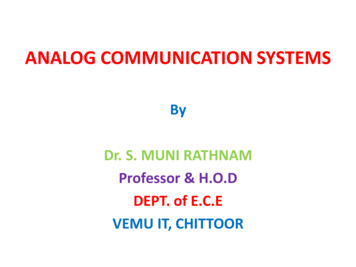
Analog Electronics Laboratory Manual - 10ESL37Experiment : 03DATE :ZENER DIODEAIM:To study zener diode as voltage regulator, To calculate % line regulation, Tocalculate % load regulation.APPARATUS: Zener diode, Resistors, Power supply, Multi meter.CIRCUIT DIAGRAM:THEORY:Zener diode is a P-N junction diode specially designed to operate in the reversebiased mode. It is acting as normal diode while forward biasing. It has a particularvoltage known as break down voltage, at which the diode break downs whilereverse biased. In the case of normal diodes the diode damages at the breakdown voltage. But Zener diode is specially designed to operate in the reversebreakdown region.Dept of ECE- GCEMPage 20
Analog Electronics Laboratory Manual - 10ESL37The basic principle of Zener diode is the Zener breakdown. When a diode isheavily doped, it‟s depletion region will be narrow. When a high reverse voltage isapplied across the junction, there will be very strong electric field at the junction.And the electron hole pair generation takes place. Thus heavy current flows. Thisis known as Zener break down.So a Zener diode, in a forward biased condition acts as a normal diode. In reversebiased mode, after the break down of junction current through diode increasessharply. But the voltage across it remains constant. This principle is used involtage regulator using Zener diodes The figure shows the zener voltageregulator, it consists of a current limiting resistor RS connected in series with theinput voltage Vs and zener diode is connected in parallel with the load RL inreverse biased condition. The output voltage is always selected with a breakdownvoltage Vz of the diode.The input source current, IS IZ IL . (1)The drop across the series resistance, Rs Vin – Vz . (2)And current flowing through it, Is (Vin – VZ) / RS . (3)From equation (1) and (2), we get, (Vin - Vz )/Rs Iz IL (4)Regulation with a varying input voltage (line regulation): It is defined asthe change in regulated voltage with respect to variation in line voltage. It isdenoted by „LR‟. In this, input voltage varies but load resistance remains constanthence, the load current remains constant. As the input voltage increases, formequation (3) Is also varies accordingly. Therefore, zener current Iz will increase.The extra voltage is dropped across the Rs. Since, increased Iz will still have aconstant Vz and Vz is equal to Vout.The output voltage will remain constant. If there is decrease in Vin, Iz decreasesas load current remains constant and voltage drop across Rs is reduced. But eventhough Iz may change, Vz remains constant hence, output voltage remainsconstant.Regulation with the varying load (load regulation): It is defined as change inload voltage with respect to variations in load current. To calculate this regulation,input voltage is constant and output voltage varies due to change in the loadresistance value. Consider output voltage is increased due to increasing in theload current. The left side of the equation (4) is constant as input voltage Vin, ISand Rs is constant. Then as load current changes, the zener current Iz will alsochange but in opposite way such that the sum of Iz and IL will remain constant.Thus, the load current increases, the zener current decreases and sum remainconstant. Form reverse bias characteristics even Iz changes, Vz remains samehence, and output voltage remains fairly constant.PROCEDURE:A) Line Regulation:1. Make the connections as shown in figure below.2. Keep load resistance fixed value; vary DC input voltage from 5V to 15V.3. Note down output voltage as a load voltage with high line voltage „VHL‟ and asa loadVoltage with low line voltage „VLL‟.4. Using formula, % Line Regulation (VHL-VLL)/ VNOM x100, where VNOM the nominalload voltage under the typical operating conditions. For ex. VNOM 9.5 4.5 VDept of ECE- GCEMPage 21
Analog Electronics Laboratory Manual - 10ESL37B) Load Regulation:1. For finding load regulation, make connections as shown in figure below.2. Keep input voltage constant say 10V, vary load resistance value.3. Note down no load voltage „VNL‟ for maximum load resistance value and fullloadvoltage „VFL‟ for minimum load resistance value.4. Calculate load regulation using, % load regulation (VNL-VFL)/ VFL x100.Calculations:% Line Regulation (VHL-VLL) / VNOM x100 ------------ %% voltage regulation (VNL-VFL)/VFLx100 ----------%RESULT:Dept of ECE- GCEMPage 22
Analog Electronics Laboratory Manual - 10ESL37Experiment No : 4DATE :BJT AMPLIFIERAIM:Design and set up the BJT common emitter amplifier using voltage divider biaswith and without feedback and determine the gain bandwidth product from itsfrequency response.APPARATUS REQUIRED:Sl.No123APPARATUSAFOCROResistors456Power .5KΩ,6KΏ,2KΩ,14kΩ,2.3KΩ,10KΩ(0-30V)BC 10728pF, 10pF,720pFQUANTITY11Each one111THEORY:Negative feedback in general increases the bandwidth of the transfer functionstabilized by the specific type of feedback used in a circuit. In Voltage shuntfeedback amplifier, consider a common emitter stage with a resistance R‟connected from collector to base. This is a case of voltage shunt feedback and weexpect the bandwidth of the Trans resistance to be improved due to the feedbackthrough R‟. The voltage source is represented by its Norton‟s equivalent currentsource Is Vs/Rs.Design :Given specifications:VCC 10V, IC 1.2mA, AV 30, fI 1 kHz, S 2, hFE 150, β 0.4The feedback factor, β - 1/RF 1/0.4 2.5KΏ(i) To calculate RC:The voltage gain is given by,AV -hfe (RC RF) / hieh ie β rere 26mV / IE 26mV / 1.2mA 21.6hie 150 x 21.6 3.2KApply KVL to output loop,VCC IC RC VCE IE RE ----- (1)Where VE IE RE (IC IE)VE VCC / 10 1VTherefore RE 1/1.2x10-3 0.8K 1KΏVCE VCC/2 5VFrom equation (1), RC 3 KΏ(ii) To calculate R1&R2:S 1 (RB/RE)RB (S-1) RE R1 R2 1KΏRB R 1R2 / R1 R2------- (2)VB VBE VE 0.7 1 1.7VVB VCC R2 / R1 R2 ------- (3)Solving equation (2) & (3),R1 5 KΏ & R2 1.1KΏDept of ECE- GCEMPage 23
Analog Electronics Laboratory Manual - 10ESL37CIRCUIT DIAGRAMWITHOUT FEEDBACK:WITH FEEDBACK:Dept of ECE- GCEMPage 24
Analog Electronics Laboratory Manual - 10ESL37PROCEDURE:1. Connect the circuit as per the circuit diagram.2. Set VCC 10V; set input voltage using audio frequency oscillator.3. By varying audio frequency oscillator take down output frequency oscillatorvoltage for difference in frequency.4. Calculate the gain in dB5. Plot gain Vs frequency curve in semi-log sheet.6. Connect the circuit as per the circuit diagram.7. Set VCC 10V; set input voltage using audio frequency oscillator.8. By varying audio frequency oscillator take down output frequency oscillatorvoltage for difference in frequency.9. Calculate the gain in dB10. Plot gain Vs frequency curve in semi-log sheet.11. Compare this response with respect to the amplifier without feedback.TABULATION:(With or without feedback)FREQUENCYOUTPUTVO(V)Vin(V)Gain 20log(Vo/Vin) dB(iii) To calculate Resistance:Output resistance is given by,RO RC RFRO 1.3KΏinput impedance is given by,Ri (RB RF) hie 0.6KΏTrans-resistance is given by,Rm -hfe (RB RF)( RC RF) / (RB RF) hieRm 0.06KΏ.AC parameter with feedback network:(i) Input Impedance:Rif Ri /D (where D 1 β Rm)Therefore D 25Rif 24Input coupling capacitor is given by,Xci Rif / 10 2.4 (since XCi Rif)Ci 1/ 2пfXCi 66μf(ii) Output impedance:ROf RO/ D 52Output coupling capacitor:XCO Rof /10 5.2CO 1/ 2пfXCO 30μfDept of ECE- GCEMPage 25
Analog Electronics Laboratory Manual - 10ESL37(iii) Emitter capacitor:XCE R‟E R‟/10R‟E RE {( hie RB) / (1 hfe)}XCE 2.7Therefore CE 58μf.Model Graph:RESULT:Dept of ECE- GCEMPage 26
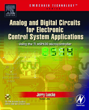
Analog Electronics Laboratory Manual - 10ESL37Experiment No : 5DATE :BJT DARLINGTON EMITTER FOLLOWERAIM:To design and test a Darlington emitter follower circuit with and withoutboot strapping and determine the gain, input and output impedance.COMPONENTS REQUIRED:Sl. storsDCSupply,CROAC millivoltmeterSpecificationQtySL1002 Nos.10 f1 No0.47µf2 Nos.1 M , 2.2 M , 1.5 K , 10 K , 47K withProbe,SignalEach 1 Nogenerator,THEORY:Normally transistors are used as amplifiers. But there are some applicationsin which, matching of impedance is required between two circuits without any gainor attenuation. In such applications emitter followers are used. Emitter followershave large input impedance and small output impedance. Darlington emitterfollower has two transistors connected in cascade such that the emitter of firsttransistor is connected to the base of second transistor. The voltage gain of thedarlington emitter follower is close to unity. The major drawback of this circuit isthat the second transistor amplifies leakage current of the first transistor andoverall leakage current becomes high. The output is observed at the emitterterminal of the second transistor. Hence it is called an emitter follower.Dept of ECE- GCEMPage 27
Analog Electronics Laboratory Manual - 10ESL37CIRCUIT DIAGRAM:Darlington emitter follower without bootstrappingVcc 12VR11MCb 0.47µfQ1QSL100SL100R22.2 MVinCE 0.47µfRE1.5 KVoDarlington emitter follower with bootstrappingDESIGN:Given IC 4mA, VCC 12V, VBE 0.6V, 1 2 100To find RE:Applying KVL to the output loop of the second transistor, we getVCC VCE VRETherefore VRE VCC – VCE 12 – 6Therefore VRE 6VW.K.T RE VRE / IE2Here IE2 IC2Therefore RE 6 / 4 x 10⁻³RE 1.5k Dept of ECE- GCEMPage 28
Analog Electronics Laboratory Manual - 10ESL37To find R1 & R2:From the circuit we haveVA VBE1 VBE2 VRE 0.6 0.6 6 7.2VW.K.T. IC IBTherefore IB (4 x 10⁻³)/ 100 40 ALet 10IB be the current through R1 and 9IB be the current through R2.From the fig. we see thatR1 (VCC – VA) / 10IBTherefore R1 12K From the fig. R2 VA / 9IBTherefore R2 20 K 22K W.K.T. CC 10 / XRE 10 / ( 2. .f.RE)Assume f 50HzTherefore CC 21.2 F 47 FW.K.T. Cb 10 / XRB 10 / ( 2. .f.RB )where RB R1 R2 7.5k Therefore Cb 4.2 F 4.7 FChose R3 10 K , CB 10µf for bootstrappingPROCEDURE:1.2.3.4.5.Rig up the circuit as shown in the fig.Check the circuit for biasing, i.e. check VCE, VCC and VRE.Give a sinusoidal input signal of 1KHz from a signal generator.Set the input signal to a value such that the output doesn‟t get clipped.For different frequencies of the input signal, read the output on thevoltmeter and verify that the gain is 1.6. To measure input impedance, connect a resistor of 47k in series withthe signal generator.7. Measure the voltage at the input point (VS) and at the point after theresistor (VIN).8. Current through the resistor is given by the expressionI (VS - VIN) / 47K.9. Input impedance is given by ZIN VIN / 47 K10.To measure output impedance, connect a DRB in parallel with theoutput.11.Adjust all the knobs of the DRB to maximum.12.Start reducing the resistance in the DRB from a large value until theoutput reduces to half.13.The resistance in the DRB is the output impedance.Dept of ECE- GCEMPage 29
Analog Electronics Laboratory Manual - 10ESL37TABULAR COLUMN:VIN constantFrequency(Hz)V0 (V)AVAV (dB)WAVEFORM:VinVin0tV00tVinRESULT :Dept of ECE- GCEMPage 30
Analog Electronics Laboratory Manual - 10ESL37Experiment No : 6DATE :HARTLEY OSCILLATOR / COLPITT’S OSCILLATORAIM:Design a
Develop the ability to analyze and design analog electronic circuits using discrete components. Observe the amplitude and frequency responses of common amplification circuits. Design, construct, and take measurement of various analog circuits to compare experime