Transcription
ANALOG COMMUNICATION SYSTEMSByDr. S. MUNI RATHNAMProfessor & H.O.DDEPT. of E.C.EVEMU IT, CHITTOOR
JAWAHARLAL NEHRU TECHNOLOGICAL UNIVERSITY ANANTAPURII B.Tech II-Sem (E.C.E)T Tu C313(15A04402) ANALOG COMMUNICATION SYSTEMSUNIT- I: Introduction: Elements of communication systems,Information, Messages and Signals, Modulation, Modulation Methods,Modulation Benefits and Applications.Amplitude Modulation & Demodulation: Baseband and carriercommunication, Amplitude Modulation (AM), Rectifier detector,Envelope detector, Double sideband suppressed carrier (DSB-SC)modulation & its demodulation, Switching modulators, Ringmodulator, Balanced modulator, Frequency mixer, sideband and carrierpower of AM, Generation of AM signals, Quadrature amplitudemodulation (QAM), Single sideband (SSB) transmission, Time domainrepresentation of SSB signals & their demodulation schemes (withcarrier, and suppressed carrier), Generation of SSB signals, Vestigialsideband (VSB) modulator & demodulator, Illustrative Problems.
UNIT- IIAngle Modulation &Demodulation: Concept of instantaneous frequency, Generalizedconcept of angle modulation, Bandwidth of angle modulated waves – Narrow bandfrequency modulation (NBFM); and Wide band FM (WBFM), Phase modulation,Verification of Frequency modulation bandwidth relationship, Features of anglemodulation, Generation of FM waves – Indirect method, Direct generation;Demodulation of FM, Bandpass limiter, Practical frequency demodulators, Small erroranalysis, Pre-emphasis, & De-emphasis filters, FM receiver, FM Capture Effect,.Carrier Acquisition- phased locked loop (PLL), Costas loop, Frequency divisionmultiplexing (FDM), and Super-heterodyne AM receiver, Illustrative Problems.UNIT- IIINoise in Communication Systems: Types of noise, Time domain representation ofnarrowband noise, Filtered white noise, Quadrature representation of narrowbandnoise, Envelope of narrowband noise plus sine wave, Signal to noise ratio & probabilityof error, Noise equivalent bandwidth, Effective noise temperature, and Noise figure,Baseband systems with channel noise, Performance analysis (i.e. finding SNRexpression) of AM, DSB-SC, SSB-SC, FM, PM in the presence of noise, IllustrativeProblems.UNIT- IVAnalog pulse modulation schemes: Pulse amplitude modulation – Natural sampling,flat top sampling and Pulse amplitude modulation (PAM) & demodulation, Pulse-TimeModulation – Pulse Duration and Pulse Position modulations, and demodulationschemes, PPM spectral analysis, Illustrative Problems.Radio Receiver measurements: Sensitivity, Selectivity, and fidelity.
UNIT- VInformation & Channel Capacity: Introduction, Information content of message,Entropy, Entropy of symbols in long independent and dependent sequences, Entropyand information rate of Markoff sources, Shannon’s encoding algorithm, Discretecommunication channels, Rate of information over a discrete channel, Capacity ofdiscrete memoryless channels, Discrete channels with memory, Shannon – Hartleytheorem and its implications, Illustrative problems.Text books:1. B. P. Lathi, “Modern Digital and Analog Communication Systems,” Oxford Univ.press, 3rd Edition, 2006.2. Sham Shanmugam, “Digital and Analog Communication Systems”, Wiley-Indiaedition, 2006.3. A. Bruce Carlson, & Paul B. Crilly, “Communication Systems – An Introduction toSignals & Noise in Electrical Communication”, McGraw-Hill International Edition, 5thEdition, 2010.References:1. Simon Haykin, “Communication Systems”, Wiley-India edition, 3rd edition, 2010.2. Herbert Taub& Donald L Schilling, “Principles of Communication Systems”, TataMcGraw-Hill, 3rd Edition, 2009.3. R.E. Ziemer& W.H. Tranter, “Principles of Communication-Systems Modulation &Noise”, Jaico Publishing House, 2001.4. George Kennedy and Bernard Davis, “Electronics & Communication System”,TMH, 2004.
IntroductionElements of Communication System:Communication: It is the process of conveying ortransferring information from one point toanother.(Or)It is the process of establishing connection or linkbetween two points for information exchange.
Elements of Communication System:Information source:The message or information to be communicatedoriginates in information source.Message can be words, group of words, code, data,symbols, signals etc.Transmitter :The objective of the transmitter block is to collectthe incoming message signal and modify it in asuitable fashion (if needed), such that, it can betransmitted via the chosen channel to thereceiving point.
Elements of Communication System:Channel :Channel is the physical medium which connects thetransmitter with that of the receiver.The physical medium includes copper wire, coaxialcable, fibre optic cable, wave guide and freespace or atmosphere.Receiver:The receiver block receives the incoming modifiedversion of the message signal from the channeland processes it to recreate the original (nonelectrical) form of the message signal.
Signal, Message, InformationSignal:It is a physical quantity which varies with respect totime or space or independent or dependentvariable.(Or)It is electrical waveform which carries information.Ex: m(t) Acos(ωt ϕ)Where, A Amplitude or peak amplitude(Volts)w Frequency ( rad/sec)ϕ Phase (rad)
Types of Signals Analog or Continuous Signal Digital SignalAnalog or Continuous Signal: If the amplitude ofsignal continuously varies with respect to time orif the signal contains infinite number ofamplitudes, it is called Analog or continuoussignal.
Types of SignalsDigital Signal: If the signal contains only twodiscrete amplitudes, then it is called digital signal. With respect to communication, signals areclassified into, Baseband signal Bandpass signalBaseband signal: If the signal contains zerofrequency or near to zero frequency, it is calledbaseband signal.Ex: Voice, Audio, Video, Bio-medical signals etc.
Types of SignalsBandpass signal: If the signal contains band offrequencies far away from base or zero, it is calledbandpass signal.Ex: AM, FM signals.Message: It is sequence of symbols.Ex: Happy New Year 2020.Information: The content in the message is calledinformation. It is inversely proportional toprobability of occurrence of the symbol. Information is measured in bits, decits, nats.
Limitations of Communication System Technological Problems:To implement communication systems, Tx, Rx, ion system is expensive and complex. Bandwidth & Noise:The effect of noise can be reduced byprovidingmore bandwidth to stations but due to this lessnumber of stations can only be accommodated. Signal to Noise Ratio (SNR):Noise should be low toincrease channel capacity but it is an unavoidableaspect of communication system.
ModulationIt is the process of varying the characteristics ofhigh frequency carrier in accordance withinstantaneous values of modulating or messageor baseband signal.(Or)It is a frequency translation technique whichconverts baseband or low frequency signal tobandpass or high frequency signal.Modulation is used in the transmitter.
Types of Modulation
Types of Modulation Amplitude Modulation: Amplitude of the carrieris varied in accordance with the instantaneousvalues of modulating signal. Frequency Modulation: Frequency of the carrieris varied in accordance with the instantaneousvalues of modulating signal. Phase Modulation: Phase of the carrier is variedin accordance with the instantaneous values ofmodulating signal.
Benefits or Need of Modulation To reduce the length or height of antenna For multiplexing For narrow banding or to use antenna with singleor same length To reduce noise effect To avoid equipment limitation or to reduce thesize of the equipment.
Amplitude ModulationThe amplitude of the carrier signal varies inaccordance with the instantaneous amplitude ofthe modulating signal.
Amplitude ModulationThe carrier signal is given by,C(t) Ac CoswctWhere, Ac Maximum amplitude of the carriersignal.W 2πfc Frequency of the carrier signal.Modulating or baseband signal is given by,X(t) Am CoswmtWhere, Am Amplitude of the baseband signal.
Amplitude ModulationThe standard equation for amplitude modulatedsignal is expressed as,S(t) Ac Cos2πfct[1 ma(Cos2πfmt)]Where, ma Am/Ac Modulation IndexTime Domain representation of AM:S(t) AcCos2πfct μAc/2Cos[2πfc 2πfm]t μAc/2Cos[2πfc-2πfm]tI term: Carrier signal with amplitude Ac and frequency fc.II term: Amplitude μAc/2, frequency fc fm , Upper sidebandfrequencyIII term: Amplitude μAc/2, frequency fc-fm , Lower sidebandfrequency
Amplitude ModulationFrequency Domain representation of AM:The time domain representation of AM wave isgiven by,S(t) Ac Cos2πfct[1 ma(Cos2πfmt)]Taking Fourier transform on both sides,S(f) Ac/2[δ(f-fc) δ(f fc)] Acma/2[M(f-fc) M(f fc)]
Modulation IndexModulation index or depth of modulation is givenby,ma [Amax-Amin/ Amax Amin] Am/AcPercentage of modulation index is,%ma [Amax-Amin/ Amax Amin]X100 [Am/Ac ]X100Types of AM with respect to modulation index: Under Modulation (ma 1) Critical Modulation (ma 1) Over Modulation (ma 1)
Types of AM
Generation of AM WaveSquare Law modulator:This circuit consists of, A non-linear device Band pass filter Carrier source and modulating signal
Generation of AM WaveThe modulating signal and carrier are connected inseries with each other and their sum V1(t) isapplied at the input of non-linear device such asdiode or transistor.V1(t) x(t) Ac cosWct --- (1)The input-output relation of non-linear device is,V2(t) aV1(t) b V12(t) --- (2)Using (1) in (2),V2(t) a x(t) a Ac Cos (2πfct) bx2(t) 2bx(t) Ac Cos (2πfct) b Ac2 Cos2(2πfct)---(3)Out of these 5 terms, 1,3,5 terms are unuseful termsare eliminated by BPF.
Generation of AM WaveOutput of BPF is given by,V0(t) a Ac Cos (2πfct) 2bx(t) Ac Cos (2πfct)---(4)Switching Modulator:
Generation of AM WaveThe carrier signal c(t) is connected in series withmodulating signal x(t).Sum of these two signals is passed through a diode.Output of the diode is passed through a band passfilter and the result is an AM wave.V1(t) x(t) c(t) ---(1)Amplitude of c(t) is much greater than x(t), so ON &OFF of diode is determined by c(t)When c(t) is positive, V2(t) V1(t) ---(2)When c(t) is negative, V2(t) 0 ---(3), Finally,V2(t)
Detection of AM WaveDemodulation or detection is the process ofrecovering the original message signal from thereceived modulated signal.Types of AM Detectors:1. Square Law detector2. Envelope detector3. Rectifier detector
Detection of AM WaveSquare Law detector:The amplitude modulated wave is given as input to thesquare law device.V2(t) aV1(t) b V12(t)---(1)When this is passed through square law device,V2(t) aAcCoswct aAcmx(t)Coswct bAc2Cos2wct 2bAc2mx(t)Cos2wct bAc2m2x2(t)Cos2wct---(2)
Detection of AM WaveIn order to extract the original message signal, V2(t)is passed through a low pass filter .The output of LPF is,V0(t) mbAc2x(t) ---(3)Envelope Detector:
Detection of AM Wave The standard AM wave is applied at the input ofdetector . In every positive half cycle of input, diode isforward biased which charges capacitor ‘C’. When capacitor charges to peak value of inputvoltage, diode stops conducting. The capacitor discharges through ‘R’ betweenpositive peaks. This process continuous and capacitor chargesand discharges repeatedly.
Detection of AM WaveRectifier detector:
Detection of AM Wave In rectifier detector, diode acts as rectifier whichallows only positive half of the modulated signalto the filter. The low pass filter removes all the high frequencycomponents giving envelope at its output. This envelope will have some dc value which canbe removed by passing through capacitor ‘C’. The output of rectifier detector is the envelopewith zero dc value.
Double Sideband-Suppressed Carrier(DSB-SC)The equation of AM wave in simple form is givenby,S(t) Ac Cos wct Here, carrier component remains constant anddoes not convey any information.Therefore, if the carrier is suppressed, onlysidebands remain in the spectrum requiring lesspower. DSB-SC Contains two side bands i.e USB & LSB Power efficiency is 100% % Power saving in DSB-SC w.r.t AM is 66.67%.
DSB-SC ModulationA DSB-SC signal is obtained by multiplying themodulating signal x(t) with carrier signal c(t).So, we need a product modulator for thegeneration of DSB-SC wave.
DSB-SC Modulation1. Balanced Modulator:It consists of two amplitude modulators arrangedin balanced configuration to suppress thecarrier completely.
DSB-SC ModulationOperation: Carrier c(t) is applied to both the modulators. Message signal x(t) is applied directly tomodulator 1 and with a phase shift of 1800 tomodulator 2.Output of modulator 1 is,S1(t) Ac[1 mx(t)] cos 2πfct ---(1)Output of modulator 2 is,S2(t) Ac[1- mx(t)] cos 2πfct ---(2)These two outputs are applied to subtractor,whose output is, 2mAcx(t) cos 2πfct---(3)
DSB-SC ModulationRing Modulator:It operates in two modes Mode1: Without modulating signal x(t) Mode 2: With modulating signal x(t)Mode1: c(t) is positive Diodes D1, D2 forward biased, D3,D4 Reverse biased Output of ring modulator will be zero.C(t) is negative Diodes D1, D2 reverse biased, D3,D4 forward biased Output of ring modulator will be zero.Mode2: When modulating signal is present, during positive half cycle D1,D2 will be ON and secondary of T1 is directly applied to primary ofT2. Output will be positive During negative half cycle of modulating signal D3, D4 will be ONproducing positive voltage.2.
DSB-SC Modulation
Time Domain representation of DSB-SCMessage signal is given by,x(t) Am cos(2πfmt) ---(1)Carrier signal is given by,C(t) Ac cos(2πfct) ---(2)DSB-SC modulated signal is given by,S(t) x(t) c(t) ---(3)S(t) 1/2AmAc[cos2π(fc fm)t cos2π(fc-fm)t]--(4)
Frequency Domain representation of DSB-SCThe frequency spectrum of DSB-SC is obtained bytaking Fourier transform of s(t)S(f) F{[1/2AmAc[cos2π(fc fm)t cos2π(fc-fm)t]}S(f) This is the spectrum of DSB-SC wave.
Demodulation of DSB-SCCoherent Detection:The modulating signal x(t) is recovered from DSBSC wave s(t) by multiplying it with a locallygenerated carrier and then passing through aLPF.
Demodulation of DSB-SCV(t) s(t) c(t) ---(1)Where,S(t) 1/2AmAc[cos2π(fc fm)t cos2π(fc-fm)t]—(2)C(t) cos2πfct ---(3)Substituting (2) & (3) in (1)When this is passed through a LPF,V0(t)
Single Sideband-Suppressed Carrier(SSB-SC)The modulation process in which only one side bandis transmitted and with carrier suppression iscalled Single sideband suppressed carrier (SSBSC).Modulating Signal m(t) Am Cos (2πfmt) and CarrierSignal c(t) Ac Cos (2πfct)SSB-SC signal can be generated by passing DSB-SCsignal through BPF. And DSB-SC signal isgenerated by multiplying m(t) & c(t).ASSB-SC(t) Cos2π( )t (or)ASSB-SC(t) Cos2π( )t
Generation of SSB-SC1. Filter or Frequency Discrimination Method:Filter method of generating DSB-SC Signal requiresproduct modulator and BPF as shown in figure.Here Product Modulator generates DSB-SC Signalwhich contains two side bands i.e USB & LSB.By passing DSB-SC Signal through BPF either ofsidebands are removed for generating SSB-SCSignal.
Generation of SSB-SC2.Phase Shift or Phase Discrimination Method:The figure shows the block diagram for the phaseshift method of SSB generation and this system isused for the suppression of lower sideband.This system uses two Product modulatorsM1 and M2 and two 90o phase shifting networks.
Vestigial Sideband Transmission VSB-SC is used to transmit Video Signal which is largeBW signal containing very low and very highfrequency components. Very low Frequencies raise sidebands near to carrierfrequency. It is not possible to suppress one complete sideband. Very low frequencies contain most of usefulinformation, any effect to complete suppress the onesideband would result phase distortion at thesefrequencies. Therefore compromise has been made to suppressthe part of sideband. Hence VSB-SC Signal containone full sideband & part of other side band.
VSB Modulation & DemodulationModulation:Modulating signal x(t) and carrier signal c(t) areapplied as inputs to the product modulator.S(t) x(t)c(t)This is the DSB-SC wave. It is applied to a side bandfilter which passes the wanted sidebandcompletely and vestige of unwanted sideband.
VSB Modulation & DemodulationDemodulation:The demodulation of VSB signal can be achievedusing a coherent detector by multiplying s(t) witha locally generated carrier.V(t) s(t)AcCos2πfctThis signal is then passed through a LPF whichpasses low frequency message signal and rejectscarrier.
Quadrature Amplitude Modulation(QAM)QAM is used to transmit color information in TVsignal transmission.
Quadrature Amplitude Modulation(QAM)The output of Transmitter S (t) m1 (t) Cos (2πfct m2 (t) Sin (2πfct)The output of multiplier S1(t) [m1 (t) Cos (2πfct m2 (t) Sin (2πfct)] xCos (2πfct) m1(t) Cos2(2πfct) m2(t) sin(2πfct) Cos(2πfct) m1(t)/2(1 Cos4πfct)) m2(t)/2 Sin(4πfct) m1(t)/2 m1(t)/2 Cos(4πfct) m2(t)/2 Sin(4πfct)Second and Third terms are high frequency signals are eliminated byLPF. So that output of LPF is m1(t)/2The output of multiplier S2(t) [m1 (t) Cos (2πfct m2 (t) Sin (2πfct)] xSin (2πfct) m2(t)/2Sin(4πfct) m2(t)/2-m2(t)/2Cos(4πfct)First and Third terms are high frequency signals are eliminated by LPF.So that output of LPF is m2(t)/2 .
Super Heterodyne AM ReceiverHeterodyne means mixing two frequencies andgenerating single or constant frequency and theoutput of mixer will be fixed frequency.Specification of AM Receiver: The frequency range of AM-MW( Medium wave): (540-1640) KHz Band width of receiver:1640 KHz – 540 KHz 1100 KHz Band width of each AM station : 10 KHz No. of stations available: 110 Intermediate frequency (fIF): 455 KHz
Super Heterodyne AM Receiver
Super Heterodyne AM ReceiverAntenna: It is passive device which converts electromagnetic signal intoelectrical signal.RF Tuned Amplifier: It is broad band amplifier which contain tuning circuit and amplifier. Tuning circuit designed to select 110 stations and amplifier providesamplification for 1100 KHz band width. RF tuned amplifier is responsible for sensitivity, selectivity, Image signalrejection and noise reduction.Mixer: It is combination of frequency mixer and Band Pass Filter (BPF). Frequency generates sum and difference frequency of incoming signaland locally generated signal. BPF selects difference frequency at the output whose center frequency isequal to 455 KHz.Local Oscillator: It is either Colpits or Hartley oscillator. It generates carrier frequency 455 KHz greater than the incoming carrierfrequency to produce constant or fixed frequency.
Super Heterodyne AM ReceiverIF Amplifier: It is narrow band, high gain and fixed frequency amplifier which providesamplification for 10 KHz band width at center frequency of 455 KHz. It is cascade CE amplifier which provides 90% of total receiveramplification.Detector or Demodulator: It is frequency translator circuit which extracts modulating signal fromAM signal. Usually Envelope detector is used. Fidelity of the receiver is mainly depends on detector or demodulator.Audio Amplifier: It is low frequency amplifier which provides amplification at (20- 20K) Hz. It contain cascade CE Voltage amplifier followed by Power amplifier.Loud Speaker: It converts Electrical signal into sound or audio signal.
ANGLE MODULATIONAngle modulation is a process of varying angle of thecarrier in accordance with the instantaneous values ofmodulating signal.Angle can be varied by varying frequency or phase.Angle modulation is of 2 types. Frequency Modulation Phase Modulation
Frequency ModulationThe process of varying frequency of the carrier inaccordance with the instantaneous values of themodulating signal.Relation between angle and frequency :Consider carrier signal c(t) Ac Cos (wct φ) Ac Cos (2πfct φ)Where, Wc Carrier frequencyφ PhaseC(t) Ac Cos[ψ(t)], where, ψ(t) wct φi.e Frequency can be obtained by derivating angle andangle can be obtained by integrating frequency.
Frequency ModulationFrequency modulator converts input voltage intofrequency i.e the amplitude of modulating signal m(t)changes to frequency at the output.Consider carrier signal c(t) Ac CoswctThe frequency variation at the output is calledinstantaneous frequency and is expressed as,wi wc kf m(t)Where, kf frequency sensitivity factor in Hz/volt
Frequency ModulationThe angle of the carrier after modulation can bewritten as,Frequency modulated signal can be written as,AFM(t) Ac Cos [ψi(t)] Ac Cos [wct kfʃm(t)dt]Frequency Deviation in FM:The instantaneous frequency, wi wc kf m(t) wc ΔwWhere, Δw kf m(t) is called frequency deviation whichmay be positive or negative depending on the sign ofm(t).
Phase ModulationThe process of varying the phase of carrier in accordancewith instantaneous values of the modulating signal.Consider modulating signal x(t) and carrier signal c(t) Ac CoswctPhase modulating signal,APM(t) Ac Cos[ ψi(t)]Where, ψi(t) wct kpm(t)Where, kp Phase sensitivity factor in rad/voltAPM(t) Ac Cos[wct kpm(t)]
Phase ModulationFrequency deviation in PM:Conversion between Frequency and Phase Modulation:
Modulation IndexDefinition:Modulation Index is defined as the ratio of frequencydeviation ( ) to the modulating frequency (fm).M.I. Frequency DeviationModulating Frequencymf δfmIn FM M.I. 1Modulation Index of FM decides (i)Bandwidth of the FM wave.(ii)Number of sidebands in FM wave.
Deviation RatioThe modulation index corresponding to maximum deviationand maximum modulating frequency is called deviation ratio.Deviation Ratio Maximum DeviationMaximum modulating Frequency δmaxfmaxIn FM broadcasting the maximum value of deviation is limited to 75kHz. The maximum modulating frequency is also limited to 15 kHz.
Percentage M.I. of FMThe percentage modulation is defined as the ratio of theactual frequency deviation produced by the modulating signalto the maximum allowable frequency deviation.% M.I Actual deviationMaximum allowable deviation
Mathematical Representation of FM(i) Modulating Signal:It may be represented as,em Em cos mt (1)Here cos term taken for simplicitywhere,em Instantaneous amplitude m Angular velocity 2 fmfm Modulating frequency
(ii) Carrier Signal:Carrier may be represented as,ec Ec sin ( ct )-----(2)where,ec cfc Instantaneous amplitudeAngular velocity2 fcCarrier frequencyPhase angle
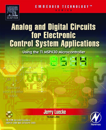
(iii) FM Wave:Fig. Frequency Vs. Time in FMFM is nothing but a deviation of frequency.From Fig. 2.25, it is seen that instantaneous frequency ‘f’ of the FMwave is given by,f fc (1 K Em cos mt) (3)where,fc Unmodulated carrier frequencyK Proportionality constantEm cos mt Instantaneous modulating signal(Cosine term preferred for simplicity otherwise wecan use sine term also) The maximum deviation for this particular signal will occur, whencos mt 1 i.e. maximum. Equation (2.26) becomes,f fc (1 K Em) (4) f fc K Emfc (5)
So that maximum deviation will be given by, K Emfc (6)The instantaneous amplitude of FM signal is given by,eFM A sin [f( c, m)] A sin (7)where,f( c, m) Some function of carrier and modulatingfrequenciesLet us write equation (2.26) in terms of as, c (1 K Em cos mt)To find , must be integrated with respect to time.Thus, dt c (1 K Em cos mt) dt c (1 K Em cos mt) dt c (t KEm sin mt) m ct KEm c sin mt m ct KEmfc sin mt m
ct sin mt[. K Em fc]fm Substitute value of in equation (7)Thus,eFM A sin ( ct sin mt )---(8)fmeFM A sin ( ct mf sin mt )---(9)This is the equation of FM.
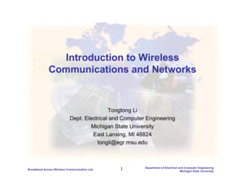
Frequency Spectrum of FMFrequency spectrum is a graph of amplitude versus frequency.The frequency spectrum of FM wave tells us about number ofsideband present in the FM wave and their amplitudes.The expression for FM wave is not simple. It is complex because itis sine of sine function.Only solution is to use ‘Bessels Function’.Equation (2.32) may be expanded as,eFM {A J0 (mf ) sin ct J1 (mf ) [sin ( c m) t sin ( c m) t] J1 (mf ) [sin ( c 2 m) t sin ( c 2 m) t] J3 (mf ) [sin ( c 3 m) t sin ( c 3 m) t] J4 (mf ) [sin ( c 4 m) t sin ( c 4 m) t] } (2.33)From this equation it is seen that the FM wave consists of:(i)Carrier (First term in equation).(ii)Infinite number of sidebands (All terms except first term aresidebands).The amplitudes of carrier and sidebands depend on ‘J’ coefficient. c 2 fc, m 2 fmSo in place of c and m, we can use fc and fm.
Fig. : Ideal Frequency Spectrum of FM
Bandwidth of FMFrom frequency spectrum of FM wave shown in Fig.2.26, we can say that the bandwidth of FM wave isinfinite.But practically, it is calculated based on how manysidebands have significant amplitudes.(i)The Simple Method to calculate the bandwidth is BW 2fmx Number of significant sidebands--(1)With increase in modulation index, the number ofsignificant sidebands increases. So that bandwidth alsoincreases.(ii)The second method to calculate bandwidth is byCarson’s rule.
Carson’s rule states that, the bandwidth of FM wave is twicethe sum of deviation and highest modulating frequency.BW 2( fmmax) (2)Highest order side band To be found from table 2.1 after thecalculation of modulation Index m where, m /fme.g. If m 20KHZ/5KHZFrom table, for modulation index 4, highest order side band is 7th.Therefore, the bandwidth isB.W. 2 fm Highest order side band 2 5 kHz 7 70 kHz
Types of Frequency ModulationFM (Frequency Modulation)Narrowband FM(NBFM)[When modulation index is small]Wideband FM(WBFM)[When modulation index is large]
Comparison between Narrowbandand Wideband onRange th6.Applications2.3.4.NBFMWBFMLess than or slightlygreater than 15 kHzGreater than 120 Hz to 3 kHz20 Hz to 15 kHzSlightly greater than 15 to 2500Small approximatelysame as that of AMBW 2fm75 kHzLarge about 15 timesgreater than that ofNBFM.BW 2( fmmax)FM mobile communication Entertainmentlike police wireless,broadcasting (can be usedambulance, short rangefor high quality musicship to shoretransmission)communication etc.
Representation of FMFM can be represented by two ways:1. Time domain.2. Frequency domain.1.FM in Time DomainTime domain representation means continuous variation of voltage with respectto time as shown in Fig. .Fig. 1 FM in Time Domain2.FM in Frequency Domain Frequency domain is also known as frequency spectrum. FM in frequency domain means graph or plot of amplitude versus frequency asshown in Fig. 2.29.Fig. 2: FM in Frequency Domain
Pre-emphasis and De-emphasisPre and de-emphasis circuits are used only in frequency modulation. Pre-emphasis is used at transmitter and de-emphasis at receiver.1. Pre-emphasis In FM, the noise has a greater effect on the higher modulating frequencies. This effect can be reduced by increasing the value of modulation index (mf ), forhigher modulating frequencies. This can be done by increasing the deviation ‘ ’ and ‘ ’ can be increased byincreasing the amplitude of modulating signal at higher frequencies.Definition:The artificial boosting of higher audio modulating frequencies inaccordance with prearranged response curve is called pre-emphasis. Pre-emphasis circuit is a high pass filter as shown in Fig.
As shown in Fig. 1, AF is passed through a high-pass filter, beforeapplying to FM modulator. As modulating frequency (fm) increases, capacitivereactance decreases and modulating voltage goes on increasing.fm Voltage of modulating signal applied to FM modulatBoosting is done according to pre-arranged curve as shownin Fig. 2.Fig. 2: P re-emphasis Curve
The time constant of pre-emphasis is at 50 s in all CCIR standards. In systems employing American FM and TV standards, networks havingtime constant of 75 sec are used. The pre-emphasis is used at FM transmitter as shown in Fig.Fig. FM Transmitter with Pre-emphasis
De-emphasis De-emphasis circuit is used at FM receiver.Definition:The artificial boosting of higher modulating frequencies in theprocess of pre-emphasis is nullified at receiver by process calledde-emphasis. De-emphasis circuit is a low pass filter shown in Fig.Fig. De-emphasis Circuit
Fig. De-emphasis CurveAs shown in Fig.5, de-modulated FM is applied to the de-emphasiscircuit (low pass filter) where with increase in fm, capacitive reactance Xcdecreases. So that output of de-emphasis circuit also reduces Fig. 5 shows the de-emphasis curve corresponding to a timeconstant50 s. A 50 s de-emphasis corresponds to a frequency response curvethat is 3 dB down at frequency given by,f 1/ 2πRC 1/ 2π x 50x 1000 3180 Hz
Comparison between Pre-emphasisand De-emphasisParameter1. Circuit usedPre-emphasisHigh pass filter.De-emphasisLow pass filter.2. Circuit diagram3. Response curveFig. 2.36Fig. 2.37Fig. 2.38Fig. 2.394. Time constantT RC 50 sT RC 50 s5. DefinitionBoosting of higherfrequenciesRemoval of higherfrequencies6. Used atFM transmitterFM receiver.
Comparison between AM and FMParameterAM1. DefinitionAmplitude of carrier isvaried in accordance withamplitude of modulatingsignal keeping frequencyand phase constant.2. ConstantparametersFrequency and phase.FMFrequency of carrier isvaried in accordance withthe amplitude ofmodulating signal keepingamplitude and phaseconstant.Amplitude and phase.3. Modulated signal4. Modulation Indexm Em/Ecm / fm5. Number ofsidebandsOnly twoInfinite and depends on mf.6. BandwidthBW 2fmBW 2 ( fm (max))7. ApplicationMW, SW band bro
Lathi, “ModernDigital and Analog Communication Systems,”Oxford Univ. press, 3rd Edition, 2006. 2. Sham Shanmugam, “Digitaland Analog Communication Systems”,Wiley-India . Digital Signal Analog or Continuous Signal: If the amplitude of signal continuously varies with respect