Transcription
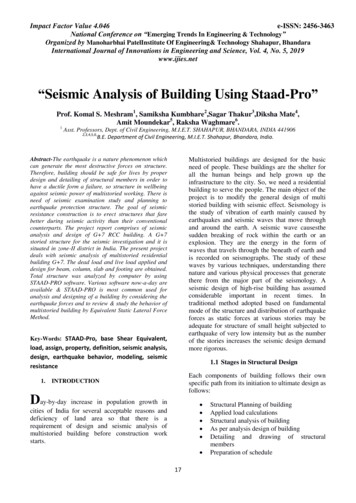
International Journal of Scientific & Engineering Research Volume 8, Issue 6, June-2017ISSN 2229-5518243Seismic Analysis of Prefabricated Structuresusing ETABSMohamed Muneer I P1, Vishnu Varthan H2, Fawas Abdul Azeez3Abstract:This Thesis is about the comparative study of the analysis using software E-TABS and process of rehabilitating a shake table for use inseismic analysis of small-scale models in the School of Architecture. Lab view 8.0 Student Edition was used to write the controllingprogram for the shake table. Initially the frame was analyzed using the E-TABS Software.In order to test seismic response of a prototype building, a 7-story reinforced concrete building was modeled in piano wire and plywoodand tested on the shake table. The shake table recorded data from an accelerometer mounted on the model. The model was built tohave the same resonant frequency as the prototype building.Keywords: Shake Table, Labview 8.0, Seismic Analysis, Teaching Tool, Seismic Modeling.—————————— ——————————1. INDRODUCTIONSeismology is the scientific study of earthquakes and thepropagation of elastic waves through the Earth or throughother planet-like bodies. The field also includes studiesof earthquake environmental effects such as tsunamis aswell as diverse seismic sources such as volcanic, tectonic,oceanic, atmospheric, and artificial processes such asexplosions. A related field that uses geology to inferinformationregardingpastearthquakesis paleoseismology. A recording of earth motion as a function oftime is called a seismogram. A seismologist is a scientistwho does research in seismology.manually and using ETABS software separately. In thiscase, a 22.5m x 22.5m, 8 storey structure is modeled usingETABS software. The height of each storey is taken as3meter making the total height of the structure 24 meter.Analysis of the structure is done and then the resultsgenerated by this software are compared with manualanalysis of the structure using IS 1893:2002.IJSER2. LITERATURE REVIEWIn the early work of Harrison [1], an equilateral triangularspace steel frame subjected to proportional loads wastested. Yarimci [2] tested a full-size two-dimensional,twobay, three-story steel frame in which all members werebent about the strong axis. Wakabayashi and Matsui [3]tested two two-dimensional, one-bay, one- and two-storysteel frames of quarter-scale subjected to proportionalloads. Kanchanalai [4] tested a two-dimensional, two-bay,two-story steel frame of large scale to verify his plastic-zoneanalysis technique. Avery and Mahendran [5,6] performedlarge-scale testing of a two dimensional, one-bay, one-storysteel frame comprising noncompact sections subjected toproportional loads. Recently, Kim and Kang [7] and Kim etal. [8] performed some ultimate strength large-scale testingfor three-dimensional, onebay, two-story steel framessubjected to non-proportional and proportional loads,respectively. Kim and Kang [9] performed an ultimatestrength large-scale testing to account for local buckling ofa three-dimensional, one-bay, two-story steel frame.3.STUCTURAL ANALYSIS BY E-TABSETABS is the present day leading design software in themarket. Many design use this software companies for theirproject design purpose. So, this paper mainly deals with thecomparative analysis of the results obtained from theanalysis of a multi storey building structure when analyzed4.PROBLEM DEFINITIONA 22.5m x 22.5 m, 8 storey multi storey regularstructure is considered for the study. Storey height is 3m.Modeling and analysis of the structure is done on ETABSsoftware.Preliminary DataTABLE 4.1 Preliminary DataLengthxWidthNo. of StoreyBeamColumnsSlab thicknessSupport ConditionThickness External WallGrade of Concrete and steelLength of each bay22.5m x 22.5m8 (G 7)250 mm x 400 mm400 mm x 500 mm150 mmFixed120mmM20 and Fe4157.5m4.1 Loading ConsiderationLoads acting on the structure are dead load (DL), LiveLoad(IL) and Earthquake Load (EL) DL: Self weight of thestructure, Floor load and Wall loadsLL: Live load 3KN/m2 is consideredSeismic: Zone: IIIZone Factor: 0.16Soil type: IIResponse reduction factor: R 3Importance factor: 1Damping: 5%Time period: 0.427 sec (calculated as per IS 1893: 2002)IJSER 2017http://www.ijser.org
International Journal of Scientific & Engineering Research Volume 8, Issue 6, June-2017ISSN 2229-5518244Fig.4.3 Assigning Frame SectionsFig.4.4 Assigning Material PropertiesFig.4.1 Plan of the structureIJSERFig.4.5 Assigning Section PropertiesFig.4.2 Assigning Frame SectionsDead Load (D. L.) per floorTABLE 4.2 Dead Load CalulationItemsBeamColumnSlabWallSize (LBH)m30.25 x 0.4 x0.750.5 x 0.4 x7.522.5 x 22.5x 0.1522.5 x 1822.5420648Fig.4.6 Procedure to model slabUM3132.94.2. UDL due to wall:Wall is not modulated only UDL is due to wall on beam isconsidered.IJSER 2017http://www.ijser.org
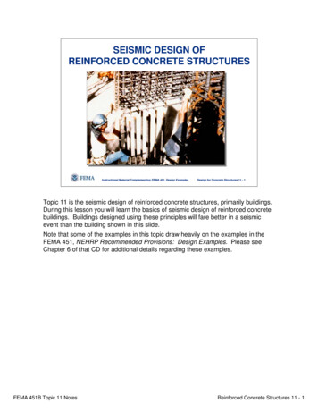
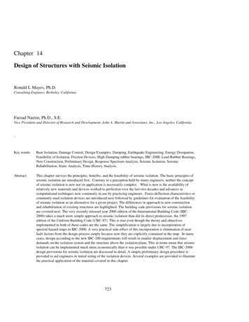
International Journal of Scientific & Engineering Research Volume 8, Issue 6, June-2017ISSN 2229-5518Fig.4.7 Procedure to assign UDL to beamUDL OF WALL 0.12(thickness) 3(height of wall) 20(Brick density) 7.2 kN/m4.3 . Live load on floor area245Fig 6: 7.2kN/m UDL applied to beam on each floor LiveLoad becomes DL 25% LL.DL 3132.9, 25% LL 379.687DL 25% LL 3572.5875 kN per each floor.This live load reduction is defined by a command masssource in ETABS 7.1.As mentioned in II.C, Live load is considered 3kN/m2 oneach floor.Each floor has dimension 22.5m x 22.5m.Live load on each floor is3x22.5x22.5 1518.75 KNAs per IS 1893:2002 (pg no. 24) Clause no. 7.3.1, Tableno.8,Only 25% live load is considered in seismic weightcalculations.25% of live load 0.25x 1518.75 379.6875 KN.Fig.4.11 Procedure to define Mass SourceIJSERFig.4.8 7.2kN/m UDL applied to beam on each floorFig.4.12 Actual Mass Source window in ETABS andAxial load in each columnFig.4.9 Procedure to assign live load on floor4.4. Seismic weight calculation of buildingAs per III, CW1 W2 W3 W4 W5 W6 W7 3512.5875 kN. Lumpedmass at roof floor.In the calculation of seismic weight, for the terrace floor50% of the weight is considered for walls and columns.W8 432 (230.4 / 2) 1822.5 (648 / 2) 2693.7 kN.Total weight (W) (3512.587 x 7) 2693.7 27281.8125kN.Now the seismic weight obtain in ETABS software is asshown below.Fig.4.10 Applied live load on each floorAs per IS 1893:2000, the load combination Dead load Fig.4.13 Procedure to display axial loads inIJSER 2017http://www.ijser.org
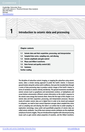
International Journal of Scientific & Engineering Research Volume 8, Issue 6, June-2017ISSN 2229-5518246columnsNow the algebraic sum of all the axial forces gives seismicweight of the complete building. The same values can beobtained in the table form and facility of exporting thesevalues in excel is available in ETABS that algebraic sumand other any mathematical calculations can be simplifiedin excel. The procedure of exporting these values in ETABSis explained as below in four steps.Fig.4.14 Base Shear in each StoreyIJSER5. ANALYSIS FOR BASE SHEARA. Design Seismic Base ShearAs per IS 1893:2002, Page No. 24, The totaldesign lateral force or design seismic base Shear (VB)along any principal direction shall be determined by thefollowing expression:VB Ah x wWhere,Ah Design horizontal acceleration spectrumValue as perClause 6.4.2, using the fundamental natural periodT, as perClause 7.6 in the considered direction of vibration,andw Seismic weight of the building as per Clause7.4.2. As per IS 1893:2002, Clause 6.4.2, Page No. 14,Where,Z 0.16, As per IS 1893:2002, Table No.2 andANNEX E, Zone Factor for IIIrd zone.I 1, As per IS 1893:2002, Table No.6, Importancefactor, It is depends on the functional use of the structure.R 3, As per IS 1893:2002, Table No.7, Responsereduction factor.Sa/g Average response acceleration coefficient.The value of average response accelerationcoefficient is determined from the graph given on pageno.16 of IS 1893:2002.Fig.4.15 Seismic on coefficient, it is required to calculate timeperiod.As per IS 1893:2002, Page No.7, time period T isgiven byH Height of the building in meter. 24 mNote: As per IS 1893:2002 for the terrace floor, halfof the total load is considered for walls and columns. Sowhile modeling in ETABS, top story height is modeled 1.5mwhile height of other stories is 3m. So in ETABS model H 22.5m d Base dimension of the building in meter 22.4 mTa 0.455 sec.Ta 0.427 sec.(In case of ETABS)Sa/g 2.5.Now Design horizontal acceleration spectrumValue cans be calculated.Fig 17: Window of ETABS base shear value Vb(1797.28 kN) in ETABS. (Ref.6)B. Vertical Distribution of Base Shear to DifferentFloor Levels:The design base shear VB shall be distributed longthe height of the building as per following equationNow base shearVB Ah x w 0.0667 x 27281.8125VB 1819.696 kN.IJSER 2017http://www.ijser.org
International Journal of Scientific & Engineering Research Volume 8, Issue 6, June-2017ISSN 2229-5518Fig.4.16 Window of ETABS base shear value5.1. Vertical Distribution of Base Shear to DifferentFloor Levels:The design base shear V B shall be distributed long theheight of the building as per following equationIJSERWhere,Qi Design lateral force at floor i,Wi Seismic weight of floor i,hi Height of floor i measured from baseFloorWi hi2HeightQ(KN)9.624BaseShear in KN1331613.2926126453.15 38.51810.0739284519.59 86.621771.57412 505812.6515 790332.19 240.61530.97618 1138078.3 346.461290.377211549051 471.57943.91824 1551571.2 472.345977431.9472.34153.981819.691684.95n Number of stories in the building is the number of levelsat which the masses are located.IJSER 2017http://www.ijser.org247
Seismic Analysis of Prefabricated Structures using ETABS . . In order to test seismic response of a prototype building, a 7story reinforced concrete building was modeled in piano wire and plywood - . design lateral force or design seismic base Shear (VB) along any principal direction sha