Transcription
Seismic DesignManualVolume IIBuilding Design Examples:Light Frame, Masonry and Tilt-upApril 2000
CopyrightCopyright 2000 Structural Engineers Association of California. All rights reserved.This publication or any part thereof must not be reproduced in any form without thewritten permission of the Structural Engineers Association of California.PublisherStructural Engineers Association of California (SEAOC)1730 I Street, Suite 240Sacramento, California 95814-3017Telephone: (916) 447-1198; Fax: (916) 443-8065E-mail: info@seaoc.org; Web address: www.seaoc.orgThe Structural Engineers Association of California (SEAOC) is a professionalassociation of four regional member organizations (Central California, NorthernCalifornia, San Diego, and Southern California). SEAOC represents the structuralengineering community in California. This document is published in keeping withSEAOC’s stated mission: “to advance the structural engineering profession, toprovide the public with structures of dependable performance through the applicationof state-of-the-art structural engineering principles; to assist the public in obtainingprofessional structural engineering services; to promote natural hazard mitigation; toprovide continuing education and encourage research; to provide structural engineerswith the most current information and tools to improve their practice; and to maintainthe honor and dignity of the profession.”EditorGail H. Shea, Albany, CaliforniaDisclaimerPractice documents produced by the Structural Engineers Association ofCalifornia (SEAOC) and/or its member organizations are published as part ofour association’s educational program. While the information presented in thisdocument is believed to be correct, neither SEAOC nor its memberorganizations, committees, writers, editors, or individuals who have contributedto this publication make any warranty, expressed or implied, or assume anylegal liability or responsibility for the use, application of, and/or reference toopinions, findings, conclusions, or recommendations included in thispublication. The material presented in this publication should not be used forany specific application without competent examination and verification of itsaccuracy, suitability, and applicability by qualified professionals. Users ofinformation from this publication assume all liability arising from such use.iiSEAOC Seismic Design Manual, Vol. II (1997 UBC)
Table of ContentsTable of ContentsPreface. vAcknowledgments . viiSuggestions for Improvement . ixIntroduction . 1How to Use This Document . 2Notation. 3References . 10Design Example 1Wood Light Frame Residence. 11Design Example 2Wood Light Frame Three-Story Structure . 87Design Example 3Cold-Formed Steel Light Frame Three-Story Structure . 159Design Example 4Masonry Shear Wall Building . 213Design Example 5Tilt-Up Building . 247Design Example 6Tilt-Up Wall Panel With Openings . 289SEAOC Seismic Design Manual, Vol. II (1997 UBC)iii
Table of ContentsivSEAOC Seismic Design Manual, Vol. II (1997 UBC)
PrefacePrefaceThis document is the second volume of the three-volume SEAOC Seismic Design Manual.The first volume, “Code Application Examples,” was published in April 1999. Thesedocuments have been developed by the Structural Engineers Association of California(SEAOC) with funding provided by SEAOC. Their purpose is to provide guidance on theinterpretation and use of the seismic requirements in the 1997 Uniform Building Code(UBC), published by the International Conference of Building Officials (ICBO), andSEAOC’s 1999 Recommended Lateral Force Requirements and Commentary (also called theBlue Book).The Seismic Design Manual was developed to fill a void that exists between the Commentaryof the Blue Book, which explains the basis for the UBC seismic provisions, and everydaystructural engineering design practice. While the Manual illustrates how the provisions of thecode are used, the examples shown do not necessarily illustrate the only appropriate methodsof seismic design, and the document is not intended to establish a minimum standard of care.Engineering judgment needs to be exercised when applying these examples to real projects.Volume I: Code Application Examples, provides step-by-step examples of how to useindividual code provisions, such as how to compute base shear or building period. Volumes IIand III: Design Examples, furnish examples of the seismic design of common types ofbuildings. In Volumes II and III, important aspects of whole buildings are designed to show,calculation-by-calculation, how the various seismic requirements of the code areimplemented in a realistic design.Volume II contains six examples. These illustrate the seismic design of the followingstructures: (1) a two-story wood light frame residence, (2) a three-story wood light framebuilding, (3) a three-story cold formed light frame building, (4) a one-story masonry buildingwith panelized wood roof, (5) a one-story tilt-up building with panelized wood roof, and (6)the design of a tilt-up wall panel with large openings.Work on the final volume, Building Design Examples, Volume III—Steel, Concrete andCladding, is nearing completion and is scheduled for release in late Spring 2000.It is SEAOC’s present intention to update the Seismic Design Manual with each edition ofthe building code used in California. Work is currently underway on a 2000 InternationalBuilding Code version.Ronald P. GallagherProject ManagerSEAOC Seismic Design Manual, Vol. II (1997 UBC)v
PrefaceviSEAOC Seismic Design Manual, Vol. II (1997 UBC)
AcknowledgmentsAcknowledgmentsAuthorsThe Seismic Design Manual was written by a group of highly qualified structuralengineers. These individuals are both California registered civil and structuralengineers and SEAOC members. They were selected by a Steering Committee setup by the SEAOC Board of Directors and were chosen for their knowledge andexperience with structural engineering practice and seismic design. TheConsultants for Volumes I, II and III are:Ronald P. Gallagher, Project ManagerRobert ClarkDavid A. HutchinsonJon P. KilandJohn W. LawsonJoseph R. MaffeiDouglas S. ThompsonTheodore C. ZsuttyVolume II was written principally by Douglas S. Thompson (Examples 1, 2,and 3), Jon P. Kiland (Example 4), Ronald P. Gallagher (Example 5), and JohnW. Lawson (Example 6). Many useful ideas and helpful suggestions wereoffered by the other Consultants. Consultant work on Volume III is currentlyunderway.Steering CommitteeOverseeing the development of the Seismic Design Manual and the work of theConsultants was the Project Steering Committee. The Steering Committee wasmade up of senior members of SEAOC who are both practicing structuralengineers and have been active in Association leadership. Members of the SteeringCommittee attended meetings and took an active role in shaping and reviewing thedocument. The Steering Committee consisted of:John G. Shipp, ChairRobert N. ChittendenStephen K. HarrisMartin W. JohnsonScott A. StedmanSEAOC Seismic Design Manual, Vol. II (1997 UBC)vii
AcknowledgmentsReviewersA number of SEAOC members, and other structural engineers, helped check theexamples in this volume. During its development, drafts of the examples were sentto these individuals. Their help was sought in both review of code interpretations aswell as detailed checking of the numerical computations. The assistance of thefollowing individuals is gratefully acknowledged:Ricardo ArevaloGary AustinRobert ChittendenKelly CobeenMichael CochranSusan DowtyGerald FreemanStephen K. HarrisGary HoJohn LawsonDilip M. KhatriHarry (Hank) Martin (AISC)David McCormickGary MochizukiWilliam NelsonNeil PetersonMichael RileyGeorge RichardsAlan Robinson (for CMACN)John Rose (APA)Douglas ThompsonJerry TuckerCraig WilcoxDennis WishSeismology CommitteeClose collaboration with the SEAOC Seismology Committee was maintainedduring the development of the document. The 1999-2000 Committee reviewed thedocument and provided many helpful comments and suggestions. Their assistanceis gratefully acknowledged.1999-2000Martin W. Johnson, ChairSaif Hussain, Past ChairDavid BonowitzRobert N. ChittendenTom H. HaleStephen K. HarrisDouglas C. HohbachY. Henry HuangSaiful IslamH. John KhadiviJaiteeerth B. KinhalRobert LyonsSimin NaasehChris V. TokasMichael Riley, Assistant to the ChairviiiSEAOC Seismic Design Manual, Vol. II (1997 UBC)
Suggestions for ImprovementSuggestions for ImprovementIn keeping with two of its Mission Statements: (1) “to advance the structuralengineering profession” and (2) “to provide structural engineers with the mostcurrent information and tools to improve their practice”, SEAOC plans to updatethis document as seismic requirements change and new research and betterunderstanding of building performance in earthquakes becomes available.Comments and suggestions for improvements are welcome and should be sent tothe following:Structural Engineers Association of California (SEAOC)Attention: Executive Director1730 I Street, Suite 240Sacramento, California 95814-3017Telephone: (916) 447-1198Fax: (916) 443-8065E-mail: info@seaoc.orgWeb address: http://www.seaoc.orgErrata NotificationSEAOC has made a substantial effort to ensure that the information in thisdocument is accurate. In the event that corrections or clarifications are needed,these will be posted on the SEAOC web site at http://www.seaoc.org or on theICBO website at http://ww.icbo.org. SEAOC, at its sole discretion, may or may notissue written errata.SEAOC Seismic Design Manual, Vol. II (1997 UBC)ix
Seismic DesignManualVolume IIBuilding Design Examples:Light Frame, Masonry and Tilt-up
IntroductionIntroductionSeismic design of new light frame, masonry and tilt-up buildings for therequirements of the 1997 Uniform Building Code (UBC) is illustrated in thisdocument. Six examples are shown: (1) a two-story wood frame residence, (2)a large three-story wood frame building, (3) a three-story cold formed steellight frame building, (4) a one-story masonry (concrete block) building withpanelized wood roof, (5) a one-story tilt-up building with panelized wood roof,and (6) the design of a tilt-up wall panel with large openings.The buildings selected are for the most part representative of construction typesfound in Zones 3 and 4, particularly California and the Western States. Designshave been largely taken from real world buildings, although somesimplifications were necessary for purposes of illustrating significant points andnot presenting repetive or unnecessarily complicated aspects of a design.The examples are not complete building designs, or even complete seismicdesigns, but rather they are examples of the significant seismic design aspectsof a particular type of building.In developing these examples, SEAOC has endeavored to illustrate correct useof the minimum provisions of the code. The document is intended to help thereader understand and correctly use the design provisions of UBC Chapters 16(Design Requirements), 19 (Concrete), 21 (Masonry), 22 (Steel) and 23(Wood). Design practices of an individual structural engineer or office, whichmay result in a more seismic-resistant design than required by the minimumrequirements of UBC, are not given. When appropriate, however, theseconsiderations are discussed as alternatives.In some examples, the performance characteristics of the structural system arediscussed. This typically includes a brief review of the past earthquakebehavior and mention of design improvements added to recent codes. SEAOCbelieves it is essential that structural engineers not only know how to correctlyinterpret and apply the provisions of the code, but that they also understandtheir basis. For this reason, many examples have commentary included on pastearthquake performance.While the Seismic Design Manual is based on the 1997 UBC, references aremade to the provisions of SEAOC’s 1999 Recommended Lateral ForceProvisions and Commentary (Blue Book). When differences between the UBCand Blue Book are significant, these are brought to the attention of the reader.SEAOC Seismic Design Manual, Vol. II (1997 UBC)1
How to Use This DocumentHow to Use This DocumentGenerally, each design example is presented in the following format. First,there is an “Overview” of the example. This is a description of the building tobe designed. This is followed by an “Outline” indicating the tasks or steps tobe illustrated in each example. Next, “Given Information” provides the basicdesign information, including plans and sketches given as the starting point forthe design. This is followed by “Calculations and Discussion”, which providesthe solution to the example. Some examples have a subsequent sectiondesignated “Commentary” The commentary is intended to provide a betterunderstanding of aspects of the example and/or to offer guidance to the readeron use of the information generated in the example. Finally, references andsuggested reading are given under “References.” Some examples also have a“Forward” and/or section “Factors Influencing Design” that provide remarks onsalient points about the design.Because the document is based on the UBC, UBC notation is used throughout.However, notation from other codes is also used. In general, reference to UBCsections and formulas is abbreviated. For example, “1997 UBC Section1630.2.2” is given as §1630.2.2 with 1997 UBC (Volume 2) being understood.“Formula (32-2)” is designated Equation (32-2) or just (32-2) in the right-handmargins of the examples. Similarly, the phrase “Table 16-O” is understood tobe 1997 UBC Table 16-O. Throughout the document, reference to specificcode provisions, tables, and equations (the UBC calls the latter formulas) isgiven in the right-hand margin under the heading Code Reference.When the document makes reference to other codes and standards, this isgenerally done in abbreviated form. Generally, reference documents areidentified in the right-hand margin. Some examples of abbreviated referencesare shown below.Right-Hand Margin NotationMore Complete Description23.223, Vol. 3Section 23.223 of Volume 3, of the 1997 UniformBuilding Code (UBC).Section E3.3 of the 1996 Edition of the American Ironand Steel Institute (AISI) Specification for the Designof Cold-Formed Steel Structural Members.Table 5A of the 1991 National Design Specificationfor Wood Construction (NDS).Table 1-A of Ninth Edition, American Institute ofSteel Construction (AISC) Manual of SteelConstruction, Allowable Stress Design.96 AISI E3.391 NDS Table 5ATable 1-A, AISC-ASD2SEAOC Seismic Design Manual, Vol. II (1997 UBC)
NotationNotationThe following notations are used in this document. These are generally consistentwith that used in the UBC and other codes such as ACI, AISC, AISI and NDS.Some additional notations have also been added. The reader is cautioned that thesame notation may be used more than once and may carry entirely differentmeaning in different situations. For example, E can mean the tabulated elasticmodulus under the NDS definition (wood) or it can mean the earthquake loadunder §1630.1 of the UBC (loads). When the same notation is used in two or moredefinitions, each definition is prefaced with a brief description in parentheses (e.g.,wood or loads) before the definition is given.A (wood diaphragm) area of chord cross section, in squareinchesA (wood shear wall) area of boundary element cross section,in square inches (vertical member at shear wall boundary)AB ground floor area of structure in square feet to include areacovered by all overhangs and projections.Ac the combined effective area, in square feet, of the shearwalls in the first story of the structure.Ae the minimum cross-sectional area in any horizontal plane inthe first story, in square feet of a shear wall.Ap the effective area (in square inches) of the projection of anassumed concrete failure surface upon the surface fromwhich the anchor protrudes.As area of tension reinforcing steelAse equivalent area of tension reinforcing steelAx the torsional amplification factor at Level x.Aconc net concrete section areaa depth of equivalent rectangular stress blockap numerical coefficient specified in §1632 and set forth inTable 16-O of UBC.SEAOC Seismic Design Manual, Vol. II (1997 UBC)3
Notation4Btn nominal tensile strength of anchor bolt in masonry, inpounds.b (concrete beam) width of compression face of memberb (wood diaphragm) diaphragm width, in feetb (wood shear wall) wall width, in feetbtu factored tensile force supported by anchor bolt in masonry,in poundsCa seismic coefficient, as set forth in Table 16-Q of UBC.Cd penetration depth factorCD load duration factorCM wet service factorCt numerical coefficient given in §1630.2.2 of UBC.Cv seismic coefficient, as set forth in Table 16-R of UBC.c distance from neutral axis to extreme fiberD (loads) dead load on a structural element.D (wood) diameterDe the length, in feet, of a shear wall in the first story in thedirection parallel to the applied forces.d (wood) dimension of wood member (assembly)d (concrete or masonry) distance from extreme compressionfiber to centroid of tension reinforcementd (loads) distance from lateral resisting element to the centerof rigidityd (wood) pennyweight of nail or spikeda deflection due to anchorage details in wood shear wall(rotation and slip at tie-down bolts), in inchesSEAOC Seismic Design Manual, Vol. II (1997 UBC)
NotationE (wood diaphragm) elastic modulus of chords, in psiE (wood shear wall) elastic modulus of boundary element(vertical member at shear wall boundary), in psiEc modulus of elasticity of concrete, in psiEm modulus of elasticity of masonry, in psiE, E ' (wood) tabulated and allowable modulus of elasticity, in psie diaphragm eccentricityen nail deformation in inches (see Table 23-2-K of UBC)E, Eh, Em, Ev, (loads) earthquake loads set forth in §1630.1 of UBC.Fb ' Fb ' tabulated and allowable bending design value, in psiFc ' Fc ' tabulated and allowable compression design value perpendicular tograin, in psiFv ' Fv ' tabulated and allowable compression shear design value parallel tograin (horizontal shear), in psiFx design seismic force applied to Level i, n or x, respectively.Fp design seismic force on a part of the structure.Fpx design seismic force on a diaphragm.Ft (loads) that portion of the base shear, V, consideredconcentrated at the top of the structure in addition to Fn.Ft torsional shear forceFv direct shear forceFy specified yield strength of structural steel.fb extreme fiber bending stressfc (wood) actual compression stress parallel to grainSEAOC Seismic Design Manual, Vol. II (1997 UBC)5
Notationfc ' f c fi lateral force at Level i for use in Formula (30-10) of UBC. specified compressive strength of masonry, in psifp equivalent uniform load.fr (masonry) modulus of rupture, in psify specified tension yield strength of reinforcing steel.fv (wood) actual shear stress parallel to grainG modulus of rigidity of plywood, in pounds per square inch(see Table 23-2-J of UBC)g acceleration due to gravity.h (concrete) height of wall between points of support, ininchesh (wood shear wall) wall height, in feetfm 'hi, hn, hx6specified compressive strength of concrete.(wood) actual compression stress perpendicular to grain height in feet above the base to level i, n or x, respectivelyI importance factor given in Table 16-K of UBC.Icr moment of inertia of cracked concrete or masonry sectionIg moment of inertia of gross concrete or masonry sectionabout centroidal axis, neglecting reinforcementIp importance factor specified in Table 16-K of UBC.k (wood) wall stiffnessL (loads) live load on a structural element, except roof liveloadLr (loads) roof live loadSEAOC Seismic Design Manual, Vol. II (1997 UBC)
NotationL (wood) span length of bending memberL (wood diaphragm) diaphragm length, in feetlc (concrete) vertical distance between wall supports, ininchesLevel i level of the structure referred to by the subscript i. “i 1”designates the first level above the base.Level n that level that is uppermost in the main portion of thestructure.Level x that level that is under design consideration. “x 1”designates the first level above the base.M maximum bending momentMcr nominal cracking moment strength in concrete or masonryMn nominal moment strengthMs the maximum moment in the wall resulting from theapplication of the unfactored load combinationsMu factored moment at sectionM.C. moisture content based on oven-dry weight of wood, inpercentNa near-source factor used in the determination of Ca inSeismic Zone 4 related to both the proximity of thebuilding or structure to known faults with magnitudes andslip rates as set forth in Tables 16-S and 16-U of UBC.Nv near-source factor used in the determination of Cv inSeismic Zone 4 related to both the proximity of thebuilding or structure to known faults with magnitudes andslip rates as set forth in Tables 16-T and 16-U of UBC.P total concentrated load or total axial loadPc (concrete) design tensile strength of anchors, in poundsPu factored axial loadSEAOC Seismic Design Manual, Vol. II (1997 UBC)7
NotationR numerical coefficient representative of the inherentoverstrength and global ductility capacity of lateral-forceresisting systems, as set forth in Table 16-N or 16-P ofUBC.r a ratio used in determining ρ. See §1630.1 of UBC.SA, SB, SC, SD, SE, SF 8soil profile types as set forth in Table 16-J of UBC.T elastic fundamental period of vibration, in seconds, of thestructure in the direction under consideration.T (loads) torsional momentt thicknesst (plywood) effective thickness of plywood for shear, ininches (see Tables 23-2-H and 23-2-I of UBC)tm thickness of main memberts thickness of side memberV (wood) shear force.V (loads) the total design lateral force or shear at the basegiven by Formula (30-5), (30-6), (30-7) or (30-11) of UBC.Vm nominal shear strength of masonryVn (concrete or masonry) nominal shear strengthVn (wood) fastener load, in poundsVs nominal shear strength of shear reinforcementVu (masonry) required shear strengthVx the design story shear in Story x.v (wood diaphragm) maximum shear due to design loads inthe direction under consideration, plfv (wood shear wall) maximum shear due to design loads atthe top of the wall, in plfSEAOC Seismic Design Manual, Vol. II (1997 UBC)
NotationW (wood) total uniform load.W (loads) the total seismic dead load defined in §1630.1.1 of UBC.wi, wx that portion of W located at or assigned to Level i or x,respectively.Wp the weight of an element or component.wpx the weight of the diaphragm and the element tributarythereto at Level x, including applicable portions of otherloads defined in §1630.1.1 of UBC.x, y distance to centroidZ seismic zone factor as given in Table 16-I of UBC.Z, Z' (wood) nominal and allowable lateral design value for asingle fastener connection. (wood) the calculated deflection of wood diaphragm orshear wall, in inches. M maximum inelastic response displacement, which is thetotal drift or total story drift that occurs when the structureis subjected to the design basis ground motion, includingestimated elastic and inelastic contributions to the totaldeformation defined in §1630.9 of UBC. S design level response displacement, which is the total driftor total story drift that occurs when the structure issubjected to the design seismic forces. cr deflection at M cr n deflection at M n s (concrete) deflection at M s u deflection due to factored loads, in inches.γ load/slip modulus for a connection, in pounds per inch.δi horizontal displacement at Level i relative to the base dueto applied lateral forces, f, for use in Formula (30-10) ofUBC.SEAOC Seismic Design Manual, Vol. II (1997 UBC)9
Notationφ strength-reduction factorρ (loads) redundancy/reliability factor given by Formula (30-3) ofUBC.ρ (concrete and masonry) ratio of area of flexural tensilereinforcement, As , to area bd.ρb reinforcement ratio producing balanced strain conditions.Ωo seismic force amplification factor, which is required toaccount for structural overstrength and set forth in Table16-N of UBC. ( c X ) sum of individual chord-splice slip values on both sides ofwood diaphragm, each multiplied by its distance to thenearest support.ReferencesThe following codes and standards are referenced in this document. Otherreference documents are indicated at the end of each Design Example.ACI-318, 1995, American Concrete Institute, Building Code Regulations forReinforced Concrete, Farmington Hills, MichiganAISC, American Institute of Steel Construction, Manual of Steel Construction,Allowable Stress Design-ASD, Chicago, IllinoisAISI, 1996, American Iron and Steel Institute, Specification for the Design ofCold-Formed Steel Structural Members, Washington, D.CNDS, 1991, American Forest & Paper Association, National Design Specificationfor Wood Construction, Washington, D.C.UBC 1997, International Conference of Building Officials, Uniform BuildingCode. Whittier, California.SEAOC Blue Book, 1999, Recommended Lateral Force Requirements andCommentary. Structural Engineers Association of California, Sacramento,California.10SEAOC Seismic Design Manual, Vol. II (1997 UBC)
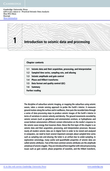
Design Example 1 n Wood Light Frame Residence'HVLJQ ([DPSOH :RRG /LJKW )UDPH 5HVLGHQFHFigure 1-1. Wood light frame residence)RUHZRUGSmall wood frame residences, such as the one in this example, have traditionallybeen designed using simplified design assumptions and procedures based largelyon judgment and precedent. This example illustrates the strict, literal application ofthe 1997 UBC provisions. Two of the requirements shown, while required by thecode, are considerably different than current California practice:1. The use of wood diaphragms as part of the lateral force resisting system.Traditionally, light frame dwellings have been designed assuming that suchdiaphragms behave as infinitely flexible elements. This assumption simplifiesthe analysis and allows lateral forces to be distributed to the vertical elements ofthe lateral force resisting system by tributary area methods. The code has had adefinition of a flexible diaphragm since the 1988 UBC (§1630.6 of the 1997SEAOC Seismic Design Manual, Vol. II (1997 UBC)
Design Example 1 n Wood Light Frame ResidenceUBC). UBC §1630.6 permits diaphragms to be treated as flexible, only if themaximum deflection of the diaphragm under the lateral loading is equal to orgreater than twice the deflection of the vertical elements supporting thediaphragm in the story below. In this example, the diaphragm has beendetermined not to meet these criteria, and the design is based on the rigiddiaphragm assumption. However, recognizing that the diaphragms in thisstructure likely behave as semi-rigid elements, neither fully flexible nor fullyrigid, in this example an envelope approach has been used in which twoanalyses are performed. The first analysis uses the traditional flexiblediaphragm assumptions and the second analysis is based on rigid diaphragmassumptions. The lateral resisting elements have been designed for the mostsevere forces produced by either assumption. Refer to the overview portion ofthis design example for further discussion about using the envelope approach.Although these examples are a literal application of the 1997 UBC, the SEAOCCode and Seismology committees are of the joint opinion that the use of themore traditional design approach can provide acceptable lift-safety performancefor most one- and two-family dwellings. The commentary below provides morediscussion of these issues:2.The use of a system with limited ductility specifically cantilevered columns.In this example, the cantilevered columns are used to provide lateral resistanceat the garage door openings. In conventional practice, these would be designedfor forces calculated using the R value associated with that system (R 2.2),with the balance of the structure designed with an R value with light framedshear walls (R 5.5). UBC §1630.4.4 requires that the R value used in eachdirection, may not be greater than the least value for any of the systems used inthat same direction. Therefore, in this design example, because the R value forthe cantilevered columns at the garage has an R value of 2.2, the entire structurein this direction has been designed using this R value.Rigid versus flexible diaphragm assumptions.Small, light frame detached one- and two-family dwellings have traditionally beendesigned using flexible diaphragm assumptions, or by a “hybrid” approach oftreating closely spaced walls as a unit (i.e., as rigidly connected) and treating theremaining diaphragm as flexible. Also, light frame detached one- and two-familydwellings have been built with the conventional construction provisions of th
SEAOC Seismic Design Manual, Vol. II (1997 UBC) v Preface This document is the second volume of the three-volume SEAOC Seismic Design Manual. The first volume, “Code Application Examples,” was published in April 1999. These documents have been developed by the Structural Engineers Assoc