Transcription
BADGERINDUSTRIESTABLE OF CONTENTSwww.NUSIG.comSales@NUSIG.com2019 EditionGENERAL NOTES: -------------------------------- (4 - 7)BADGER INDUSTRIES SEISMIC HARDWARE CAPACITY DETAILS: --------------- (9 - 14)ANVIL Fig: 212 & Fig: 212FP PIPE CLAMP SEISMIC CAPACITY DETAILS: --- (16 - 23)ROD STIFFENER INSTALLATION DETAILS:ALL TRADES - Single Hanger, Trapeze, HVAC Duct & Equipment Type Hangers - (25 - 27)RIGID BRACING INSTALLATION DETAILS:ALL TRADES - EMT Conduit Rigid Brace Arm Member Options -----------------------SINGLE HANGER - Mechanical / Electrical / Plumbing / Fire Protection ---------------TRAPEZE HANGER - Mechanical / Electrical / Plumbing / Fire Protection ------------HVAC DUCT -------------------------------------EQUIPMENT ---------------------------------------(29 - 31)(32 - 40)(41 & 42)(43 - 46)(47 & 48)CABLE BRACING INSTALLATION DETAILS:ALL TRADES - Badger Industries Cable Brace Kit Options -------------------------------SINGLE HANGER - Mechanical / Electrical / Plumbing / Fire Protection ---------------TRAPEZE HANGER - Mechanical / Electrical / Plumbing / Fire Protection ------------HVAC DUCT -------------------------------------EQUIPMENT ---------------------------------------(50)(51 - 53)(54 & 55)(56 - 58)(59 & 60)VIBRATION ISOLATION BRACING INSTALLATION DETAILS:ALL TRADES - Badger Industries Cable Brace Kit Options -------------------------------- (62)SINGLE HANGER - Mechanical / Electrical / Plumbing / Fire Protection ---------------- (63 - 65)EQUIPMENT --------------------------------------- (66 & 67)SEISMIC VERTICAL CONN., TO STRUCTURE INSTALLATION DETAILS:CONCRETE FILLED METAL DECKING -- (69 - 72)CONCRETE SLAB ------------------------------- (73 - 75)STEEL BEAM & JOIST ------------------------- (76 - 90)SEISMIC BRACE CONN., TO STRUCTURE INSTALLATION DETAILS:CONCRETE FILLED METAL DECKING -- (92 - 97)CONCRETE SLAB ------------------------------- (98 - 103)STEEL BEAM & JOIST ------------------------- (104 - 107)
GENERAL NOTES
BADGERINDUSTRIESGENERAL NOTESwww.NUSIG.comSales@NUSIG.com2019 Edition(GN1). Neither NUSIG nor Badger Industries is responsible for engineering or detailing the useof NUSIG, Badger Industries and/or other products and components for a specificproject and/or application. All such engineering is to be performed by an engineer,retained by others, who is licensed to perform the necessary engineering, and who isinsured to provide these ”Responsible Engineer” engineering services. All designsubmittals specifying NUSIG / Badger Industries products and components must besealed and signed by the Responsible Engineer, and submitted for review and approvalto the project S.E.O.R. (Structural Engineer Of Record) and when required, the A.H.J.(Authority Having Jurisdiction).The details, data, information, capacities, etc., within this document are not necessarilyindicative of actual project specific application usage conditions. The usage, design,engineering, installation, inspection, etc., of construction assemblies using NUSIG and/orBadger Industries components shall take into account the limits of the weakest componentsand conditions within the overall assembly, including but not limited to the buildingstructure. Such shall be the responsibility of non NUSIG and/or non Badger Industriesothers.NUSIG / Badger Industries documents are subject to change without notice.LIMITATION OF LIABILITYTo the fullest extent permissible by law, NUSIG, Badger Industries, Anvil International,LLC and, their respective owners, officers, directors, employees, agents and representatives(collective, the “Parties”) excludes all liability except liability that is directly attributableto the willful negligence of the Parties. Should the Parties be held liable, under any theory,the aggregate liability of all of them is limited to the total purchase price of the Partiesproducts that caused the injury or loss. In addition to the foregoing, THE PARTIES AREIN NO EVENT LIABLE FOR ANY LOSS OF BUSINESS OR PROFITS, LOSS OF USE,LOSS OF OPPORTUNITIES, DOWNTIME OR DELAY, LABOR, REPAIR ORMATERIAL COST OR ANY OTHER SIMILAR OR DISSIMILAR, INCIDENTAL ORCONSEQUENTIAL LOSS OR DAMAGE INCURRED BY BUYER. By purchasing theParties products, you agree to this limitation of liability on your behalf, and on behalf ofthe person or organization purchasing the products.WARRANTYNUSIG and/or Badger Industries products are warranted to be free from defects in materialand workmanship at the time of shipment. NO OTHER WARRANTY, WHETHEREXPRESS OR IMPLIED (INCLUDING ANY WARRANTY OF MERCHANTABILITYOR FITNESS FOR A PARTICULAR PURPOSE), SHALL EXIST IN CONNECTIONWITH THE SALE OR USE OF ANY NUSIG AND/OR BADGER INDUSTRIESPRODUCTS. Products claimed to be defective or nonconforming must be identified inwriting and returned (within 30 calendar days) to NUSIG / Badger Industries for inspection.Notice of a warranty claim within this 30 day period is a condition precedent to this Warranty.In no event shall NUSIG / Badger Industries be responsible if the products have beenimproperly stored, improperly used, abused or misused. NUSIG / Badger Industries will,at its option, either repair or replace defective or nonconforming products for which it isresponsible or return the purchase price to the BUYER. THE FOREGOING STATESBUYER’S EXCLUSIVE REMEDY FOR ANY BREACH OF THE NUSIG AND/ORBADGER INDUSTRIES WARRANTY AND FOR ANY CLAIM, WHETHER SOUNDINGIN CONTRACT, TORT OR NEGLIGENCE, FOR LOSS OR INJURY CAUSED BY THESALE OR USE OF ANY NUSIG AND/OR BADGER INDUSTRIES PRODUCT(S).Continued Next Page.
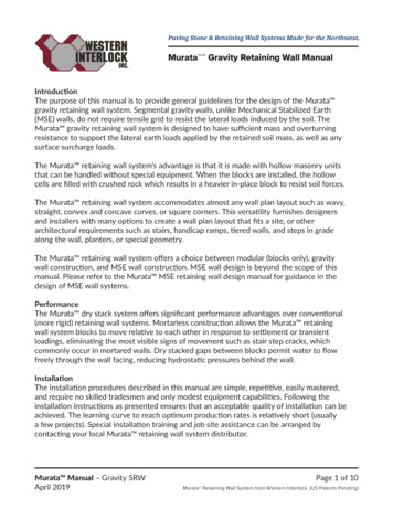
BADGERINDUSTRIESGENERAL NOTESwww.NUSIG.comSales@NUSIG.com2019 Edition(GN1).Continued:ANVIL PRODUCTSAdditional information on Anvil products, including warranties can be found atwww.anvilintl.comWARNINGThe improper use, misuse and/or misapplication of these documents and/or NUSIG /Badger Industries products may cause product malfunction, property damage, bodily injuryand death.(GN2).The project S.E.O.R., shall qualify that the building structure capacity is adequate to handlethe design demand forces. Caution shall be used when reviewing the usability of thisdocument singularly or in combination with other connections / loads / forces / etc., so thatthe building structure and/or other connections are not overloaded or compromised.(GN3).Connections to the building structure and their associated component assemblyconfigurations must account for the standard engineering practices of geometry prying andeccentricity. These can greatly effect the overall capacity of a given anchorage / structureconnection assembly and the accountable design demand point loading to the buildingstructure. All applicable geometry prying and eccentricity shall be accounted by theResponsible Engineer sealing and signing submittals using these documents. See geometryprying example below. Applicable individual components and/or component assembliesmay differ from the depicted example.BA3.375"0.625"Eccentricity @ 45º: e 1.375 - (1.375 * tan45º) 0.00D1.375T X Pcos45º *(e 0.6250.625(Badger SSC 0.707PVX Psin45º 0.707Pinteraction eqn. in terms of P max, T allow & V allow1.375"0.707Tallow(Pmax.)C45º1.2P max (LRFD) 0.707Vallow(LRFD)Equation Accounts For ACI 318 Combined TensionAnd Shear Loads Utilization Check.Continued Next Page.
BADGERINDUSTRIESGENERAL NOTESwww.NUSIG.comSales@NUSIG.com2019 Edition(GN4).Concrete anchors identified within a given detail shall not be substituted. Concreteanchorage spacing coordination requirements for cast-in-place inserts and/or drill-in anchorsand that required for all adjacent anchorages is an all trades / all usage, seismic andnon-seismic design, installation and inspection responsibility that shall be maintained.When installing post installed anchors into non-prestressed reinforced concrete, use careand caution to avoid cutting or damaging reinforcing. When installing anchors intoprestressed concrete, locate the prestressed tendons by using a non-destructive method anddo not cut or damage the tendons during installation.(GN5).Installations that require a specified torque shall be tightened using tools / devices properlycalibrated for such use. Do not over tighten during installation and/or testing. Installationsthat require locking hex nuts can be performed using double back-to-back regular hex nuts.(GN6).Welding shall be performed by a certified welder, and in accordance with the latest editionof the structural welding code of the American Welding Society. After welding check forproper installation tightness / torque on assemblies that were subjected to welding heat.Welds shall use minimum E70xx electrode. Capacitor discharge stud welding shall complywith manufacturer requirements. Welding inspections and testing shall be as required bythe project S.E.O.R.(GN7).Material specifications including but not limited to threaded rods, bolts, hex nuts, couplernuts, etc., and additional project / application specific general notes shall be engineeredand provided by the Responsible Engineer sealing and signing submittals using thesedocuments.(GN8).Selected NUSIG / Badger Industries and Anvil components have been identified as"(No Substitutions)", and the substitution of any such components is not allowed.(GN9).The maximum seismic vertical, seismic transverse and/or seismic longitudinal brace spacingof a given item or trade system shall be as engineered by others. Brace angles referencedwithin this document are measured from vertical, unless indicated otherwise.(GN10). NUSIG / Badger Industries component capacities references.(Fpc) Seismic Vertical Compression, (FpT) Seismic Vertical Tension.(Fp) Seismic Horizontal,(ASD) Gravity Vertical Tension.(ASD)Seismic BraceTo StructureSeismic VerticalTo Structure(Fpc)(FpT)Seismic Vertical MemberGravity VerticalTo StructureSeismic BraceAngle MeasuredFrom VerticalrbeemeMcraicBsmeiS(Fp)Continued Next Page.
BADGERINDUSTRIESGENERAL NOTESwww.NUSIG.comSales@NUSIG.com2019 Edition(GN11). When the seismic vertical components and/or assemblies identified within this documentare used for gravity only and/or combination gravity plus seismic design demand usage,the gravity (ASD) design demand load shall not exceed the identified gravity (ASD)capacity identified within this document.(GN12). A load path for the seismic design demand force shall be maintained. Thus components,including but not limited to, roller hangers, insulation inserts, etc., shall not be used withinthe design and/or assembly of seismic vertical hangers and/or seismic transverse orlongitudinal bracing, unless such components have been seismically tested and/or engineeredby others for such seismic assembly conditions.(GN13).Installer shall clean seismic hardware and trade systemes of dirt, water, oils, greases,lubricants, fluxes, etc., prior to assembly.(GN14). Do not brace to different parts of the building that may act differently during an earthquake,unless bracing and trade system have been designed to account for differential movements.(GN15). Bracing shall not cross through a building seismic joint. When trade systems pass througha building seismic joint, flexibility shall be designed into the trade system to accommodatethe movements (relative displacements as determined by the project S.E.O.R.) of thebuilding seismic joint the trade system is passing through. On each side of the buildingseismic joint the trade system shall be transversely braced within (24") inches of the flexibleportion of the trade system. Bracing shall not be connected to the flexible portions of thetrade system. Said transverse and/or the associated longitudinal bracing for the tradesystem shall be designed to account for the weight and operating forces of the flexible tradesystem. Deviation to the (24") shall be engineered on an application specific basis.(GN16).Construction, inspections, reviews, verifications, maintenance, etc., of any and allitems / designs / conditions / etc., including but not limited to qualification of the buildingstructure, anchorage coordination, non-braced components, brace installations, andcontinued use, repair, replacement and/or abandonment of existing installations beforeand/or after any and all events (seismic or otherwise), etc., is by others.End
BADGER INDUSTRIESSEISMIC HARDWARECAPACITY DETAILS
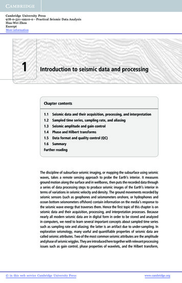
BADGERINDUSTRIESSEISMIC HARDWAREwww.NUSIG.comSales@NUSIG.com2019 Edition BADGER INDUSTRIES [RRK-3/8, RRK-1/2, RRK-5/8, RRK-3/4, RRK-7/8, RRK-1]Seismic Hardware Kits(1/2") Or (5/8")Anchorage Conn., ToBuilding StructureNot Part Of (RRK-X/X) KitBadger Industries(STW-3/8), (STW-1/2), (STW-5/8),(STW-3/4), (STW-7/8) Or (STW-1)Seismic Tabbed Washer Is IncludedWith Each Individual (RRK-X/X) Kit.Badger SSCWSTVerticalRRK-3/8 Kit - Fits (3/8") Dia. Conn.RRK-1/2 Kit - Fits (1/2") Dia. Conn.RRK-5/8 Kit - Fits (5/8") Dia. Conn.RRK-3/4 Kit - Fits (3/4") Dia. Conn.Special Order Required For Sizes,RRK-7/8 Kit - Fits (7/8") Dia. Conn.RRK-1 Kit - iFits (1") Dia. Conn.x/x(TYP.) (2 Of 2)Badger IndustriesProvided Screws ForConn., Of Pivot ArmTo Brace MemberBraceAnglePer Chart(TYP.) (2 Of 2)Badger IndustriesProvided Screws ForConn., Of Pivot ArmTo Brace Memberx/xBadgerSSC-RFHorizontalFpPer ChartBolted / Threaded Conn.,And Hex Nut Not Part Of(RRK-X/X) KitNotice: “SEBO” Seismic Engineering By OthersListed (LRFD) Capacities Based On Seismic Independent Lab TestingPerformed Using Tension And Compression Cyclic Loads PerANSI / FM 1950 - 2016. Also Tested For Unsupported CantileveredConnections. Listed Capacities Do Not Account For Capacity LoadLimits Due To Brace Member Size And Length. Weaker Components/ Conditions Within Overall Design And Application Including, But NotLimited To The Building Structure Capacity Shall Control.Each Individual Badger (SSC-RF) Seismic Bracket Requires (1)Badger (STW), Seismic Tabbed Washer To Be Installed. Sizes (3/4")And Larger Are Not Retrofit. Badger (SSC-RF) Seismic Brackets AreStackable Upon Each Other.Each Individual Badger (SSC) Seismic Bracket Has (1) (1/2") Conn.,Hole And (1) (5/8") Conn., Hole. Badger (SSC) Seismic Brackets AreNot Stackable.BADGER SCC-RFSeismic Hardware EndConnection BracketsCan Be Double, TripleOr QuadrupleStacked BADGER INDUSTRIES Detail (RRK-X/X Kits)Brace Angle From VerticalBADGER INDUSTRIESSeismic HardwareKit NumbersBadgerSSC-RFBadger (SSC)Can Be Welded ToBuilding StructureRRK-3/8, RRK-1/2,RRK-5/8, RRK-3/4,RRK-7/8, RRK-130º to 44º45º to 60º61º to 75º76º to 90ºMaximumFp (LRFD)MaximumFp (LRFD)MaximumFp (LRFD)Fp (LRFD)1,469 lbs.2,018 lbs.1,812 lbs.1,726 lbs.Maximum BADGER INDUSTRIES RRK-X/X KitsRRK-X/X Kits Seismic Hardware - Design Demand Capacity Limits(Elev. View) - (Not To Scale) - (Read General Notes Prior To Use)
BADGERINDUSTRIESSEISMIC HARDWAREwww.NUSIG.comSales@NUSIG.com2019 Edition BADGER INDUSTRIES [SRK]Seismic Hardware Kit1/2SINU GVertical5/8Badger(NUSIG SB1258)Can Be Welded ToBuilding StructureSINU G(SBEMT) Pivot Arm On(NUSIG SB1258) BracketMay Be SubstitutedWith Badger (SVC)Pivot Arm, (TYP.)HorizontalFpPer ChartSB12581/2SB1258SB12585/8SB1258(1/2") Or (5/8")Anchorage Conn., ToBuilding StructureNot Part Of (SRK) Kit(TYP.) (2 Of 2)Badger IndustriesProvided Screws ForConn., Of Pivot ArmTo Brace MemberBraceAnglePer ChartNotice:(TYP.) (2 Of 2)Badger IndustriesProvided Screws ForConn., Of Pivot ArmTo Brace MemberListed (LRFD) Capacities Based On Seismic Independent Lab TestingPerformed Using Tension And Compression Cyclic Loads PerANSI / FM 1950 - 2016 . Also Tested For Unsupported CantileveredConnections. Listed Capacities Do Not Account For Capacity Load LimitsDue To Brace Member Size And Length. Weaker Components / ConditionsWithin Overall Design And Application Including, But Not Limited To TheBuilding Structure Capacity Shall Control.Each Individual Badger (NUSIG SB1258) Seismic Bracket Has (1) (1/2")Conn., Hole And (1) (5/8") Conn., Hole.Pivot Hole In Badger(SBEMT) Pivot Arm Fits (1/2")Diameter Bolt In Anvil Fig: 212Or Fig: 212FP Pipe ClampUsed For Conn., To Pipe BeingBraced. Pipe Clamp Not PartOf (SRK) Kit BADGER INDUSTRIES Detail (SRK Kit)Brace Angle From VerticalBADGER INDUSTRIESSeismic HardwareKit NumberSRK30º to 44º45º to 60º61º to 75ºMaximumMaximumMaximumFp (LRFD)Fp (LRFD)Fp (LRFD)1,174 lbs.1,145 lbs.1,102 lbs. BADGER INDUSTRIES SRK KitSRK Kit Seismic Hardware - Design Demand Capacity Limits(Elev. View) - (Not To Scale) - (Read General Notes Prior To Use)
BADGERINDUSTRIESSEISMIC HARDWAREwww.NUSIG.comSales@NUSIG.com2019 Edition BADGER INDUSTRIES [SRK-MD]Seismic Hardware Kit(1/2") Or (5/8")Anchorage Conn., ToBuilding StructureNot Part Of (SRK-MD) KitVerticalBadger SSCHorizontalFpPer ChartBadger (SSC)Can Be Welded ToBuilding Structure(TYP.) (2 Of 2)Badger IndustriesProvided Screws ForConn., Of Pivot ArmTo Brace MemberBraceAnglePer ChartNotice:(TYP.) (2 Of 2)Badger IndustriesProvided Screws ForConn., Of Pivot ArmTo Brace MemberListed (LRFD) Capacities Based On Seismic Independent Lab TestingPerformed Using Tension And Compression Cyclic Loads PerANSI / FM 1950 - 2016 . Also Tested For Unsupported CantileveredConnections. Listed Capacities Do Not Account For Capacity Load LimitsDue To Brace Member Size And Length. Weaker Components / ConditionsWithin Overall Design And Application Including, But Not Limited To TheBuilding Structure Capacity Shall Control.Each Individual Badger (SSC) Seismic Bracket Has (1) (1/2") Conn., HoleAnd (1) (5/8") Conn., Hole.Pivot Hole In Badger(SBEMT) Pivot Arm Fits (1/2")Diameter Bolt In Anvil Fig: 212Or Fig: 212FP Pipe ClampUsed For Conn., To Pipe BeingBraced. Pipe Clamp Not PartOf (SRK-MD) Kit BADGER INDUSTRIES Detail (SRK-MD Kit)Brace Angle From VerticalBADGER INDUSTRIESSeismic HardwareKit NumberSRK-MD30º to 44º45º to 60º61º to 75ºMaximumFp (LRFD)MaximumFp (LRFD)Fp (LRFD)1,574 lbs.2,380 lbs.2,436 lbs.Maximum BADGER INDUSTRIES SRK-MD KitSRK-MD Kit Seismic Hardware - Design Demand Capacity Limits(Elev. View) - (Not To Scale) - (Read General Notes Prior To Use)
BADGERINDUSTRIESSEISMIC HARDWAREwww.NUSIG.comSales@NUSIG.com2019 Edition BADGER INDUSTRIES [SRK-HD]Seismic Hardware KitWelded ToBuilding StructureBadger SSC(TYP.) (1 Of 2)Badger Industries(SBEMT) Pivot ArmsEach Badger (SSC)Vertical(TYP.) (1 Of 4)Screws EachEnd Conn.(TYP.) (2")EMT ConduitBrace Member(TYP.) (2 Of 4)Badger IndustriesProvided Screws For Conn., OfDouble Pivot Arms To (2") EMTConduit Brace MemberBraceAnglePer Chart(TYP.) (2 Of 4)Badger IndustriesProvided Screws For Conn., OfDouble Pivot Arms To (2") EMTConduit Brace MemberBadger SSCWelded To SteelPipe Or ItemBeing BracedHorizontalFpPer Chart BADGER INDUSTRIES Notice:Detail (SRK-HD Kit)Brace Angle From VerticalBADGER INDUSTRIESSeismic HardwareKit NumberSRK-HD30º to 44º45º to 60º0ºMaximumFp (LRFD)MaximumFp (LRFD)MaximumFp (LRFD)2,626 lbs.3,714 lbs.5,253 lbs.Listed (LRFD) Capacities Based On SeismicIndependent Lab Testing Performed Using Tension AndCompression Cyclic Loads Per ANSI / FM 1950 - 2016.Also Tested For Unsupported Cantilevered Connections.Listed Capacities Do Not Account For Capacity LoadLimits Due To EMT Conduit Brace Member Size AndLength. Weaker Components / Conditions WithinOverall Design And Application Including, But NotLimited To The Building Structure Capacity Shall Control. BADGER INDUSTRIES SRK-HD KitSRK-HD Kit Seismic Hardware - Design Demand Capacity Limits(Elev. View) - (Not To Scale) - (Read General Notes Prior To Use)
BADGERINDUSTRIESSEISMIC HARDWAREwww.NUSIG.comSales@NUSIG.com2019 EditionBadger Industries(SBEMT)Badger IndustriesEMT ConduitMember ShallExtend A Minimum(3/8") Inch BeyondEnd Screw(SBEMT)Double Screw TypeSeismic HardwareEnd Conn.,(No Substitution)Compression CapacityFor A Given EMT ConduitSize And Length Varies,And Shall Be DeterminedBy S.E.B.O.EMT Conduit Member Per ChartEMT Conduit Member Per ChartDouble Screw TypeSeismic HardwareEnd Conn.,(No Substitution)(2)-(1/4" x 1") Inch HexWasher Head ScrewsProvided With SeismicHardware. Do NotInstall Screws IntoConduit Weld Seam.(TYP.) Each End Conn.EMT ConduitMember PerChart (TYP.)0º90ºOffsetOffset BADGER INDUSTRIES Detail (SBEMT)Notice: “SEBO” Seismic Engineering By OthersEnd-To-End AlignmentBADGER INDUSTRIESSeismic HardwarePart Number(SBEMT)DoubleScrew EndConnection0º90ºOffset(LRFD)Offset(LRFD)3/4" EMT Conduit1,875 lbs.1,295 lbs.1" EMT Conduit2,265 lbs.2,040 lbs.1-1/4" EMT Conduit3,370 lbs.2,740 lbs.1-1/2" EMT Conduit3,370 lbs.2,470 lbs.2" EMT Conduit3,370 lbs.2,345 lbs.2-1/2" EMT Conduit3,370 lbs.2,345 lbs.EMT ConduitMember SizeListed (LRFD) Capacities Based On Seismic Independent Lab TestingPerformed Using Tension And Compression Cyclic Loads Per ANSI / FM1950 - 2016. Listed Capacities Do Not Account For Compression LoadLimits Due To EMT Conduit Member Size And Length. Weaker Components/ Conditions Within Overall Design And Application Including, But NotLimited To The Building Structure Capacity Shall Control. Conduit Shall BeSteel Tubing Constructed To UL-797 Or ANSI C-80.3 With A Minimum YieldStrength Of 30,000 PSI.EMT Conduit Member Shall Be Installed As A Straight, (1) Piece ContinuousMember. EMT Conduit Member Ends Shall Be Installed Onto Slotted EndOf A Badger Industries (SBEMT) Seismic Hardware With One Of The ArmsInside The EMT Conduit Member And The Other Arm Outside Of The EMTConduit Member. Depth Of EMT Conduit Member Installation Into TheSeismic Hardware Shall Be Per This Detail. Screws Connecting BraceMember To The (SBEMT) Seismic Hardware Shall Be Installed ThroughPilot Holes And Tightened Until Screw Washer Head Is Flat-To-Flat With(SBEMT) Seismic Hardware. Do Not Install Screws Into Conduit WeldSeam. BADGER INDUSTRIES SBEMTSBEMT Seismic Hardware - Design Demand Capacity Limits(Elev. View) - (Not To Scale) - (Read General Notes Prior To Use)
BADGERINDUSTRIESSEISMIC HARDWAREwww.NUSIG.comSales@NUSIG.com2019 EditionOne Hook End Of Badger IndustriesEnd Conn., To StructureFits (3/8") & (1/2") Dia.,Anchor Or Bolt WithWasher, (TYP.)Round Or SquareWasher, (TYP.)Hex Nut OrBolt, (TYP.)Per “SEBO”And The Other Hook End Of The SameBadger Industries (SWB)Patent Pending Seismic HardwareWith Badger Stake-Eye EndConn., Cable Brace Member(No Substitution), (TYP.)VerticalBrace AnglePer ChartAnd “SEBO”Located Between Hex Nut And The (SWB)Nearest The Hex NutBadger Industries(SWB) Patent PendingSeismic Hardware With.(Badger (SCC-x)Field Assembly Cable EndConnection Per Chart(No Substitution), (TYP.))3"Washer FaceHex NutPLAN VIEW(1, 2, 3 Or More) Badger Industries (SWB)Patent Pending Seismic Hardware Brackets CanBe Stacked Together, Provided A Washer Isin(SCC-2) InspectionHead StampWasher Can BeRound Or SquareM(SCC-1) InspectionHead StampleabCd erea bD emMBadger IndustriesCable BraceMember Per “SEBO”See Chart307Washer FacedSlotted Hex BoltPatent Pending(SWB) Fits (1/2") Diameter ConnectionsB.I.SCC-2A-307B1BADGER INDUSTRIES(SWB)(SWB) Fits (3/8") Diameter ConnectionsLive CableMember(1 Of 1) Badger Industries (SCC-x)Cable Clamp At Looped End Connection.Cable Clamp Installation Torque Per Chart.Cable Clamp Washer Faced Hex Bolt HeadWith Slotted Opening To Be Installed OnLive Cable With Cable Clamp Washer FacedHex Nut To Be Installed On Dead Cable.Install With Washer Faces Against CableHorizontalFpPer Chart(X)PerChartEnd Conn., To Item BeingBraced Fits (3/8") & (1/2") BADGER INDUSTRIES Detail (SWB Kits)Seismic HardwarePart NumberCable Brace MemberSize, ConstructionStrands / Arrangement,And Material(SCC-x)(SCC-x)Cable ClampSizeInstallationTorqueSWBx116 - 10Min. (1/16") Inch Dia.(7x7) Galvanized SteelSCC-110 ft. lbs. 1-1/2" InchSWBx118 - 10SWBx118 - 20Min. (1/8") Inch Dia.(7x7) Galvanized SteelSCC-2SWBx316 - 10Min. (3/16") Inch Dia.(7x19) Galvanized SteelSCC-2BADGER INDUSTRIES(X)Cable BraceMemberMaximumLive LengthBrace Angle From Vertical30º to 44º45º to 60ºMaximumMaximumFp (LRFD)Fp (LRFD)10 Feet112 lbs.159 lbs.20 ft. lbs. 1-1/2" Inch10 Feet20 Feet219 lbs.310 lbs.30 ft. lbs. 1-1/2" Inch10 Feet528 lbs.771 lbs.MaximumNotice: “SEBO” Seismic Engineering By OthersListed (LRFD) Capacities Based On Seismic Independent Lab Testing Performed Using Tension Only Cyclic Loads Per ANSI / FM 1950 - 2016. Weaker Components/ Conditions Within Overall Design And Application Including, But Not Limited To The Building Structure Capacity Shall Control.Torque Setting Of Badger (SCC-x) Cable Clamp Assembly With Both Live And Dead Cable Brace Members Will Cause Nesting Of The Cable Brace Members WithinThe (SCC-x) Cable Clamp, That May Result In An (SCC-x) Orientation Different Than That Depicted. Field Installed Cable Loop Shall Fit Tight To The BadgerSeismic Hardware, Not Bulging Or Oversized. Cable Brace Member Shall Be Installed As A (1) Piece Continuous Taut Straight Member, EXCEPTION: For ItemSuspended By Vibration Isolation Devices, Cable Brace Member Slack Shall Be As Determined By The Vibration Isolation Engineer. BADGER INDUSTRIES SWB KitsSWB Cable Kits Seismic Hardware - Design Demand Capacity Limits(Elev. View) - (Not To Scale) - (Read General Notes Prior To Use)
ANVIL FIG: 212ANDANVIL FIG: 212FPSEISMIC HARDWARECAPACITY DETAILS
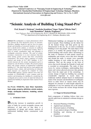
BADGERINDUSTRIESSEISMIC HARDWAREwww.NUSIG.comSales@NUSIG.com2019 Edition BADGER INDUSTRIES [2] FM Global 1950-10 & 1950-13Brace Angle From VerticalDetail (SHVT-SPCA) Anvil[1] ANVILFig. 212Fig. 212FPSize & ClampPart Number[1] BADGER[3] [4] Steel Schedule(7 thru 80) PipeINDUSTRIESAnd RMC ConduitSeismic HardwareNominal SizePart Number0º Vert. 30º to 44º 45º to 60º 61º to 75º90ºMaximumFpv (LRFD)MaximumFp (LRFD)MaximumFp (LRFD)MaximumFp (LRFD)MaximumFp (LRFD)801 lbs.925 lbs.1" Fig. 212SBEMT1 in.925 lbs.462 lbs.653 lbs.1-1/4" Fig. 212SBEMT1-1/4 in.1,155 lbs.577 lbs.816 lbs.1,000 lbs. 1,155 lbs.1-1/2" Fig. 212SBEMT1-1/2 in.1,215 lbs.607 lbs.859 lbs.1,052 lbs. 1,215 lbs.2" Fig. 212SBEMT2 in.1,945 lbs.972 lbs.2-1/2" Fig. 212SBEMT2-1/2 in.4,405 lbs. 2,202 lbs. 3,114 lbs. 3,814 lbs. 4,405 lbs.3" Fig. 212SBEMT3 in.4,405 lbs. 2,202 lbs. 3,114 lbs. 3,814 lbs. 4,405 lbs.3-1/2" Fig. 212SBEMT3-1/2 in.3,635 lbs. 1,817 lbs. 2,569 lbs. 3,147 lbs. 3,635 lbs.4" Fig. 212SBEMT4 in.4,405 lbs. 2,202 lbs. 3,114 lbs. 3,814 lbs. 4,405 lbs.5" Fig. 212FPSBEMT5 in.4,405 lbs. 2,202 lbs. 3,114 lbs. 3,814 lbs. 4,405 lbs.6" Fig. 212FPSBEMT6 in.4,405 lbs. 2,202 lbs. 3,114 lbs. 3,814 lbs. 4,405 lbs.8" Fig. 212FPSBEMT8 in.4,720 lbs. 2,360 lbs. 3,337 lbs. 4,087 lbs. 4,720 lbs.10" Fig. 212FPSBEMT10 in.4,630 lbs. 2,315 lbs. 3,273 lbs. 4,009 lbs. 4,630 lbs.12" Fig. 212FPSBEMT12 in.2,930 lbs. 1,465 lbs. 2,071 lbs. 2,537 lbs. 2,930 lbs.1,375 lbs. 1,684 lbs. 1,945 lbs.[1] No Substitution[2] Per FM, (ASD) (LRFD / 1.5).[3] (1" thru 6") Schedule 7 (Or Thicker Wall) Pipe Conforming To ASTM A-53 Grade A, Or B With A Minimum (30,000 psi) YieldStrength Or Equivalent.(8" thru 12") Schedule 10 (Or Thicker Wall) Pipe Conforming To ASTM A-53 Grade A, Or B With A Minimum (30,000 psi) YieldStrength Or Equivalent.[4] (1" thru 6") RIGID Conduit Conforming To UL-6 Or ANSI C-80.3 With A Minimum (30,000 psi) Yield Strength Or Equivalent.VerticalFpvPer ChartVertical[1] BADGERINDUSTRIES(SBEMT)BraceAnglePer ChartFOR BRACING OFSTEEL PIPING ANDRMC CONDUIT:ANVIL Fig. 212 And FIG. 212FP Assembly:Anvil International LLC referred to as ANVILHorizontalFpPer ChartFor Sizes (1" thru 2"):Nut 11.) Tighten Hex Nut 1, Until Clamp Ears Contact Badger SBEMT.2.) Tighten Hex Nut 2, Until Clamp Ears Contact Each Other.For Sizes (2-1/2" thru 12"):Nut 2[1] ANVIL Fig. 212Or ANVIL Fig. 212FPPer Chart1.) Tighten Hex Nut 1 And Hex Nut 2 Until Clamp Ears AreEqually Spaced (Visually).2.) Tighten (Alternately) Hex Nuts 1 And 2 An Additional (2)Turns. Alternate Tightening Hex Nut 1 and Hex Nut 2, Every(1) Turn. BADGER INDUSTRIES SHVT-SPCASingle Hanger Vertical & Transverse - Design Demand Capacity Limits(Elev. View) - (Not To Scale) - (Read General Notes Prior To Use)
BADGERINDUSTRIESSEISMIC HARDWAREwww.NUSIG.comSales@NUSIG.com2019 Edition BADGER INDUSTRIES [2] FM Global 1950-10 & 1950-13Brace Angle From VerticalDetail (SHVT-CIPA) Anvil[1] ANVILFig. 212Fig. 212FPSize & ClampPart Number[1] BADGERINDUSTRIESSeismic HardwarePart Number[7] No HubCast-Iron PipeNominal Size1-1/2" Fig. 212SBEMT1-1/2 in.2,210 lbs. 1,105 lbs. 1,562 lbs. 1,913 lbs. 2,210 lbs.2" Fig. 212SBEMT2 in.3,490 lbs. 1,745 lbs. 2,467 lbs. 3,022 lbs. 3,490 lbs.3" Fig. 212SBEMT3 in.3,020 lbs. 1,510 lbs. 2,135 lbs. 2,615 lbs. 3,020 lbs.4" Fig. 212SBEMT4 in.3,790 lbs. 1,895 lbs. 2,679 lbs. 3,282 lbs. 3,790 lbs.5" Fig. 212FPSBEMT5 in.3,870 lbs. 1,935 lbs. 2,736 lbs. 3,351 lbs. 3,870 lbs.6" Fig. 212FPSBEMT6 in.3,480 lbs. 1,740 lbs. 2,460 lbs. 3,013 lbs. 3,480 lbs.8" Fig. 212FPSBEMT8 in.2,615 lbs. 1,307 lbs. 1,848 lbs. 2,264 lbs. 2,615 lbs.10" Fig. 212FPSBEMT10 in.2,695 lbs. 1,347 lbs. 1,905 lbs. 2,333 lbs. 2,695 lbs.12" Fig. 212FPSBEMT12 in.2,105 lbs. 1,052 lbs. 1,488 lbs. 1,822 lbs. 2,105 lbs.0º Vert. 30º to 44º 45º to 60º 61º to 75ºMaximumFpv (LRFD)MaximumFp (LRFD)MaximumFp (LRFD)MaximumFp (LRFD)90ºMaximumFp (LRFD)[1] No Substitution[2] Per FM, (ASD) (LRFD / 1.5).[7] No Hub Cast-Iron Piping Conforming To ASTM A888 / CISPI 301 Standards With A Minimum (21,000 psi) Tensile Strength.VerticalFpvPer ChartVertical[1] BADGERINDUSTRIES(SBEMT)FOR BRACING OFCAST-IRON PIPING:ANVIL Fig. 212 And FIG. 212FP Assembly:BraceAnglePer ChartAnvil International LLC referred to as ANVILFor Sizes (1-1/2" and 2"):1.) Tighten Hex Nut 1, Until Clamp Ears C
the design and/or assembly of seismic vertical hangers and/or seismic transverse or longitudinal bracing, unless such components have been seismically tested and/or engineered by others for such seismic assembly conditions. Installer shall clean seismic h