Transcription
SEISMIC DESIGN OFREINFORCED CONCRETE STRUCTURESInstructional Material Complementing FEMA 451, Design ExamplesDesign for Concrete Structures 11 - 1Topic 11 is the seismic design of reinforced concrete structures, primarily buildings.During this lesson you will learn the basics of seismic design of reinforced concretebuildings. Buildings designed using these principles will fare better in a seismicevent than the building shown in this slide.Note that some of the examples in this topic draw heavily on the examples in theFEMA 451, NEHRP Recommended Provisions: Design Examples. Please seeChapter 6 of that CD for additional details regarding these examples.FEMA 451B Topic 11 NotesReinforced Concrete Structures 11 - 1
NEHRP Recommended ProvisionsConcrete Design Requirements Context in the NEHRP Recommended ProvisionsConcrete behaviorReference standardsRequirements by Seismic Design CategoryMoment resisting framesShear wallsOther topicsSummaryInstructional Material Complementing FEMA 451, Design ExamplesDesign for Concrete Structures 11 - 2This slide presents the outline of this presentationFEMA 451B Topic 11 NotesReinforced Concrete Structures 11 - 2
Context in NEHRP RecommendedProvisionsDesign basis: Strength limit stateUsing NEHRP Recommended Provisions:Structural design criteria:Chap. 4Structural analysis procedures:Chap. 5Components and attachments:Chap. 6Design of concrete structures:Chap. 9andACI 318Instructional Material Complementing FEMA 451, Design ExamplesDesign for Concrete Structures 11 - 3The 2003 NEHRP Recommended Provisions (FEMA 450) uses strength limit statefor design of concrete (and all other materials). Since ACI 318 provides ultimatestrength procedures, the Provisions design will be very familiar to most engineers.Required strength (demand) is determined from Provisions Chapters 4 and 5 andprovided strength (capacity) is calculated using Chapter 9. The chapters ofProvisions that affect concrete design are as follows: Chapter 4 for loadcombinations and R and Cd factors, Chapter 5 for seismic load determination anddistribution, Chapter 6 for specific component and attachment requirements, andChapter 9 for the design of concrete elements and connections. Chapter 9 alsoprovides detailing provisions that are used to ensure stable inelastic behavior.FEMA 451B Topic 11 NotesReinforced Concrete Structures 11 - 3
Seismic-Force-Resisting SystemsReinforced ConcreteUnbraced frames (withrigid “moment resisting” joints):Three typesOrdinaryIntermediateSpecialR/C shear walls:OrdinarySpecialPrecast shear walls:SpecialIntermediateOrdinaryInstructional Material Complementing FEMA 451, Design ExamplesDesign for Concrete Structures 11 - 4Two possible seismic resisting systems using reinforced concrete are momentframes and shear walls. Provisions Chapter 4 presents design coefficients andsystem limitations for various Seismic Design Categories. Precast walls can beused, however they will not be addressed in detail in this lecture. To understandsome of the detailing requirements and how they relate to the ductility of thesestructural systems, we will first review basic reinforced concrete behavior.FEMA 451B Topic 11 NotesReinforced Concrete Structures 11 - 4
NEHRP Recommended ProvisionsConcrete Design Context in the Provisions Concrete behaviorInstructional Material Complementing FEMA 451, Design ExamplesDesign for Concrete Structures 11 - 5This section will discuss mechanical properties of reinforcing steel and concrete andhow the two materials work together in reinforced concrete members.FEMA 451B Topic 11 NotesReinforced Concrete Structures 11 - 5
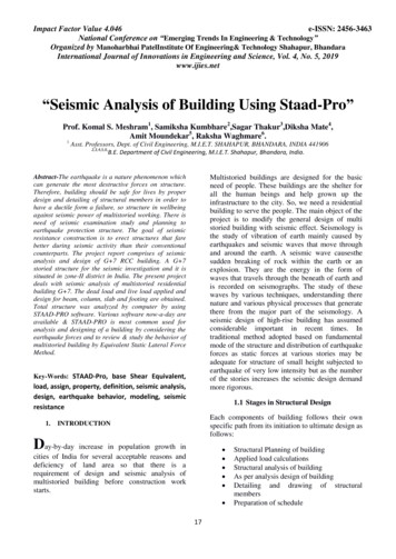
Unconfined Concrete Stress-Strain Behavior200004500 psi8800 psi13,500 psi17,500 psi1800016000Stress, 30.004Strain, in./in.Instructional Material Complementing FEMA 451, Design ExamplesDesign for Concrete Structures 11 - 6This slide presents stress-strain diagrams for unreinforced, unconfined concrete incompression. Behavior is relatively linear up to about one-half of the maximumcompressive stress. Concrete exhibits no precise yield point. Strain at maximumstrength is close to 0.002 regardless of maximum stress. Lower strength concretecan have strains at crushing that exceed 0.004, however a typical design value is0.003 at crushing. Stronger concretes are more brittle.FEMA 451B Topic 11 NotesReinforced Concrete Structures 11 - 6
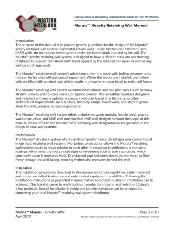
Idealized Stress-Strain Behaviorof Unconfined Concrete6000Stress, psi50004000 2ε ε 2 fc f c c ε o ε o 2f 'εo cEt3000'c20001000Et 1.8 x10⁶ 460fc' , psi000.0005 0.001 0.0015 0.002 0.0025 0.003 0.0035 0.004StrainInstructional Material Complementing FEMA 451, Design ExamplesDesign for Concrete Structures 11 - 7This slide shows one commonly used, relatively simple, idealized model of thestress-strain behavior of unconfined concrete (Hognestad). This type ofmathematical model can be used in a strain compatibility approach to predictbehavior of reinforced concrete members.FEMA 451B Topic 11 NotesReinforced Concrete Structures 11 - 7
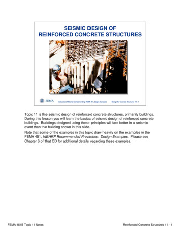
Confinement by Spirals or HoopsAspfyhAspdsfyhAspConfinementfrom spiral orcircular hoopForces actingon 1/2 spiral orcircular hoopInstructional Material Complementing FEMA 451, Design ExamplesConfinementfrom squarehoopDesign for Concrete Structures 11 - 8Confining reinforcing can improve concrete behavior in two ways. First it canenhance strength by restraining lateral strains. Second it can increase the usableconcrete compressive strain well beyond the typical value of 0.003.This slide shows confinement in practical structural sections. Confinement istypically provided by spirals, circular hoops, or square hoops. The hatched areas inthe figures may spall. Confining steel is in tension (hoop stress effect) because,due to Poisson’s effect, as the concrete is compressed in one direction, it expandsin the orthogonal directions. This is shown in the center illustration. Note thathoops are not as efficient as spirals in confining concrete because the sides of thehoop can flex outward as the confined concrete expands outward.FEMA 451B Topic 11 NotesReinforced Concrete Structures 11 - 8
ConfinementRectangular hoopswith cross tiesConfinement bytransverse barsInstructional Material Complementing FEMA 451, Design ExamplesConfinement bylongitudinal barsDesign for Concrete Structures 11 - 9This slide shows confinement for a square column, which can be provided bytransverse and longitudinal bars. The hatched areas may spall.FEMA 451B Topic 11 NotesReinforced Concrete Structures 11 - 9
Opened 90 hook on hoopsInstructional Material Complementing FEMA 451, Design ExamplesDesign for Concrete Structures 11 - 10This slide shows 90 degree hooks on square hoops which have opened. As statedearlier, the confining steel is in tension. After spalling, the hooks can open up. Thesolution is to use 135 degree hooks. The arrow points to an open hook.FEMA 451B Topic 11 NotesReinforced Concrete Structures 11 - 10
Confined Concrete Stress-Strain Behaviorno confinement4.75 in.Pitch of3.5 in.¼ in. dia.2.375 in.spiral1.75 in.80007000Stress, psi6000500040003000Tests of6 in. x 12 in.cylinders20001000000.010.020.030.04Average strain on 7.9 in. gauge lengthInstructional Material Complementing FEMA 451, Design ExamplesDesign for Concrete Structures 11 - 11This slide shows the benefits of confinement on concrete behavior. Presented arestress-strain diagrams for confined concrete in compression. The specimens were6 in. by 12 in. cylinders. Confinement was provided by spiral reinforcement.Reducing spiral pitch (or hoop spacing) increases maximum concrete stress andstrain capacity (ductility).FEMA 451B Topic 11 NotesReinforced Concrete Structures 11 - 11
Idealized Stress-Strain Behavior ofConfined ConcreteKent and Park ModelNo Hoops4 in.6 in.9 in.12 in.45004000Stress, psi350030002500200015001000500000.004Confined Area 12” x 16”0.0080.0120.016Strain, in./in.Instructional Material Complementing FEMA 451, Design ExamplesDesign for Concrete Structures 11 - 12This slide shows the idealized stress-strain behavior of confined concrete proposedby Kent and Park. Note that the model reflects the additional strain, but not theadditional strength, provided by the confinement. Another model that reflects bothstrength and strain gain is Scott, Park, and Priestley. This type of model can beused with the strain compatability method to predict the behavior of confinedreinforced concrete.FEMA 451B Topic 11 NotesReinforced Concrete Structures 11 - 12
Reinforcing Steel Stress-Strain Behavior100Grade 75Stress, ksi80Grade 60rupture 10-12%60Grade 4040strain hardening 1-3%rupture 18-20%E 29,000 structional Material Complementing FEMA 451, Design ExamplesDesign for Concrete Structures 11 - 13This slide shows typical stress-strain behavior of common grades of reinforcingsteel. The most commonly used is Grade 60 which shows a distinct yield plateauand strain hardening at between 0.5% and 1% elongation. For common analysis ofreinforced concrete behavior, strain hardening is ignored. For seismic design, it isimportant that the actual yield strain of the steel is not significantly higher than thevalue used in design.FEMA 451B Topic 11 NotesReinforced Concrete Structures 11 - 13
Reinforced Concrete cked-elasticuncrackedMid-Point Displacement, ΔInstructional Material Complementing FEMA 451, Design ExamplesDesign for Concrete Structures 11 - 14This slide shows stages of behavior of a reinforced concrete beam. At low loadsthe section is uncracked and an analysis using uncracked-transformed sectionproperties can be used to predict behavior. After the concrete cracks, the concreteon the tension side of the beam is neglected, and a cracked-transformed sectionanalysis can be used to predict behavior. However, this method is only valid aslong as both the steel and the concrete stress-strain behaviors are linear. Concretecan be assumed to have a linear stress-strain behavior up to approximately 50% ofmaximum concrete stress (f’c).After the concrete stress exceeds about 50%f’c, a strain compatibility approach canbe used, using a realistic concrete stress-strain model such as the Hognestadmodel presented in Slide 7. After the steel yields, there is typically an extendedplateau in which the displacement increases significantly with very little increase inapplied load. A commonly used indicator of member ductility is the ratio of thedisplacement at ultimate to the displacement at first yield. This is known at thedisplacement ductility, and for seismic design in particular, bigger is better.FEMA 451B Topic 11 NotesReinforced Concrete Structures 11 - 14
Behavior Up to First Yield of SteelbεcfccφdAsεsStrainInstructional Material Complementing FEMA 451, Design ExamplesεsEs fyStressDesign for Concrete Structures 11 - 15To characterize section behavior, moment-curvature (M-φ) diagrams are oftenemployed. This slide shows the type of strain compatibility approach that would beused to locate points on the curve up until first yield of the steel. To locate a point,first a concrete strain is selected. Then an iterative method is used in which thedepth to the neutral axis is assumed and modified until internal equilibrium isachieved. The tension force is equal to the strain (based on the strain diagram withthe selected concrete strain and neutral axis depth) times the area and the modulusof elasticity of the steel. The compression force is determined by integrating underthe stress-position curve from the neutral axis to the extreme compression fiber,and multiplying by the width of the beam. The value of “c” is adjusted until C T.Then the curvature is calculated as the concrete strain divided by the neutral axisdepth, and the moment is the force (T or C) times the distance between the forces.This can be repeated for several selected concrete strains to determine points onthe M-φ diagram.FEMA 451B Topic 11 NotesReinforced Concrete Structures 11 - 15
Behavior at Concrete Crushingbε c,maxf'ccCφdAsεs εyStrainjdAsfyfyStressForcesMn AsfyjdInstructional Material Complementing FEMA 451, Design ExamplesDesign for Concrete Structures 11 - 16After yield but before the onset of strain hardening, the same method as presentedon the previous slide can be used; however, the force in the steel will be Asfy. Thismethod can be used for points up to the concrete crushing strain of 0.003. TheWhitney stress block method is a good method to calculate the final point on themoment curvature diagram, but cannot be used for other points. Typically strainhardening is not considered in design.FEMA 451B Topic 11 NotesReinforced Concrete Structures 11 - 16
Typical Moment Curvature Diagram700w/ strain hardeningM, in-kip600f’c 4 ksi500fy 60 ksiw/o strain hardeningb 8 in400d 10 in300ρ 0.012520010000100200φx10-5300in-1Instructional Material Complementing FEMA 451, Design ExamplesDesign for Concrete Structures 11 - 17This slide shows moment-curvature diagrams for a rectangular section in flexure.Strain hardening in the tension steel increases the final strength. A concrete strainof 0.003 corresponds to maximum strength.FEMA 451B Topic 11 NotesReinforced Concrete Structures 11 - 17
Influence of Reinforcement Ratio5000f’c 4 ksiM, in-kip4000fy 60 ksib 10 in3000d 18 in2000ρ 2.5%ρ 1.5%ρ 0.5%100000100200300400φ x 10-5 in-1Instructional Material Complementing FEMA 451, Design ExamplesDesign for Concrete Structures 11 - 18This slide shows moment-curvature diagrams for various amounts of tensionreinforcement. As the steel percentage increases, the moment capacity alsoincreases, but the curvature at ultimate moment capacity is decreased (lessductility). Ductile behavior is very desirable in seismic force resisting systems. Acommon measure of ductility is the ratio of curvature at first yield to curvature atultimate. This is known as curvature ductility.FEMA 451B Topic 11 NotesReinforced Concrete Structures 11 - 18
Influence of Compression Reinforcement160012003Beam12314564 725800Mlb / 24φInstructional Material Complementing FEMA 451, Design ExamplesDesign for Concrete Structures 11 - 19This slide shows moment-curvature diagrams for various amounts of tension andcompression reinforcement. An increase in the compression reinforcement ratioonly slightly increases moment capacity but significantly increases curvature atultimate moment capacity (more ductility). This is because when the tension forcedoes not change (ρ is constant) and neither does the compression force. Withlarger amounts of compression reinforcement the steel carries more of thecompression, so the concrete carries less. This means the depth to the neutral axisis more shallow, so the curvature at ultimate (0.003/c) is larger. However, since Cand T do not change and there is only a slight increase in the moment arm, themoment capacity only increases slightly. (Note: Curve 7 stops at about 0.025; Curve6 continues off the graph.)FEMA 451B Topic 11 NotesReinforced Concrete Structures 11 - 19
Moment-Curvaturewith Confined Concreteε c,maxf'ccφAsεs εyStrainInstructional Material Complementing FEMA 451, Design ExamplesfyStressDesign for Concrete Structures 11 - 20The presence of confining reinforcement can significantly increase the maximumachievable curvature. After the strain on the compression face exceeds 0.003, thecover over the confining steel will spall, however the concrete within the core willremain intact. A model such as the Kent and Park model presented earlier can beused with the strain compatibility method to calculate moments and correspondingcurvatures.FEMA 451B Topic 11 NotesReinforced Concrete Structures 11 - 20
Moment-Curvature with ConfinedConcrete35000Moment, in-k3000025000Beam - 24 in. x 36 in.Tension Steel - 12 ea. #10Compression Steel - 5 ea. #8Confining Steel - #4 hoops at 4 in. c-c2000015000100005000without confiningwith confining00500100015002000curvature, microstrain/in.Instructional Material Complementing FEMA 451, Design ExamplesDesign for Concrete Structures 11 - 21This slide presents the results of the analysis of a beam, whose dimensions andreinforcing details are given on the slide. As you can see, the addition of theconfining reinforcing increases the usable curvature from just under 500 microstrainper inch to just over 1600. The Scott, Park, and Preistley model was used to modelthe behavior of the confined concrete. This model accounts for the increase inconcrete compressive strength. In addition the compression steel was able to yield,and strain hardening was considered in the tension steel. These three factorscombined to result in an increase in moment capacity from the confining steel, eventhough the cover concrete was lost.FEMA 451B Topic 11 NotesReinforced Concrete Structures 11 - 21
Plastic HinginglidealizedφMlpMuφu φyφuInstructional Material Complementing FEMA 451, Design ExamplesactualplasticrotationDesign for Concrete Structures 11 - 22This slide shows how spreading plasticity can significantly increase plastic rotationand displacements. The curvature diagram shows a region of very high curvatures(beyond the yield curvature, φy) at maximum moment and elastic response in otherregions. The region of curvatures past yield curvature is known as the plastic hingeregion. The irregular curvature on the “actual” curve is due to cracking.The plastic rotation and the tip displacement can be calculated from the “actual”curvature diagram, or from the idealized curvature diagram. The idealized diagramis based on a bi-linear approximation of the moment-curvature diagram and anassumed length of the plastic hinge, lp.FEMA 451B Topic 11 NotesReinforced Concrete Structures 11 - 22
Strategies to Improve Ductility Use low flexural reinforcement ratio Add compression reinforcement Add confining reinforcementInstructional Material Complementing FEMA 451, Design ExamplesDesign for Concrete Structures 11 - 23This discussion presented three strategies for improving ductility. These arepresented in this slide.FEMA 451B Topic 11 NotesReinforced Concrete Structures 11 - 23
Other Functions of Confining Steel Acts as shear reinforcement Prevents buckling of longitudinal reinforcementPrevents bond splitting failuresInstructional Material Complementing FEMA 451, Design ExamplesDesign for Concrete Structures 11 - 24Confining reinforcing also has other useful functions that are presented in this slide.FEMA 451B Topic 11 NotesReinforced Concrete Structures 11 - 24
Structural BehaviorFramesStory MechanismSway MechanismInstructional Material Complementing FEMA 451, Design ExamplesDesign for Concrete Structures 11 - 25With an understanding of reinforced concrete member behavior, reinforced concretesystems can be designed to ensure acceptable behavior in a seismic event. We willnow discuss desirable system behaviors.The goal in design of structural frames is to size and reinforce members such thatwhen subjected to large lateral displacements the hinges form in the beamsadjacent to the columns, but the columns remain relatively undamaged. This isknown as the “strong column-weak beam” approach that is illustrated in the rightframe in this slide. A “weak column-strong beam” design can result in theundesirable story mechanism, also known as a soft story, that is shown in the leftillustration.FEMA 451B Topic 11 NotesReinforced Concrete Structures 11 - 25
Story MechanismInstructional Material Complementing FEMA 451, Design ExamplesDesign for Concrete Structures 11 - 26This slide illustrates a story mechanism.FEMA 451B Topic 11 NotesReinforced Concrete Structures 11 - 26
Structural Behavior - onSliding onflexural cracksInstructional Material Complementing FEMA 451, Design ExamplesSliding onconstructionjointDesign for Concrete Structures 11 - 27This figure shows types of failures in shear walls. The left figure shows a flexuralfailure with a plastic hinge zone at the base of the wall. The second figure showsthat severe cracking necessitates that web reinforcement carries the horizontalshear force. The last two figures show types of sliding failures: sliding along fulldepth flexural cracks or along construction joints. The most desirable is the flexuralfailure with other modes precluded. With proper detailing, the wall can exhibit goodstrength and ductility without excessive drift or collapse.FEMA 451B Topic 11 NotesReinforced Concrete Structures 11 - 27
Structural nal Material Complementing FEMA 451, Design ExamplesDesign for Concrete Structures 11 - 28This slide shows how both horizontal and vertical reinforcement provide shearresistance for low-rise shear walls.FEMA 451B Topic 11 NotesReinforced Concrete Structures 11 - 28
Structural BehaviorColumnsUltimateyield100014 in square4-#11 barsf' c 4 ksif y 45 ksiAxial load, P, kip8006001.75”bending axis40020000400800120016000.002Moment, M, in-kipInstructional Material Complementing FEMA 451, Design Examples0.0010Curvature, φ, rad/inDesign for Concrete Structures 11 - 29In strong column-weak beam design, undesirable failures in the columns must beprecluded through proper design and detailing. This slide presents the P-M curveon the left and the P-curvature curve on the right. Note that the presence of largeaxial loads reduces the curvature at ultimate. Axial loads above the balanced pointreduce ductility of beam-columns since the reinforcing steel on the tension side ofthe column never yields. Confinement reinforcement improves axial ductility, butthis plot shows curvature ductility, which is more important in frames. The strongcolumn-weak beam design approach ensures that failure will initiate in ductilebeams rather than in brittle columns.FEMA 451B Topic 11 NotesReinforced Concrete Structures 11 - 29
Influence of Hoops on Axial StrengthGross columnArea A gBefore spallingP Agf’cConfined concreteArea A coreAfter spallingP Acore(f’c 4 flat)After spalling Before spallingInstructional Material Complementing FEMA 451, Design ExamplesDesign for Concrete Structures 11 - 30The strength of an unconfined concrete column is the gross area times theunconfined compressive strength. After the concrete outside the spiral, hoops orties has spalled, the strength of the column is the core area times the enhancedcompressive strength. Work done in the 1920s by Richart et al. indicated thatconfined concrete strength is roughly the unconfined strength plus 4 times theconfining pressure, flat. The goal in designing the hoops is to ensure that thestrength after cover spalling is not less than the strength before spalling.FEMA 451B Topic 11 NotesReinforced Concrete Structures 11 - 30
Column withInadequate TiesInstructional Material Complementing FEMA 451, Design ExamplesDesign for Concrete Structures 11 - 31This photo shows a column with inadequate ties which provided almost noconfinement. Olive View Hospita after the 1971 San Fernando earthquake.FEMA 451B Topic 11 NotesReinforced Concrete Structures 11 - 31
Well Confined ColumnInstructional Material Complementing FEMA 451, Design ExamplesDesign for Concrete Structures 11 - 32This slide shows a column with an adequate amount of spiral confinement. Afterthe cover spalled, the well confined core remains intact and able to carry axialloads. Olive View Hospital after the 1971 San Fernando earthquake.FEMA 451B Topic 11 NotesReinforced Concrete Structures 11 - 32
Hysteretic Behavior of Well ConfinedColumnM 1.0Mu0.54-4-0.5Drift, %-1.0Instructional Material Complementing FEMA 451, Design ExamplesDesign for Concrete Structures 11 - 33This type of hysteresis loop shows good performance of a column with generousconfinement reinforcement. The preferred type of hysteresis loop shows only smalldegradation of moment strength with increased imposed drift. Also the loopsremain “fat” which indicates good energy dissipation.FEMA 451B Topic 11 NotesReinforced Concrete Structures 11 - 33
ΔStructural BehaviorColumnsM1M1VVLVM2V M1 M2 2Mu LLM2PRangeof PMoInstructional Material Complementing FEMA 451, Design ExamplesMuMDesign for Concrete Structures 11 - 34To ensure strong column-weak beam behavior, shear failures of columns must alsobe precluded. However, shear in a concrete column can be critical. Shear ismaximum in a column when the moments at each end are at ultimate. The momentcapacity of a column depends on the magnitude of the axial load. To avoid shearfailures, the design should focus on the axial load that produces the largest momentcapacity. The P-M interaction diagram shows this range of axial loads for anexample column.FEMA 451B Topic 11 NotesReinforced Concrete Structures 11 - 34
Column Shear FailureInstructional Material Complementing FEMA 451, Design ExamplesDesign for Concrete Structures 11 - 35This photo shows a shear failure of a bridge pier after the 1971 San Fernandoearthquake.FEMA 451B Topic 11 NotesReinforced Concrete Structures 11 - 35
Structural BehaviorJointsVfchftTCcCsMax. shear forceVj T- VInstructional Material Complementing FEMA 451, Design ExamplesDesign for Concrete Structures 11 - 36Another location in frames where premature failures must be precluded is the beamcolumn joints. This slide shows joint actions. The left figure shows forces(stresses) imposed on a typical exterior joint, and the right shows cracks. Uponreversal of direction, perpendicular cracks form. The anchorage of thereinforcement can be compromised. The important aspects of joint design areensuring proper bar development and precluding shear failures in the joint. Thiscan be accomplished through proper detailing of hoop reinforcement and bar hooks.FEMA 451B Topic 11 NotesReinforced Concrete Structures 11 - 36
Hysteretic Behavior of Joint with HoopsMMu1.00.55 6Drift, %-1-0.5Instructional Material Complementing FEMA 451, Design ExamplesDesign for Concrete Structures 11 - 37This slide shows a typical hysteresis loop for a joint with hoops. The joint showsgood performance under repeated reversed loads.FEMA 451B Topic 11 NotesReinforced Concrete Structures 11 - 37
Hysteretic Behavior of Joint with No HoopsMMu1.00.55 6Drift, %-1-0.5Instructional Material Complementing FEMA 451, Design ExamplesDesign for Concrete Structures 11 - 38This slide shows a typical hysteresis loop of a joint without confining hoops. Notethe rapid deterioration of the joint.FEMA 451B Topic 11 NotesReinforced Concrete Structures 11 - 38
Joint Failure – No Shear ReinforcingInstructional Material Complementing FEMA 451, Design ExamplesDesign for Concrete Structures 11 - 39This photo is of a joint failure in shear (1971 San Fernando earthquake). Note thatthere is NO shear reinforcement in the joint and the joint is too small. The joint canno longer transmit moments.FEMA 451B Topic 11 NotesReinforced Concrete Structures 11 - 39
Anchorage Failure inColumn/Footing JointInstructional Material Complementing FEMA 451, Design ExamplesDesign for Concrete Structures 11 - 40Another type of failure which must be prevented in order to ensure ductile framebehavior is the failure of the joint between the column and the footing. This slideshows an anchorage failure of a bridge column (1971 San Fernando earthquake).FEMA 451B Topic 11 NotesReinforced Concrete Structures 11 - 40
Summary of Concrete Behavior Compressive Ductility– Strong in compression but brittle– Confinement improves ductility by Maintaining concrete core integrity Preventing longitudinal bar buckling Flexural Ductility– Longitudinal steel provides monotonic ductility at lowreinforcement ratios– Transverse steel needed to maintain ductility throughreverse cycles and at very high strains (hingedevelopment)Instructional Material Complementing FEMA 451, Design ExamplesDesign for Concrete Structures 11 - 41We will now review reinforced concrete behavior.Concrete is strong in compression but brittle. Confinement improves compressiveductility by limiting transverse expansion in the concrete. As the transverse steelties take the strain in tension, the concrete core maintains its integrity. Closelyspacing the ties will limit longitudinal bar buckling and thus contribute to improvedcompressive ductility. Longitudinal steel provides flexural ductility at lowreinforcement ratios for a single overload. Transverse steel is needed to maintainintegrity of the concrete core (which carries compression and shear), and preventlongitudinal bar buckling after the cover has spalled and crossing cracks form. Arelative balance of tension and compression steel aids flexural ductility. Theamount of longitudinal tension steel must be limited to insure a tension-type failuremode.FEMA 451B Topic 11 NotesReinforced Concrete Structures 11 - 41
Summary of Concrete Behavior Damping– Well cracked: moderately high damping– Uncracked (e.g. prestressed): low damping Potential Problems– Shear failures are brittle and abrupt and must beavoided– Degrading strength/stiffness with repeat cycles Limit degradation through adequate hingedevelopmentInstructional Material Complementing FEMA 451, Design ExamplesDesign for Concrete Structures 11 - 42The level of damping in concrete structures depends on the amount of cracking. Itis important to avoid potential problems in concrete structures: shear failures inconcrete are brittle and abrupt and must be avoided; repeated loadings degradestrength and stiffness as concrete cracks and steel yields. Degradation can belimited by assuring adequate hinge development.FEMA 451B Topic 11 NotesReinforced Concrete Structures 11 - 42
NEHRP Recommended ProvisionsConcrete Design Context in the Provisions Concrete behavior Re
Topic 11 is the seismic design of reinforced concrete structures, primarily buildings. During this lesson you will learn the basics of seismic design of reinforced concrete buildings. Buildings desi