Transcription
Seismic DesignManualVolume ICode Application Examples
CopyrightCopyright 1999 Structural Engineers Association of California. All rights reserved.This publication or any part thereof must not be reproduced in any form without thewritten permission of the Structural Engineers Association of California.PublisheStructural Engineers Association of California (SEAOC)555 University Avenue, Suite 126Sacramento, California 95825-6510Telephone: (916) 427-3647; Fax: (916) 568-0677E-mail: seaoc@aol.com; Web address: www.seaint.orgThe Structural Engineers Association of California (SEAOC) is a professionalassociation of four regional member organizations (Central California, NorthernCalifornia, San Diego, and Southern California). SEAOC represents the structuralengineering community in California. This document is published in keeping withSEAOC’s stated mission: “to advance the structural engineering profession; toprovide the public with structures of dependable performance through the applicationof state-of-the-art structural engineering principles; to assist the public in obtainingprofessional structural engineering services; to promote natural hazard mitigation; toprovide continuing education and encourage research; to provide structural engineerswith the most current information and tools to improve their practice; and to maintainthe honor and dignity of the profession.”EditorGail Hynes Shea, Albany, California, shea@slip.netDisclaimePractice documents produced by the Structural Engineers Association of California(SEAOC) and/or its member organizations are published as part of our association’seducational program. While the information presented in this document is believed tobe correct, neither SEAOC nor its member organizations, committees, writers,editors, or individuals who have contributed to this publication make any warranty,expressed or implied, or assume any legal liability or responsibility for the use,application of, and/or reference to opinions, findings, conclusions, orrecommendations included in this publication. The material presented in thispublication should not be used for any specific application without competentexamination and verification of its accuracy, suitability, and applicability by qualifiedprofessionals. Users of information from this publication assume all liability arisingfrom such use.
Table of Contents Preface. . vAcknowledgments. .viIntroduction . . 1Notation. . 3Example 1Earthquake Load Combinations:Strength Design . §1612.2. 7Example 2Combinations of Loads . §1612.3. 12Example 3Seismic Zone 4 Near-Source Factor . §1629.4.2. 17Introduction to Vertical Irregularities . §1629.5.3. 20Example 4Vertical Irregularity Type 1 . §1629.5.3. 21Example 5Vertical Irregularity Type 2 . §1629.5.3. 24Example 6Vertical Irregularity Type 3 . §1629.5.3. 26Example 7Vertical Irregularity Type 4 . §1629.5.3. 28Example 8Vertical Irregularity Type 5 . §1629.5.3. 30Example 9Vertical Irregularity Type 5 . §1629.5.3. 32Introduction to Plan Irregularities . §1629.5.3. 36Example 10 Plan Irregularity Type 1 . §1629.5.3. 37Example 11 Plan Irregularity Type 2 . §1629.5.3. 41Example 12 Plan Irregularity Type 3 . §1629.5.3. 43Example 13 Plan Irregularity Type 4 . §1629.5.3. 45Example 14 Plan Irregularity Type 5 . §1629.5.3. 46Example 15 Reliability/Redundancy Factor ρ . §1630.1.1. 47Example 16 Reliability/Redundancy Factor Applications. §1630.1.1. 52Example 17 P Effects. §1630.1.3. 56Example 18 Design Base Shear . §1630.2.1. 59Example 19 Structure Period Using Method A. §1630.2.2. 61Example 20 Simplified Design Base Shear. §1630.2.3. 65Example 21 Combination of Structural Systems: Vertical. §1630.4.2. 68Example 22 Combination of Structural Systems:Along Different Axes. §1630.4.3. 71Example 23 Combination of Structural Systems:Along the Same Axis . §1630.4.4. 73Example 24 Vertical Distribution of Force . §1630.5. 74Example 25 Horizontal Distribution of Shear. §1630.6. 76Example 26 Horizontal Torsional Moments . §1630.7. 81SEAOC Seismic Design Manual
Table of ContentsTable of Contents (continued)Example 27Example 28Example 29Example 30Example 31Example 32Example 33Example 34Example 35Example 36Example 37Example 38Example 39Example 40Example 41Example 42Example 43Example 44Example 45Example 46Example 47Example 48Example 49Example 50Example 51Example 52Example 53Example 54Example 55 Elements Supporting Discontinuous Systems. §1630.8.2.85Elements Supporting Discontinuous Systems. §1630.8.2.88At Foundation. §1630.8.3.90Drift . §1630.9.96Story Drift Limitations . §1630.10.98Vertical Component . §1630.11.100Design Response Spectrum . §1631.2.101Dual Systems. §1631.5.7.104Lateral Forces for One-Story Wall Panels. §1632.2.107Lateral Forces for Two-Story Wall Panel . §1632.2.111Rigid Equipment. §1632.2.116Flexible Equipment . §1632.2.118Relative Motion of Equipment Attachments. §1632.4.121Deformation Compatibility . §1633.2.4.123Adjoining Rigid Elements. §1633.2.4.1.126Exterior Elements: Wall Panel . §1633.2.4.2.128Exterior Elements: Precast Panel. §1633.2.4.2.131Beam Horizontal Tie Force . §1633.2.5.138Collector Elements . §1633.2.6.139Out-of-Plane Wall Anchorage toFlexible Diaphragm. §1633.2.8.1.142Wall Anchorage to Flexible Diaphragms. §1633.2.8.1.145Determination of Diaphragm Force Fpx:Lowrise. §1633.2.9.147Determination of Diaphragm Force Fpx:Highrise . §1633.2.9.150Building Separations . §1633.2.11.152Flexible Nonbuilding Structure. §1634.2.154Lateral Force on Nonbuilding Structure. §1634.2.157Rigid Nonbuilding Structure . §1634.3.159Tank With Supported Bottom . §1634.4.160Pile Interconnections. §1807.2.161SEAOC Seismic Design Manual
Preface This document is the initial volume in the three-volume SEAOC Seismic DesignManual. It has been developed by the Structural Engineers Association of Californi(SEAOC) with funding provided by SEAOC. Its purpose is to provide guidance onthe interpretation and use of the seismic requirements in the 1997 Uniform BuildingCode (UBC), published by the International Conference of Building Official(ICBO), and SEAOC’s 1999 Recommended Lateral Force Requirements andCommentary (also called the Blue Book).The Seismic Design Manual was developed to fill a void that exists between theCommentary of the Blue Book, which explains the basis for the UBC seismicprovisions, and everyday structural engineering design practice. The Seismic DesignManual illustrates how the provisions of the code are used. Volume I: CodeApplication Examples, provides step-by-step examples of how to use individual codeprovisions, such as how to compute base shear or building period. Volumes II and III:Building Design Examples, furnish examples of the seismic design of common typesof buildings. In Volumes II and III, important aspects of whole buildings are designedto show, calculation-by-calculation, how the various seismic requirements of the codeare implemented in a realistic design.SEAOC intends to update the Seismic Design Manual with each edition of thebuilding code used in California.Ronald P. GallagherProject ManagerSEAOC Seismic Design Manual
Acknowledgements AuthorsThe Seismic Design Manual was written by a group of highly qualified structuralengineers. These individuals are both California registered structural engineers andSEAOC members. They were selected by a Steering Committee set up by theSEAOC Board of Directors and were chosen for their knowledge and experience withstructural engineering practice and seismic design. The Consultants for Volumes I, IIand III areRonald P. Gallagher, Project ManagerDavid A. HutchinsonJon P. KilandJohn W. LawsonJoseph R. MaffeiDouglas S. ThompsonTheodore C. ZsuttyVolume I was written principally by Theodore C. Zsutty and Ronald P. Gallagher.Many useful ideas and helpful suggestions were offered by the other Consultants.Consultant work on Volumes II and III is currently underway.Steering CommitteeOverseeing the development of the Seismic Design Manual and the work of theConsultants was the Project Steering Committee. The Steering Committee was madeup of senior members of SEAOC who are both practicing structural engineers andhave been active in Association leadership. Members of the Steering Committeeattended meetings and took an active role in shaping and reviewing the document.The Steering Committee consisted ofJohn G. Shipp, ChairRobert N. ChittendenStephen K. HarrisMaryann T. PhippsScott A. Stedman SEAOC Seismic Design Manual
AcknowledgmentsReviewersA number of SEAOC members and other structural engineers helped check theexamples in this volume. During its development, drafts of the examples were sent tothese individuals. Their help was sought in both review of code interpretations aswell as detailed checking of the numerical computations. The assistance of thefollowing individuals is gratefully acknowledgedSaeed R. AmiraziziJefferson W. AsherBrent BerensenDonald A. CushingVincent DeVitaRichard M. DrakeTodd W. EricksonDaniel FisherKenneth GebharEdward R. HaningerThomas HuntMark S. JokerstIsao M. KawasakiJohn W. LawsonRonald LugueRobert LyonsPeter MaranianBrian McDonalRory M. McGruerBrian MontesManuel MordenFarzad NaeimDavid A. NapoleonJosh PlummerMehran PourzanjaniIan RobertsonJohn G. ShippDonald R. StrandSeismology CommitteeClose collaboration with the SEAOC Seismology Committee was maintained duringthe development of the document. The 1997-1998 and 1998-1999 Committeesreviewed the document and provided many helpful comments and suggestions. Theirassistance is gratefully acknowledged.1998-1999Saif M. Hussain, ChairTom H. Hale, Past ChairRobert N. ChittendenStephen K. HarrisDouglas HohbachY. Henry HuangSaiful IslamMartin W. JohnsonJaiteerth B. KinhaEric T. LehmkuhlSimin NaasehHassan Sassi, Assistant to the Chair1997-1998Tom H. Hale, ChairAli M. Sadre, Past ChairRobert N. ChittendenStephen K. HarrisSaif M. HussainSaiful IslamMartin W. JohnsonEric T. LehmkuhlRoumen V. MladjovSimin NaasehCarl B. SchulzeChris V. TokasJoyce Copelan, Assistant to the ChairProduction and ArtSpecial thanks are due Lenore Henry of R.P. Gallagher Associates, Inc. who input theentire text from handwritten copy, did all the subsequent word processing, drew althe figures, and formatted the entire document. Without her expertise, this projectwould never have come to fruition.SEAOC Seismic Design Manual
Suggestions for ImprovementSuggestions for ImprovementIn keeping with two of its Mission Statements: (1) “to advance the structuraengineering profession” and (2) “to provide structural engineers with the most currentinformation and tools to improve their practice”, SEAOC plans to update thisdocument as seismic requirements change and new research and better understandingof building performance in earthquakes becomes available.Comments and suggestions for improvements are welcome and should be sent to thefollowing:Structural Engineers Association of California (SEAOC)Attention: Executive Director555 University Avenue, Suite 126Sacramento, California 95825-6510Telephone: (916) 427-3647; Fax: (916) 568-0677E-mail: seaoc@aol.com; Web address: www.seaint.orgErrata NotificationSEAOC has made a substantial effort to ensure that the information in this documentis accurate. In the event that corrections or clarifications are needed, these will beposted on the SEAOC web site at http://www.seaint.org or on the ICBO website athttp://ww.icbo.org. SEAOC, at its sole discretion, may or may not issue writtenerrata. SEAOC Seismic Design Manual
Seismic DesignManualVolume ICode Application Examples
Introduction Volume I of the SEAOC Seismic Design Manual: Code Application Examples dealswith interpretation and use of the seismic provisions of the 1997 Uniform BuildingCode (UBC). The Seismic Design Manual is intended to help the reader understandand correctly use the UBC seismic provisions and to provide clear, concise, andgraphic guidance on the application of specific provisions of the code. It primariladdresses the major seismic provisions of Chapter 16 of the UBC, with interpretationof specific provisions and examples highlighting their proper application.Volume I presents 55 examples that illustrate the application of specific seismicprovisions of the UBC. Each example is a separate problem, or group of problems,and deals primarily with a single code provision. Each example begins with adescription of the problem to be solved and a statement of given information. Theproblem is solved through the normal sequence of steps, each of which are illustratedin full. Appropriate code references for each step are identified in the right-handmargin of the page.The complete Seismic Design Manual will have three volumes. Volumes II and IIIwill provide a series of seismic design examples for buildings illustrating the seismicdesign of key parts of common building types such as a large three-story wood framebuilding, a tilt-up warehouse, a braced steel frame building, and a concrete shear walbuilding.While the Seismic Design Manual is based on the 1997 UBC, there are someprovision of SEAOC’s 1999 Recommended Lateral Force Provisions andCommentary (Blue Book) that are applicable. When differences between the UBCand Blue Book are significant, these are brought to the attention of the reader.The Seismic Design Manual is applicable in regions of moderate and high seismicity(e.g., Zones 3 and 4), including California, Nevada, Oregon, and Washington. It isintended for use by practicing structural engineers and structural designers, buildingdepartments, other plan review agencies, and structural engineering students.SEAOC Seismic Design Manual
How to Use This Document The various code application examples of Volume I are organized in numerical orderby 1997 UBC section number. To find an example for a particular provision of thecode, look at the upper, outer corner of each page, or in the table of contents.Generally, the UBC notation is used throughout. Some other notation is also definedin the following pages, or in the examples.Reference to UBC sections and formulas is abbreviated. For example, “1997 UBCSection 1630.2.2” is given as §1630.2.2 with 1997 UBC being understood. “Formula(32-2)” is designated Equation (32-2) or just (32-2) in the right-hand margins.Throughout the document, reference to specific code provisions and equations (theUBC calls the latter formulas) is given in the right-hand margin under the categoryCode Reference. Similarly, the phrase “Table 16-O” is understood to be 1997 UBCTable 16-O.Generally, the examples are presented in the following format. First, there is astatement of the example to be solved, including given information, diagrams, andsketches. This is followed by the “Calculations and Discussion” section, whichprovides the solution to the example and appropriate discussion to assist the reader.Finally, many of the examples have a third section designated “Commentary.” In thislatter section, comments and discussion on the example and related material aremade. Commentary is intended to provide a better understanding of the exampleand/or to offer guidance to the reader on use of the information generated in theexample.In general, the Volume I examples focus entirely on use of specific provisions of thecode. No design is illustrated. Design examples are given in Volumes II and III.The Seismic Design Manual is based on the 1997 UBC, unless otherwise indicated.Occasionally, reference is made to other codes and standards (e.g., ACI 318-95 or1997 NDS). When this is done, these documents are clearly identified. SEAOC Seismic Design Manual
Notation The following notations are used in this document. These are generally consistentwith that used in the UBC. However, some additional notations have also been added.AB ground floor area of structure in square feet to include areacovered by all overhangs and projections.Ac the combined effective area, in square feet, of the shear wallsin the first story of the structure.Ae the minimum cross-sectional area in any horizontal plane inthe first story, in square feet of a shear wall.Ax the torsional amplification factor at Leve x.ap numerical coefficient specified in §1632 and set forth in Table16-O of UBC.Ca seismic coefficient, as set forth in Table 16-Q of UBC.Ct numerical coefficient given in §1630.2.2 of U BC.Cv seismic coefficient, as set forth in Table 16-R of UBC.D dead load on a structural element.De the length, in feet, of a shear wall in the first story in thedirection parallel to the applied forces.E, Eh, Em, Ev, Fi, Fn earthquake loads set forth in §1630.1 of UBC.Fx design seismic force applied to Leve i, n or x, respectively.Fp design seismic force on a part of the structure.Fpx design seismic force on a diaphragm.Ft that portion of the base shear, V, considered concentrated atthe top of the structure in addition to Fn.Fa axial stress.SEAOC Seismic Design Manual
Notation Fy specified yield strength of structural steel.fc’ specified compressive strength of concrete.fi lateral force at Level i for use in Formula (30-10) of UBC.fm’ specified compressive strength of masonry.fp equivalent uniform load.fy specified yield strength of reinforcing steelg acceleration due to gravity.hi, hn,hx height in feet above the base to Leve i, n or x, respectively.I importance factor given in Table 16-K of UBC.Ip importance factor specified in Table 16-K of UBC.L live load on a structural element.Level i level of the structure referred to by the subscript i. “i 1”designates the first level above the base.Level n that level that is uppermost in the main portion of thestructure.Level x that level that is under design consideration. “x 1”designates the first level above the base.Na near-source factor used in the determination of Ca in SeismicZone 4 related to both the proximity of the building orstructure to known faults with magnitudes and slip rates as setforth in Tables 16-S and 16-U of UBC.Nv near-source factor used in the determination of Cv in SeismicZone 4 related to both the proximity of the building orstructure to known faults with magnitudes and slip rates as setforth in Tables 16-T and 16-U of UBC.R numerical coefficient representative of the inherentoverstrength and global ductility capacity of lateral-forceresisting systems, as set forth in Table 16-N or 16-P of UBC.SEAOC Seismic Design Manual
Notationr a ratio used in determining ρ. See §1630.1 of UBC.SA, SB, SC, SD, SE, SF soil profile types as set forth in Table 16-J of UBC.T elastic fundamental period of vibration, in seconds, of thestructure in the direction under consideration.V Vx the total design lateral force or shear at the base given byFormula (30-5), (30-6), (30-7) or (30-11) of UBC.the design story shear in Story x.W the total seismic dead load defined in §1620.1.1 of UBC.wi, wx that portion of W located at or assigned to Level i or x,respectively.Wp the weight of an element of component.wpx the weight of the diaphragm and the element tributary theretoat Level x, including applicable portions of other loadsdefined in §1630.1.1 of UBC.Z seismic zone factor as given in Table 16-I of UBC. M Maximum inelastic response displacement, which is the totadrift or total story drift that occurs when the structure issubjected to the Design Basis Ground Motion, includingestimated elastic and inelastic contributions to the totaldeformation defined in §1630.9 of UBC. S Design level response displacement, which is the total drift ortotal story drift that occurs when the structure is subjected tothe design seismic forces.δi horizontal displacement at Level i relative to the base due toapplied lateral forces, f, for use in Formula (30-10) of UBC.φ capacity-reduction or strength-reduction factor.ρ Redundancy/reliability factor given by Formula (30-3) of UBC.Ωo Seismic force amplification factor, which is required toaccount for structural overstrength and set forth in Table 16-Nof UBC.SEAOC Seismic Design Manual
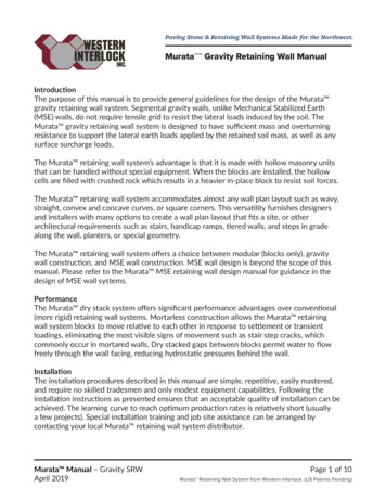
Example 1 Earthquake Load Combinations: Strength Design§1612.2 % &'& ! " # # This example demonstrates the application of the strength design load combinationsthat involve the seismic load E given in §1630.1.1. This will be done for the momentresisting frame structure shown below:Zone 4C a 0.44I 1.0ρ 1.1f 1 0.5Snow load S 0ABCDBeam A-B and Column C-D are elements of the special moment-resisting frame.Structural analysis has provided the following individual beam moments at A, and thecolumn axial loads and moments at C due to dead load, office building live load, andlateral seismic forces.Dead Load DBeam Moment at ALive Load LLateral Seismic Load Eh100 kip-ft50 kip-ft120 kip-ftColumn C-D Axial Load90 kips40 kips110 kipsColumn Moment at C40 kip-ft20 kip-ft160 kip-ftFind the following: Strength design moment at beam end A. Strength design axial load and moment at column top C.SEAOC Seismic Design Manual
Example 1 Earthquake Load Combinations: Strength Design§1612.2Calculations and Discussion Code ReferenceStrength design moment at beam end A.To determine strength design moments for design, the earthquake component E mustbe combined with the dead and live load components D and L . This process isillustrated below.Determine earthquake load E:The earthquake load E consists of two components as shown below inEquation (30-1). E h is due to horizontal forces, and E v is due to verticalforces.E ρE h E v§1630.1.1(30-1)The moment due to vertical earthquake forces is calculated asE v 0.5C a ID 0.5 (0.44 )(1.0)(100 ) 22 k - ft§1630.1.1The moment due to horizontal earthquake forces is given asE h 120 k - ftThereforeE ρE h E v 1.1(120) 22 154 k - ft Apply earthquake load combinations:The basic load combinations for strength design (or LRFD) are given in§1612.2.1. For this example, the applicable equations are:§1612.2.11.2 D 1.0 E f 1 L(12-5)0.9 D 1.0 E(12-6)Using Equation (12-5) and Equation (12-6), the strength design moment at Afor combined dead, live, and seismic forces are determined.M A 1.2 M D 1.0 M E f 1 M L 1.2 (100) 1.0 (154 ) 0.5 (50) 299 k - ftM A 0.9 M D 1.0M E 0.9 (100) 1.0 (154 ) 244 k - ft or 64 k - ft M A 299 k - ft or 64 k - ftSEAOC Seismic Design Manual
Example 1 Earthquake Load Combinations: Strength Design §1612.2Specific material requirements:There are different requirements for concrete (and masonry) frames than forsteel as follows.Structural Steel: Section 2210 specifies use of the load combinations of§1612.2.1 as given above without modification.Reinforced Concrete: Section 1909.2.3 specifies use of the loadcombinations of §1612.2.1, where Exception 2 requires the factor loadcombinations of Equation (12-5) and Equation (12-6) to be multiplied by 1.1for concrete and masonry elements. ( Note: At the time of publication, April1999, the 1.1 factor is under consideration for change to 1.0.) Therefore, for areinforced concrete frame, the combinations are:1.1 (1.2 D 1.0 E f 1 L ) 1.32 D 1.1E 1.1 f 1 L(12-5)1.1 (0.9 D 1.0E ) 0.99 D 1.1E(12-6)M A 1.1 (299 k - ft ) 328.9 k - ftM A 1.1 (244 k - ft or 64 k - ft ) 268.4 k - ft or 70.4 k - ft M A 328.9 k - ft or 70.4 k - ft for a concrete frame. Strength design axial load and moment at column top C.Determine earthquake load E:E ρE h E v§1630.1.1(30-1)whereE v 0.5C a ID 0.22 D§1630.1.1For axial loadE E h E v 1.1 (110 kips ) 0.22 (90 kips ) 140.8 kipsFor momentE E h E v 1.1 (160k - ft ) 0.22 (40k - ft ) 184.8 k - ftSEAOC Seismic Design Manual
Example 1 Earthquake Load Combinations: Strength Design§1612.2 Apply earthquake load combinations:§1630.1.11.2 D 1.0 E f 1 L(12-5)0.9 D 1.0 E(12-6)Design axial force PC at point C is calculated asPC 1.2 D 1.0 E f 1 L 1.2 (90) 1.0 (140.8) 0.5 (40) 268.8 kipsPC 0.9 D 1.0 E 0.9 (90 ) 1.0 (140.8) 221.8 and 59.8 kips PC 268.8 kips compression, or 59.8 kips tensionDesign moment M C at point C is calculated asM C 1.2 D 1.0 E f1L 1.2 (40 k - ft ) 1.0 (184.8 k - ft ) 0.5 (20 k - ft ) 242.8 k - ftM C 0.9 D 1.0 E 0.9 (40 k - ft ) 1.0(184.8 k - ft ) 220.8 k - ft or 148.8 k - ft M C 242.8 k-ft or –148.8 k-ftNote that the column section capacity must be designed for the interaction ofPC 268.8 kips compression and M C 242.8 k-ft (for dead, live andearthquake), and the interaction of PC 59.8 kips tension andM C 148.8 k-ft (for dead and earthquake). Specific material requirementsStructural Steel: Section 2210 specifies the use of the load combinations of§1612.2.1 as given above without modification.§1630.1.1Reinforced Concrete: The axial force PC and the moment M C must bemultiplied by 1.1 per §1612.2.1.CommentaryUse of strength design requires consideration of vertical seismic load E v . Whenallowable stress design is used, the vertical seismic load E v is not required under§1630.1.1. SEAOC Seismic Design Manual
Example 1 Earthquake Load Combinations: Strength Design§1612.2The incorporation of E v in the load combinations for strength design has the effectof increasing the load factor on the dead load action D. For example, consider theload combination of Equation (12-5)1.2 D 1.0 E ( f 1 L f 2 S )(12-5)where E ρE h E vand E v 0.5C a IDthis becomes1.2 D 1.0 (0.5C a ID ρ E h ) ( f 1 L f 2 S )(1.2 0.5C a I ) D 1.0ρ E h ( f 1 L f2S)in the numerical example0.5C a I 0.22Thus, the total factor on D is 1.2 0.22 1.42For the allowable stress design load combinations of §1612.3, E v may be taken aszero. When these combinations are converted to an equivalent strength design basis,the resulting factor on dead load D is comparable to (1.2 0.5C a I ) in §1612.2.For example, consider the following:The basic load combinations of §1612.3.1, without increase in allowable stresses,have a 1.70 factor on D (using the procedure permitted in §1630.8.2.1 for conversionto design strength).The alternate basic load combinations of §1612.3.2 with a permitted one-third1.70 1.28 factor on D.increase in allowable stress has a1.33SEAOC Seismic Design Manual
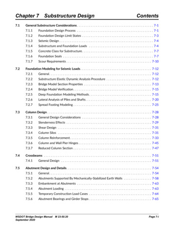
Example 2 Combinations of Loads§1612.3 & % &'(The code requires the use of allowable stress design for the design of wood membersand their fastenings (see §2301 and §2305). Section 1612.3 permits two differentcombinations of load methods. These are:1. Allowable stress design (ASD) of §1612.3.12. Alternate allowable stress design of §1612.3.2This example illustrates the application of each of these methods. This is done for theplywood shear wall shown below. The wall is a bearing wall in a light wood framedbuilding.The following information is given:Gravity loadsZone 4I 1.0ρ 1.0Ca 0.40V E 4.0 kips (seismic forcedetermined from §1630.2)VEPlywoodshear wallh 9'Hold-downGravity lo
The Seismic Design Manual was developed to fill a void that exists between the Commentary of the Blue Book, which explains the basis for the UBC seismic provisions, and everyday structural engineering design practice. The Seismic Design Manual illustrates how the provisions of the code are used . Volume I: Code