Transcription
Chapter 14Design of Structures with Seismic IsolationRonald L Mayes, Ph.D.Consulting Engineer, Berkeley, CaliforniaFarzad Naeim, Ph.D., S.E.Vice President and Director of Research and Development, John A. Martin and Associates, Inc., Los Angeles, California Key words:Base Isolation, Damage Control, Design Examples, Damping, Earthquake Engineering, Energy Dissipation,Feasibility of Isolation, Friction Devices, High-Damping rubber bearings, IBC-2000, Lead-Rubber Bearings,New Construction, Preliminary Design, Response Spectrum Analysis, Seismic Isolation, SeismicRehabilitation, Static Analysis, Time-History Analysis.Abstract:This chapter surveys the principles, benefits, and the feasibility of seismic isolation. The basic principles ofseismic isolation are introduced first. Contrary to a perception held by many engineers, neither the conceptof seismic isolation is new nor its application is necessarily complex. What is new is the availability ofrelatively new materials and devices worked to perfection over the last two decades and advances incomputational techniques now commonly in use by practicing engineers. Force-deflection characteristics otcommonly used isolation devices are introduced next followed by guidelines for evaluation of the feasibilityof seismic isolation as an alternative for a given project. The differences in approach to new constructionand rehabilitation of existing structures are highlighted. The building code provisions for seismic isolationare covered next. The very recently released year 2000 edition of the International Building Code (IBC2000) takes a much more simple approach to seismic isolation than did its direct predecessor, the 1997edition of the Uniform Building Code (UBC-97). This is true even though the theory and objectivesimplemented in both of these codes are the same. The simplification is largely due to incorporation ofspectral hazard maps in IBC-2000. A very practical side-effect of this incorporation is elimination of nearfault factors from the design process simply because now they are explicitly contained in the map. In manycases, design according to the new IBC-200 requirements will result in smaller displacement and forcedemands on the isolation system and the structure above the isolation plane. This in terms mean that seismicisolation can be implemented much more economically than it was possible under UBC-97. The IBC-2000design provisions for seismic isolation are discussed in detail. A simple preliminary design procedure isprovided to aid engineers in initial sizing of the isolation devices. Several examples are provided to illustratethe practical application of the material covered in this chapter.723
724Chapter 14
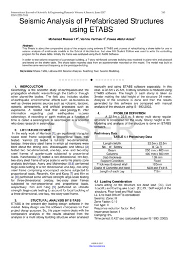
14. Design of Structures with Seismic Isolation14.1INTRODUCTIONBecause of today’s concern for liability,engineering innovations must be exhaustivelytested and analytically proven to a degreeunknown in the past. Early engineers wererespected for their ability to design from firstprinciples and produce designs that wereconceptually right even though analytical orlaboratory methods did not exist that wouldremove all doubt. For the most part, the greatearly engineers removed doubt by force of theirpersonality and confidence. They took risks thatwould be unthinkable today.The field of seismic design is, as perhapsbenefits a subject directly concerned with bothlife safety and uncertainty, cautious and slow toinnovate. In practice, improved seismic designdoes not represent a market opportunitybecause seismic safety is generally taken forgranted. Like other code-dominated issues, andlike airplane safety, seismic safety has neverbeen much of a selling point. Money diverted toimprove seismic resistance is often seen as adetraction from more visible and enjoyableattributes.Improvements in seismic safety, since aboutthe time of the San Francisco earthquake of1906, have been due primarily to acceptance ofever-increasing force levels to which buildingsmust be designed. Innovation has beenconfirmed to the development and acceptanceof economical structural systems that performreasonably well, accommodate architecturaldemands such as open exteriors and the absenceof interior walls, and enable materials such assteel and reinforced concrete to compete in themarketplace on near-equal terms.The vocabulary of seismic design is limited.The choices for lateral resistance lie amongshear walls, braced frames, and momentresistant frames. Over the years, these havebeen refined and their details developed, andmethods of analysis and modeling haveimproved and reduced uncertainty. But thebasic approach has not changed: construct aductile and/or strong building and attach itsecurely to the ground. This approach of arm725wrestling with nature is neither clever ough codes have mandated steadilyincreasing force levels, in a severe earthquake abuilding, if it were to remain elastic, would stillencounter forces several times above itsdesigned capacity. This situation is quitedifferent from that for vertical forces, in whichsafety factors insure that actual forces will notexceed 50% of designed capacity unless aserious mistake has been made. For verticalforces, this is easy to do. But to achieve similarperformance for seismic forces, the structurewould be unacceptably expensive and itsarchitectural impact would be extreme. Thisdiscrepancy between seismic demand andcapacity is traditionally accommodated byreserve capacity, which includes uncalculatedadditional strength in the structure and often thecontribution of portions and exterior cladding tothe strength and stiffness of the building. Inaddition, the ability of materials such as steel todissipate energy by permanent deformation—which is called ductility—greatly reduces thelikelihood of total collapse.Modern buildings contain extremelysensitive and costly equipment that havebecome vital in business, commerce, educationand health care. Electronically kept records areessential to the proper functioning of oursociety. These building contents frequently aremore costly and valuable than the ation and emergency centres, andpolice and fire stations must be operationalwhen needed most: immediately after anearthquake.Conventional construction can cause veryhigh floor accelerations in stiff buildings andlarge interstory drifts in flexible structures.These two factors cause difficulties in insuringthe safety of the building components andcontents (Figure 14-1).In the past decade, an alternative to thebrute-force to nature has finally reached thestage of more widespread application. Thisapproach is obvious and easily explainable at
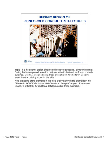
726Chapter 14the cocktail-party level: why not detach thebuilding from the ground in such a way that theearthquake motions are not transmitted upthrough the building, or are at least greatlyreduced? This conceptually simple idea hasrequired much research to make it feasible, andonly with modern computerized analysis hasbecome possible. Application has depended onvery sophisticated materials research into bothnatural and composite materials in order toprovide the necessary performance.thereby providing protection to the buildingcontents and components (Figure 14-2).Figure 14-2. Base Isolated StructureFigure 14-1. Conventional StructureThis new concept, now generally termedseismic isolation, meets all the criteria for aclassic modern technological innovation.Imaginative advances in conceptual thinkingwere necessary, as were materials new to theindustry,andideashavedevelopedsimultaneously on a worldwide basis. But themethod threatens conventional and establisheddesign procedures, so the road to seismicisolation innovation is paved with argument,head shaking, and bureaucratic caution—all, tosome extent, well-intentioned and necessary,given our litigious society.Mounting buildings on an isolation systemwill prevent most of the horizontal movementof the ground from being transmitted to thebuildings. This results in a significant reductionin floor accelerations and interstory drifts,The principle of seismic isolation is tointroduce flexibility at the base of a structure inthe horizontal plane, while at the same timeintroducing damping elements to restrict theamplitude of the motion caused by theearthquake. The concept of isolating structuresfrom the damaging effects of earthquakes is notnew. The first patent for a seismic isolationscheme was taken out in 1909(14-1) and sincethat time several proposals with similarobjectives have been made (see References 142 to 14-8). Nevertheless, until the last twodecades, few structures have been designed andbuilt using these principles.However, new impetus was given to theconcept of seismic isolation by the successfuldevelopment of mechanical-energy dissipatersand elastomers with high damping properties(see References 14-8 to 14-15). Mechanicalenergy dissipaters, when used in combinationwith a flexible isolation device, can control theresponse of the structure by limitingdisplacements and forces, thereby significantlyimproving seismic performance. The seismicenergy is dissipated in components specificallydesigned for that purpose, relieving structuralelements, such as beams and columns, fromenergy-dissipation roles (and thus damage).There are over two hundred civil engineeringstructures that have now been constructed using
14. Design of Structures with Seismic Isolationthe principles of seismic isolation. Kelly(14-6),Buckle and Mayes(14-7) and Naeim and Kelly(14-8)provide an excellent history of world overview.Other references containing overview materialare given in references 14-25 and 14-41.The advantages of seismic isolation includethe ability to eliminate or very significantlyreduce structural and nonstructural damage, toenhance the safety of the building contents andarchitectural facades, and to reduce seismicdesign forces. These potential benefits aregreatest for stiff structures fixed rigidly to theground, such as low- and medium-risebuildings, nuclear power plants, bridges, andmany types of equipment. Some tectonic andsoil-foundation conditions may, however,preclude the use of seismic isolation.14.1.1An Idea Whose Time Has ComeThe elastomeric bearing and the mechanicaldamper are fundamental components in manyseismic isolation schemes. But it is not just theinvention of the elastomeric bearing and theenergy dissipater which has made seismicisolation a practical reality. Three other parallel,but independent, developments have alsocontributed to its success.The first of these was the development ofreliable software for the computer analysis ofstructures so as to predict their performance anddetermine design parameters. Work has been inprogress for more than 25 years on the softwarefor inelastic analysis of structural systems, andthere are many available programs. htforward, and correlation studies withmodel tests show many software systems to besoundly based.The second development was the use ofshaking tables which are able to simulate theeffects of real recorded earthquake groundmotions on different types of structures. Theresults of shaking-table tests over the last 20years (see Reference 14-16 to 14-22 and 14-31to 14-40) have provided another mechanism toenhance confidence in the way buildingsrespond during real earthquakes. In addition,727the results provide an opportunity to validatecomputer modeling techniques which are thenused on full-size structures.A third important development is in the skillof the engineering seismologist in estimatingground motions at a particular site. Recentadvances in seismology have given moreconfidence in site-specific ground motionswhich take into account fault distances, localand global geology, and return periods. Thesedesign motions are basic input to the computermodeling of seismically isolated systems andare a vital step in the estimation of systemperformance.In summary then, five recent developmentsare together responsible for elevating seismicisolation from fantasy to practical reality:The design and manufacture of high-qualityelastomeric (rubber) pads, frequently calledbearings, that are used to support the weight ofthe structure but at the same time protect it fromearthquake-induced forces.The design and manufacture of mechanicalenergy dissipaters (absorbers) and highdamping elastomers that are used to reduce themovement across the bearings to practical andacceptable levels and to resist wind loads.The development and acceptance ofcomputer software for the analysis ofseismically isolated structures which includesnonlinear material properties and the timevarying nature of the earthquake loads.The ability to perform shaking-table testsusing real recorded earthquake ground motionsto evaluate the performance of structures andprovide results to validate computer modelingtechniques.The development and acceptance ofproceduresforestimatingsite-specificearthquake ground motions for different returnperiods.14.2CONSIDERATIONS FORSEISMIC ISOLATIONThe need for seismic isolation of a structuremay arise if any of the following situationsapply:
728– Increased building safety and postearthquake operability are desired.– Reduced lateral design forces are desired.– Alternate forms of construction with limitedductility capacity (such as precast concrete)are desired in an earthquake region.– An existing structure is not currently safefor earthquake loads.For new structures current building codesapply in all seismic zones, and therefore manydesigners may feel that the need for seismicisolation does not exist because the coderequirements can be satisfied by currentdesigns. Code designs, however, are generallycontrolled by a design philosophy whichproduces structures which are much more proneto damage than their seismic isolatedcounterparts. A typical building code statementof philosophy(14-23) states that buildingsdesigned in accordance with its provisions will– resist minor earthquakes without damage,– resist moderate earthquakes withoutstructural damage but with somenonstructural damage,– resist major earthquakes without collapsebut with structural and nonstructuraldamage.These principles of performance also applyto conventional buildings that are rehabilitatedto code-level design forces.Seismic isolation promises the capability ofproviding a building with better performancecharacteristics than our current code approachtowards conventional buildings and thusrepresents a major step forward in the seismicdesign of civil engineering structures. In thecase of a building retrofit, the need for isolationmay be obvious: the structure may simply notbe safe in its present condition should anearthquake occur. In such cases, if seismicisolation is suitable, its effectiveness comparedwith alternative solutions such as strengtheningshould be examined.Chapter 1414.2.1Solutions for NonstructuralDamageOne of the more difficult issues to addressfrom a conventional design viewpoint is that ofreducing nonstructural and building-contentdamage. This is very often ignored, and whenaddressed, can be very expensive to incorporatein conventional design. In fact, the cost ofsatisfying the more stringent bracingrequirements of nonstructural elements in aCalifornia hospital is on the order of 2 to 4per square foot more than for ordinarycommercial buildings.There are two primary mechanisms thatcause nonstructural damage. The first is relatedto interstory drift between floors, and thesecond to floor accelerations. Interstory drift isdefined as the relative displacement that occursbetween two floors divided by the story ns that occur as a result of theearthquake, and in conventional constructionthey generally increase up the height of thebuilding. Together, these two components causedamage to the building contents, architecturalfacades, partitions, piping and ductwork,ceilings, building equipment, and elevators(Figure 14-1).Clearly, a design concept that reduces bothinterstory drifts and floor accelerationscombines the best aspects of these two currentdesign philosophies. Seismic isolation is such aconcept (Figure 14-2), since it can significantlyreduce both floor accelerations and interstorydrift and thus provide a viable economicsolution to the difficult problem of reducingnonstructural earthquake damage.14.3BASIC ELEMENTS OFSEISMIC ISOLATIONSYSTEMSThere are three basic elements in anypractical seismic isolation system. These are:
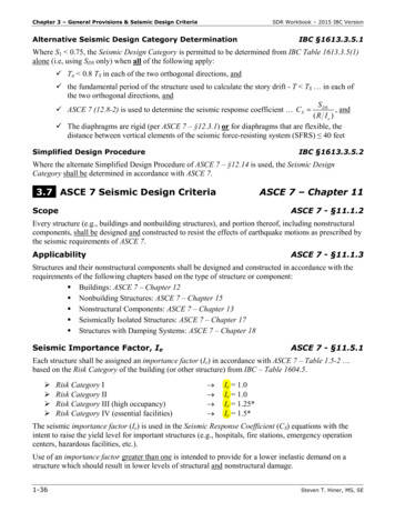
14. Design of Structures with Seismic Isolation1. a flexible mounting so that the period ofvibration of the total system is lengthenedsufficiently to reduce the force response;2. a damper or energy dissipater so that therelative deflections between building andground can be controlled to a practicaldesign level; and3. a means of providing rigidity under low(service) load levels such as wind and minorearthquakes.Bridge structures have for a number of yearsbeen supported on elastomeric bearings(14-24),and as a consequence have already beendesigned with a flexible mount. It is equallypossible to support buildings on elastomericbearings, and numerous examples exist wherebuildings have been successfully mounted onpads. To date this has been done more forvertical-vibration isolation rather than seismicprotection. Over 100 buildings in Europe andAustralia have been built on rubber bearings toisolate them from vertical vibrations fromsubway systems below, and are performing wellmore than 40 years after construction. Byincreasing the thickness of the bearing,additional flexibility and period shift can beattained.While the introduction of lateral flexibilitymay be highly desirable, additional verticalflexibility is not. Vertical rigidity is maintainedby constructing the rubber bearing in layers andsandwiching steel shims between layers. Thesteel shims, which are bonded to each layer ofrubber, constrain lateral deformation of therubber under vertical load. This results invertical stiffness and of a similar order ofmagnitude to conventional building columns.An elastomeric bearing is not the only meansof introducing flexibility into a structure, but itappears to be one of the most practicalapproaches. Other possible devices includerollers, friction slip plates, capable suspension,sleeved piles, and rocking (stepping)foundations (Figures 14-3 to 14-7). The mostpopular devices for seismic isolation ofbuildings in the United States are the leadrubber bearings, high-damping rubber bearingsand the friction pendulum system (Figure 14-8).729Figure 14-3.Elastomeric bearingsFigure 14-4. RollersFigure 14-5. Sleeved PilesFigure 14-6. RockingFigure 14-7. Cable SuspensionThe reduction in force with increasing period(flexibility) is shown schematically in the forceresponse curve of Figure 14-9. Substantialreductions in base shear are possible if theperiod of vibration of the structure issignificantly lengthened.
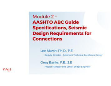
730Chapter 14S u p erstru ctu reA n ch o rP ierA n ch o rE lasto m ericB earin gof the sensitivity to variations in ground motioncharacteristics, as indicated by the smootherforce response curves at higher damping levels.Care must be taken, however, not to induceexcessive damping into the system because thatcould produce story accelerations difficult topin down in an ordinary dynamic analysis.S u p erstru ctu reA n ch o rP ierA n ch o rE lasto m ericB earin gS p h ericalC o n cav eS u rfaceL eadA rticu latedS lid erFigure 14-9. Idealized force response spectrumP T F E B earin gM aterialFigure 14-8. Most popular building isolation devices(Top: the high damping rubber device; Middle: the leadrubber device; Bottom: the friction pendulum device).The reduction in force response illustrated inFigure 14-9 is primarily dependent on thenature of the earthquake ground motion and theperiod of the fixed-base structure. Further, theadditional flexibility needed to lengthen theperiod of the structure will give rise to largerelative displacements across the flexiblemount. Figure 14-10 shows an idealizeddisplacement response curve from whichdisplacements are seen to increase withincreasing period (flexibility). However, asshown in Figure 14-11, if substantial additionaldamping can be introduced into the structure,the displacement problem can be controlled. Itis also seen that increasing the damping reducesthe forces at a given period and removes muchFigure 14-10. Idealized displacement response spectrumEnergy Dissipation One of the mosteffective means of providing a substantial levelof damping is through hysteretic energydissipation. The term “hysteric” refers to theoffset in the loading and unloading curvesunder cyclic loading. Work done during loadingis not completely recovered during unloading,and the difference is lost (dissipated) as heat.Figure 14-12 shows an idealized forcedisplacement loop, where the enclosed area is a
14. Design of Structures with Seismic Isolation731Figure 14-12. Response spectra for increasing dampingmeasure of the energy dissipated during onecycle of motion. Mechanical devices which usefriction or the plastic deformation of either mildsteel or lead to achieve this behavior have beendeveloped (14-9 to 14-14), and several mechanicalenergy dissipation devices developed in NewZealand are shown in Figure 14-13.Figure 14-11. Hysteretic force-deflection curveMany engineering materials are hysteretic bynature, and all elastomers exhibit this propertyto some extent. By the addition of specialpurpose fillers to elastomers, it is possible toincrease their natural hysteresis without undulyaffecting their mechanical properties(14-10). Sucha technique gives a useful source of damping,but so far it has not been possible to achieve thesame level of energy dissipation as is possiblewith, say, a lead-rubber elastomeric bearing orsupplemental viscous dampers.Friction is another source of energydissipation which is used to limit deflections.However, with the exception of the frictionpendulum system, it can be a difficult source toquantify. A further disadvantage is that mostfrictional devices are not self-centering, and apermanent offset between the sliding parts mayresult after an earthquake. The frictionpendulum system overcomes this problem byusing a curved rather than flat surface on whichthe friction occurs. In proportioning a leadrubber system or a friction pendulum systemcare must be exercised in design to ensure thatthe restoring force during expected seismicevents would overcome the resistance of thedevice to self-centering. In practice it iscommon to compliment lead-rubber bearingswith ones without a lead core and this approachhas proved to be very successful.Hydraulic damping has been usedsuccessfully in some bridges and a few specialpurpose structures(14-7). Potentially highdamping forces are possible from viscous fluidflow, but maintenance requirements and highinitial cost have restricted the use of suchdevices.Rigidity for low lateral loads and flexibilityfor high seismic loads is very desirable. It isclearly undesirable to have a structural system
732Chapter 14Figure 14-13. Various mechanical energy dissipaterswhich will vibrate perceptibly under frequentlyoccurring loads such as minor earthquakes orwind loads.Lead-rubber bearings, well designed highdamping rubber bearings, as well as othermechanical-energy dissipaters provide thedesired low load rigidity by virtue of their highelastic stiffness (Figure 14-14). Some otherseismic isolation systems require a windrestraint device for this purpose—typically arigid component designed to fail under a givenlevel of lateral load. This can result in a shockloading being transferred to the structure due tothe sudden loss of load in the restraint.Nonsymmetrical failure of such devices canalso introduce undesirable torsional effects in a
14. Design of Structures with Seismic Isolationbuilding. Further, such devices will need to bereplaced after each failure.Table 14-1 summarizes the sources offlexibility that have been discussed above. Amore detailed explanation of these concepts canbe found in the proceedings of two workshopson base Isolation and Passive EnergyDissipation that have been conducted byApplied Technology Council(14-25 and 14-41) aswell as a recent textbook by Naeim andKelly(14-8).Figure 14-14. Idealized force-displacement relationshipsfor isolation systemsTable 14-1. Alternative Sources of Flexibility and EnergyDissipationFlexible Mounting SystemsUnreinforced rubber blocksElastomeric bearings(reinforced rubber blocks)Sliding platesRoller and / or ball bearingsSleeved pilesRocking systemsSuspended floorsAir cushionsSlinky springsDamping Devices/ MechanismsPlastic deformation of a metalFrictionHigh-damping elastomersViscous fluid dampingTuned mass ptually, there are four basic types offorce-deflection relationships for isolationsystems. These idealized relationships areshown in Figure 14-15, with each idealizedcurve having the same design displacement Dfor the design-level earthquake.A linear isolation system is represented bycurve A and has the same isolated period for allearthquake load levels. In addition, the forcegenerated in the superstructure is directlyproportional to the displacement across theisolation system. A linear isolation system willrequire some form of wind-restrainingmechanism to be added to the system.A hardening isolation system is representedby curve B. This system is soft initially (longeffective period) and then stiffness (effectiveperiod shortens) as the earthquake load levelincreases. When the earthquake load levelinduces displacements in excess of the designdisplacement in a hardening system, thesuperstructure is subjected to higher forces andthe isolation system to lower displacementsthan in a comparable linear system. Like alinear system, a hardening system will alsorequire some form of additional windrestraining mechanism.A softening isolation system is representedby curve C. This system is stiff initially (shorteffective period) and softens (effective periodlengthens) as the earthquake load level inducesdisplacements in excess of the designdisplacement in a softening system, thesuperstructure is subjected to lower forces andthe isolation system to higher displacementsthan in a comparable linear system. The highinitial stiffness of a softening system is thewind-restraining mechanism.A flat sliding isolation system is representedby curve D. This system is governed by thefriction force of the isolation system. As in thesoftening system, the effective period lengthensas the earthquake load level increases, and theloads of the superstructure remain constant. Thedisplacement of the sliding isolation system
734Chapter 14Figure 14-15. Design principles of seismic isolationafter repeated earthquake cycles is highlydependent on the vibratory characteristics of theground motion and may exceed the designdisplacement. Consequently, minimum designrequirements do not adequately define the peakseismic displacement for seismic isolationsystems governed solely by friction forces. Thevalue of the coefficient must be high enough toresist the wind forces.14.5SEISMIC-ISOLATIONDESIGN PRINCIPLESThe design principles for seismic isolationare illustrated in Figure 14-16. The top curve ofthis figure shows the realistic forces based on a5% ground response spectrum which will beimposed on a non-isolated structure fromtypical code forces(14-28). The spectrum shown isfor a rock site if the structure has sufficientelastic strength to resist this level of load. Thelowest curve shows the forces which a typicalcode(14-28) requires a structure to be designedfor, and the second-lowest curve shows theprobable strength assuming the structure isdesigned for the corresponding code forces. Theprobable strength is typically about 1.5 to 2.0times higher than the design strength because ofthe design load factors, actual material strengthswhich are greater in practice than thoseassumed for design, conservatism in structuraldesign, and other factors. The differencebetween the maximum elastic force and theprobable yield strength is an approximateindication of the energy which must beabsorbed by ductility in the structural elements.When a building is isolated, the maximumelastic forces are reduced considerably due toperiod shift and energy dissipation, as shown in
14. Design of Structures with Seismic IsolationFigures 14-10 and 14-12. The elastic forces ona seismically isolated structure are shown bythe dashed curve in Figure 14-16. This curvecorresponds to a system with as high as 30%equivalent viscous damping.(14-29)If a stiff building, with a fixed-basefundamental period of 1.0 sec or less, isisolated, then its fundamental period will beincreased into the 1.5- to 2.5-sec range (Figure14-10). This results in a reduced code designforce (Figure 14-16), but more importantly inthe 1.5- to 2.5-sec range the probable yieldstrength of the isolated building isapproximately the same as the maximum forcesto which it will be subjected. Therefore, therewill be little or no ductility demand on thestructural system, and the lateral design forcescan be theoretically reduced by approximately50%, if the building code permits such areduction.14.6FEASIBILITY OF SEISMICISOLATIONStructures are generally suitable for seismicisolation if the following conditions exist:– The subsoil does not produce apredominance of long period ground motionsuch as that obtained in Mexico City.– The structure has two stories or more (or isunusually heavy).– The site permits horizontal displacements atthe base of the order of 8 in. or more.– The structure is fairly squat.– Wind lateral loads and other non-earthquakeload are less than approximately 10% of theweight of the structure.Each project must be assessed individuallyand early in the design phase to determine itssuitability for
of seismic isolation as an alternative for a given project. The differences in approach to new construction and rehabilitation of existing structures are highlighted. The building code provisions for seismic isolation are covered next. The very recently released year 2000 edition