Transcription
Chapter 66-1Seismic DesignSeismic Design Responsibility and Policy6-1.1 Responsibility of the Geotechnical DesignerThe geotechnical designer is responsible for providing geotechnical/seismic inputparameters to the structural engineers for their use in structural design of thetransportation infrastructure (e.g., bridges, retaining walls, ferry terminals, etc.). Specificelements to be addressed by the geotechnical designer include the design ground motionparameters, site response, geotechnical design parameters, and geologic hazards. Thegeotechnical designer is also responsible for providing input for evaluation of soilstructure interaction (foundation response to seismic loading), earthquake-induced earthpressures on retaining walls, and an assessment of the impacts of geologic hazards onthe structures.6-1.2 Geotechnical Seismic Design Policies6-1.2.1Seismic Performance ObjectivesIn general, the AASHTO Load and Resistance Factor Design (LRFD) Bridge DesignSpecifications is followed for structure classification of bridges, except that thedesignation “other” is replaced with “normal” in the WSDOT Bridge Design Manual LRFD(BDM) M 23-50.In keeping with the current seismic design approaches employed both nationally andinternationally, geotechnical seismic design shall be consistent with the philosophyidentified in the WSDOT BDM for structure seismic design which defines the structureperformance objectives for the Safety Evaluation Earthquake (SEE) and the FunctionalEvaluation Earthquake (FEE). For the SEE, the performance objective requires thatthe structure be designed for non-collapse due to earthquake shaking and geologichazards associated with a design seismic event so that loss of life and serious injurydue to structure collapse are minimized. This is the primary performance objectivefor bridges classified as “normal”. This performance objective shall be achieved at aseismic hazard level that is consistent with the seismic hazard level required in theAASHTO specifications (e.g., 7 percent probability of exceedance in 75 years for otherstructures, which is an approximate return period of 1,000 years). Geotechnical designassociated with structures shall be consistent with this performance objective and designhazard level.For the FEE, the performance objective requires minimal to no earthquake damage andthat the structure remain in full service after the earthquake. For bridges classified as“essential” or “critical”, a two level seismic design is required: the SEE as defined above,except that the damage due to the earthquake is limited to minimal to moderate andlimited service for the structure is expected after the earthquake, and the FunctionalEvaluation Earthquake (FEE). This FEE performance objective shall be achieved at ahazard level of 30 percent probability of exceedance in 75 years (or 210-year returnperiod). Geotechnical design associated with structures shall also be consistent withthis performance objective and design hazard level for essential and critical bridges. Seethe BDM Chapter 4, for additional details regarding the performance objectives andGeotechnical Design Manual M 46-03.12July 2019Page 6-1
Chapter 6Seismic Designassociated design requirements. See GDM Section 6-3.1 for requirements to assess thehazard level.Bridge approach embankments and fills through which cut-and-cover tunnels areconstructed should be designed to remain stable during the design seismic event becauseof the potential to contribute to collapse or inadequate performance of the structureshould they fail or deform excessively. The aerial extent of approach embankment(and embankment surrounding cut-and-cover tunnels) seismic design and mitigation (ifnecessary) should be such that the structure is protected against instability or loadingconditions that could result in collapse or inadequate performance. The typical distance ofevaluation and mitigation is within 100 feet of the abutment or tunnel wall, but the actualdistance should be evaluated on a case-by-case basis. Instability or other seismic hazardssuch as liquefaction, lateral spread, downdrag, and settlement may require mitigationnear the abutment or tunnel wall to ensure that the structure is not compromised duringa design seismic event. The geotechnical designer should evaluate the potential fordifferential settlement between mitigated and non mitigated soils. Additional measuresmay be required to limit differential settlements to tolerable levels both for static andseismic conditions. For “normal” bridges, the seismic stability of the bridge approachembankment in the lateral direction may not be required if instability in the lateraldirection will not significantly damage the bridge and will not cause a life safety issue.The bridge interior pier foundations should also be designed to be adequately stable withregard to liquefaction, lateral spreading, flow failure, and other seismic effects to preventbridge collapse for “normal” bridges when considering the FEE and which otherwise couldcompromise the functioning of essential and critical bridges for both the SEE and FEEhazard levels.All retaining walls and abutment walls, including reinforced slopes steeper than 0.5H:1V,which shall be considered to be a wall (see Section 15-5.6), shall be evaluated anddesigned for seismic stability internally and externally (i.e. sliding, eccentricity, and bearingcapacity), with the exception of walls that meet the AASHTO LRFD Bridge Design Manual“No Seismic Analysis” provisions in AASHTO Article 11.5.4.2. Noise walls, as well asreinforced slopes steeper than 1.2H:1V, shall also be evaluated for seismic stability.With regard to seismic overall slope stability (often referred to as global stability) involvinga retaining wall/reinforced slope as defined above, or noise wall, the geotechnicaldesigner shall evaluate the impacts of failure due to seismic loading, as well as forliquefied conditions after shaking. If the wall seismic global stability does not meet therequirements in Sections 6-4.2 and 6-4.3, collapse of the wall/reinforced slope or noisewall shall be considered likely and assumed to cause loss of life or severe injury to thepublic if the following are true: The maximum wall/reinforced slope height is greater than 10 feet in height and The wall/reinforced slope is close enough to the traveled way such that collapse ofthe wall/reinforced slope or the slope that it supports will cause an abrupt elevationchange within part or all of the traveled way, or will result in debris from the collapsedwall and the material that it supports being deposited on part or all of the traveledway, or other adjacent facility/structure.If the above two bullets are true, the stability of the wall/reinforced slope or noise wallshall be improved such that the life safety of the public is preserved. If the maximum wall/reinforced slope or noise wall or noise wall height is less than 10 ft, but the second bulletPage 6-2Geotechnical Design Manual M 46-03.12July 2019
Seismic DesignChapter 6is still true, the potential for wall/reinforced slope collapse shall be evaluated to assessthe severity of the impact to the traveled way and to the potential for life safety issuesto occur. Similarly, if the wall height is greater than 10 ft, but it is not near the traveledway as defined above, the potential for wall/reinforced slope or noise wall collapse shallbe evaluated to assess the severity of the impact to the public and the potential for lifesafety issues to occur. In either of these cases, if it is determined that failure of the wallwill compromise the life safety of the public, the stability of the wall/reinforced slope ornoise wall shall be improved such that the life safety of the public is preserved.Note that the policy to stabilize retaining walls/reinforced slopes and noise walls foroverall stability due to design seismic events may not be practical for walls/reinforcedslopes or noise walls placed on marginally stable landslide areas or otherwise marginallystable slopes. In general, if the placement of a wall/reinforced slope within a marginallystable slope (i.e., marginally stable for static conditions) has only a minor effect on theseismic stability of the landslide or slope, or if the wall/reinforced slope has a relativelylow risk of causing loss of life or severe injury to the traveling public if collapse occurs,the requirement of the wall/reinforced slope and slope above and/or below the structureto meet minimum seismic overall stability requirements may be waived, subject to theapproval of the State Geotechnical Engineer. The State Geotechnical Engineer willassess the impact and potential risks caused by wall and slope seismic instability or poorperformance, and the magnitude of the effect the presence of the wall/reinforced slopecould have on the stability of the overall slope during the design seismic event. Theeffect on the corridor in addition to the portion of the corridor being addressed by theproject will be considered. In general, if the presence of the wall/reinforced slope coulddecrease the overall slope stability factor of safety by more than 0.05, the requirement tomeet minimum seismic overall slope stability requirements will not be waived. However,this requirement may be waived by the State Geotechnical Engineer if the seismic slopestability safety factor for the existing slope (for the design earthquake ground motion) issignificantly less than 0.9, subject to the evaluation of the impacts described above.Cut slopes in soil and rock, fill slopes, and embankments should be evaluated forinstability due to design seismic events and associated geologic hazards. Instabilityassociated with cuts and fills is usually not mitigated due to the high cost of applyingsuch a design policy uniformly to all slopes statewide. However, slopes that could causecollapse of an adjacent structure (e.g., a bridge, building, or pipeline) if failure due toseismic loading occurs, shall be stabilized.6-1.2.2Liquefaction Mitigation for Bridge WideningsBridge widenings require special considerations, as the existing bridge to be widened maynot be adequately stabilized to resist the forces imparted to the bridge due to liquefactioneffects such as downdrag and lateral spreading loads/deformations. See BDM Section 4.3for bridge widening seismic design and existing bridge seismic retrofit policies.To assess the effect of liquefaction induced foundation loading and deformation on theexisting and widened bridge stability, the geotechnical engineer provides the structuralengineer with the following: depth and extent of soil that is likely to liquefy for the applicable hazard level (i.e.,for the SEE for normal bridges, and the SEE and FEE hazard levels for essential andcritical bridges,Geotechnical Design Manual M 46-03.12July 2019Page 6-3
Chapter 6Seismic Design liquefaction induced downdrag loads and settlement, p-y curve parameters for the soil in both a liquefied and not liquefied state, the lateral spreading soil deformation profile (i.e., free field displacements), and the lateral loads acting on the foundation elements if flow failure is likely.With this information, the structural designer can then determine the seismic stabilityof the existing bridge and bridge widening, and the need for structural strengthening ofthe existing bridge. If that is not feasible, the geotechnical engineer assesses the need forground improvement to prevent the liquefaction from occurring. If ground improvement isneeded, the geotechnical engineer also provides a ground improvement design.Note that the foundation loads caused by flow failure are affected by the foundationdetails and therefore may require some design iteration between the geotechnical andstructural designer.Details on the liquefaction analysis, mitigation needed if the bridge cannot be designed toresist the forces and soil deformation anticipated, and the input the geotechnical designerprovides to the structural designer regarding liquefaction and its effect, are provided inSections 6-4.2 and 6-5 of this GDM.6-1.2.3Maximum Considered Depth for LiquefactionWhen evaluating liquefaction potential and its impacts to transportation facilities, themaximum considered liquefaction depth below the natural ground surface shall be limitedto 80 feet. However, for sites that contain exceptionally loose soils that are apparentlyhighly susceptible to liquefaction to greater depths, effective stress analysis techniquesmay be used to evaluate the potential for deeper liquefaction and the potential impacts ofthat liquefaction. The reasons for this depth limitation are as follows:Limits of Simplified Procedures – The simplified procedures most commonly usedto assess liquefaction potential are based on historical databases of liquefied siteswith shallow liquefaction (i.e., in general, less than 50 feet). Thus, these empiricalmethodologies have not been calibrated to evaluate deep liquefaction. In addition,the simplified equation used to estimate the earthquake induced cyclic shear stressratio (CSR) is based on a stress reduction coefficient, rd, which is highly variable atdepth. For example, at shallow depth (15 feet), rd ranges from about 0.94 to 0.98. Asdepth increases, rd becomes more variable ranging, for example, from 0.40 to 0.80 ata depth of 65 feet. The uncertainty regarding the coefficient rd and lack of verificationof the simplified procedures used to predict liquefaction at depth, as well as some ofthe simplifying assumptions and empiricism within the simplified method with regardto the calculation of liquefaction resistance (i.e., the cyclic resistance ratio CRR), limitthe depth at which these simplified procedures should be used. Therefore, simplifiedempirical methods to predict liquefaction at depths greater than 50 to 60 feet shouldbe based on a site response analysis to obtain an appropriate, site-specific stressreduction profile, provided that sufficient subsurface data are available and thatvariability in the input ground motions is considered.Page 6-4Geotechnical Design Manual M 46-03.12July 2019
Seismic DesignGeotechnical Design Manual M 46-03.12July 2019Chapter 6Page 6-5
Chapter 6Seismic DesignUntil the AASHTO Guide Specifications for LRFD Bridge Seismic Design are fully adopted inthe AASHTO LRFD Bridge Design Specifications, the seismic design provisions in the GuideSpecifications regarding foundation design, liquefaction assessment, earthquake hazardassessment, and ground response analysis shall be considered to supersede the parallelseismic provisions in the AASHTO LRFD Bridge Design Specifications.With regard to seismic hazard levels, the AASHTO Guide Specifications for LRFD SeismicBridge Design and the AASHTO LRFD Bridge Design Specifications are based on the2002 USGS website hazard model at a return period of 975 years (i.e., a probability ofexceedance of approximately 7 percent in 75 years). The GDM and BDM seismic designrequirements have been updated to use the 2014 USGS website hazard model at aprobability of exceedance of 7 percent in 75 years and shall be considered to supersedethe AASHTO specifications. Note that the USGS website refers to this hazard level as 5%in 50 years.For seismic design of new buildings and non-roadway infrastructure, the InternationalBuilding Code (IBC) (International Code Council), most current version should be used.FHWA geotechnical design manuals, or other nationally recognized design manuals, areconsidered secondary relative to this WSDOT GDM and the AASHTO manuals (and forbuildings, the IBC) listed above regarding WSDOT geotechnical seismic design policy,and may be used to supplement the WSDOT GDM, WSDOT BDM, and AASHTO designspecifications.A brief description of these additional references is as follows:FHWA Geotechnical Engineering Circular No. 3 (Kavazanjian, et al., 2011) – ThisFHWA document provides design guidance for geotechnical earthquake engineeringfor highways. Specifically, this document provides guidance on earthquakefundamentals, seismic hazard analysis, ground motion characterization, sitecharacterization, seismic site response analysis, seismic slope stability, liquefaction,and seismic design of foundations and retaining walls. The document also includesdesign examples for typical geotechnical earthquake engineering analyses.FHWA LRFD Seismic Analysis and Design of Bridges Reference Manual (Marsh et al.,2014) – This manual adapts and updates FHWA Geotechnical Engineering CircularNo. 3 to be applicable to LRFD for Bridges and their foundations. This manual includesboth geotechnical and structural design.Geotechnical Earthquake Engineering Textbook – The textbook titled GeotechnicalEarthquake Engineering (Kramer, 1996) provides a wealth of information togeotechnical engineers for seismic design. The textbook includes a comprehensivesummary of seismic hazards, seismology and earthquakes, strong ground motion,seismic hazard analysis, wave propagation, dynamic soil properties, ground responseanalysis, design ground motions, liquefaction, seismic slope stability, seismic design ofretaining walls, and ground improvement.Page 6-6Geotechnical Design Manual M 46-03.12July 2019
Seismic DesignChapter 6In addition, the following website may be accessed to obtain detailed ground motion datathat will be needed for design:United States Geological Survey (USGS) Website – The USGS National HazardMapping Project website https://earthquake.usgs.gov/hazards/hazmaps is a valuablesource for information regarding the mapping seismic hazard in the United States,and specifically on the details of the hazard model underlying the 2014 mapping. Thewebsite also includes a Unified Hazard Tool which allows the user to extract hazardcurves and deaggregations for various return periods of interest for the 2008 and2014 seismic hazard maps. This tool can be found at the following ctiveThe results of the hazards analysis using the 2002 USGS website hazard model at aprobability of exceedance of 5 percent in 50 years are the same as those from theAASHTO hazard analysis maps. However, the USGS has updated their hazards maps,and the new 2014 hazard maps and deaggregation data shall be used for seismicdesign (see USGS website for update and figures later in this GDM chapter).Geotechnical seismic design is a rapidly developing sub-discipline within the broadercontext of the geotechnical engineering discipline, and new resources such as technicaljournal articles, as well as academic and government agency research reports, arebecoming available to the geotechnical engineer. It is important when using these otherresources, as well as those noted above, that a review be performed to confirm thatthe guidance represents the current state of knowledge and that the methods havereceived adequate independent review. Where new methods not given in the AASHTOSpecifications or herein (i.e., Chapter 6) are proposed in the subject literature, use of thenew method(s) shall be approved by the State Geotechnical Engineer for use in the projectunder consideration.6-2Geotechnical Seismic Design Considerations6-2.1 OverviewThe geotechnical designer has four broad options available for seismic design. They are: Use specification/code based hazard (Section 6-3.1) with specification/code basedground motion response (Section 6-3.2.1), also referred to as the General Procedure Use specification/code based hazard (Section 6-3.1) with site specific ground motionresponse (Section 6-3.2.2 and Appendix 6-A) Use site specific hazard (Section 6-3.1 and Appendix 6-A) with specification/codebased ground motion response (Section 6-3.2.1) Use site specific hazard (Section 6-3.1 and Appendix 6-A) with site specific groundmotion response (Section 6-3.2.2 and Appendix 6-A)Geotechnical parameters required for seismic design depend upon the type andimportance of the structure, the geologic conditions at the site, and the type of analysisto be completed. For most structures, specification based design criteria appropriatefor the site’s soil conditions may be all that is required. Unusual, critical, or essentialstructures may require more detailed structural analysis, requiring additional geotechnicalparameters. Finally, site conditions may require detailed geotechnical evaluation toquantify geologic hazards.Geotechnical Design Manual M 46-03.12July 2019Page 6-7
Chapter 6Seismic Design6-2.2 Site Characterization and Development of Seismic Design ParametersAs with any geotechnical investigation, the goal is to characterize the site soil conditionsand determine how those conditions will affect the structures or features constructedwhen seismic events occur. In order to make this assessment, the geotechnical designershould review and discuss the project with the structural engineer, as seismic design is acooperative effort between the geotechnical and structural engineering disciplines. Thegeotechnical designer should do the following as a minimum: Identify, in coordination with the structural designer, structural characteristics(e.g., fundamental frequency/period), anticipated method(s) of structural analysis,performance criteria (e.g., collapse prevention, allowable horizontal displacements,limiting settlements, target load and resistance factors, components requiring seismicdesign, etc.) and design hazard levels (e.g., 7 percent PE in 75 years or 30 percent in75 years). Identify, in coordination with the structural engineer, what type of ground motionparameters are required for design (e.g., response spectra or time histories), and theirpoint of application (e.g., mudline, bottom of pile cap, or depth of pile fixity). Identify, in coordination with the structural engineer, how foundation stiffness will bemodeled and provide appropriate soil stiffness properties or soil/ foundation springs. Identify potential geologic hazards, areas of concern (e.g. soft soils), and potentialvariability of local geology. Identify potential for large scale site effects (e.g., basin, topographic, and nearfault effects). Identify, in coordination with the structural designer, the method by which riskcompatible ground motion parameters will be established (specification/code,deterministic, probabilistic, or a hybrid). Identify engineering analyses to be performed (e.g. site specific seismic responseanalysis, liquefaction susceptibility, lateral spreading/slope stability assessments). Identify engineering properties required for these analyses. Determine methods to obtain parameters and assess the validity of such methods forthe material type. Determine the number of tests/samples needed and appropriate locations to obtainthem.It is assumed that the basic geotechnical investigations required for nonseismic (gravityload) design have been or will be conducted as described in Chapters 2, 5 and theindividual project element chapters (e.g., Chapter 8 for foundations, Chapter 15 forretaining walls, etc.). Typically, the subsurface data required for seismic design is obtainedconcurrently with the data required for design of the project (i.e., additional explorationfor seismic design over and above what is required for nonseismic foundation design istypically not necessary). However, the exploration program may need to be adjusted toobtain the necessary parameters for seismic design. For instance, a seismic cone mightbe used in conjunction with a CPT if shear wave velocity data is required. Likewise, ifliquefaction potential is a significant issue, mud rotary drilling with SPT sampling shouldbe used. In this case, preference shall be given to drill rigs furnished with automatic SPThammers that have been recently (i.e., within the past 6 months) calibrated for hammerenergy. Hollow-stem auger drilling and non-standard samplers (e.g., down-the-hole orPage 6-8Geotechnical Design Manual M 46-03.12July 2019
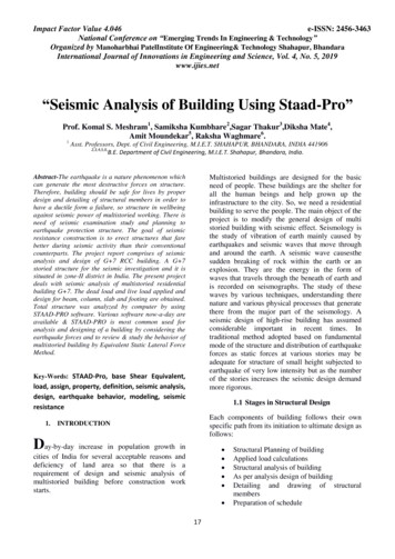
Seismic DesignChapter 6wire-line hammers) shall not be used to collect data used in liquefaction analysis andmitigation design, other than to obtain samples for gradation.The goal of the site characterization for seismic design is to develop the subsurface profileand soil property information needed for seismic analyses. Soil parameters generallyrequired for seismic design include: Dynamic shear modulus at small strains or shear wave velocity; Shear modulus and material damping characteristics as a function of shear strain; Cyclic and post-cyclic shear strength parameters (peak and residual); Consolidation parameters such as the Compression Index or Percent Volumetric Strainresulting from pore pressure dissipation after cyclic loading, and Liquefaction resistance parameters.Table 6-1 provides a summary of site characterization needs and testing considerationsfor geotechnical/seismic design.Chapter 5 covers the requirements for using the results from the field investigation,the field testing, and the laboratory testing program separately or in combination toestablish properties for static design. Many of these requirements are also applicable forseismic design.For routine designs, in-situ field measurements or laboratory testing for parameterssuch as the dynamic shear modulus at small strains, shear modulus and damping ratiocharacteristics versus shear strain, and residual shear strength are generally not obtained.Instead, correlations based on index properties may be used in lieu of in-situ or laboratorymeasurements for routine design to estimate these values. However, if a site specificground motion response analysis is conducted, field measurements of the shear wavevelocity Vs should be obtained.Geotechnical Design Manual M 46-03.12July 2019Page 6-9
Chapter 6Table 6-1GeotechnicalIssuesSeismic DesignSummary of Site Characterization Needs and Testing Considerations for Seismic Design(Adapted From Sabatini, et al., 2002)EngineeringEvaluationsRequired Information for AnalysesField TestingLaboratory TestingSiteResponse sourcecharacterizationand groundmotionattenuation site responsespectra time history subsurface profile (soil, groundwater,depth to rock) shear wave velocity shear modulus for low strains relationship of shear modulus withincreasing shear strain, OCR, and PI equivalent viscous damping ratiowith increasing shear strain, OCR,and PI Poisson’s ratio unit weight relative density seismicity (design earthquakes- source, distance, magnitude,recurrence) SPT CPT seismic cone geophysicaltesting (shearwave velocity) piezometer Atterberg limits grain sizedistribution specific gravity moisturecontent unit weight resonant column cyclic directsimple shear test torsional simpleshear test cyclic action,lateralspreading,slopestability,faulting) liquefactionsusceptibility liquefactiontriggering liquefactioninducedsettlement settlement of drysands lateral spreadingand flow failure slope stabilityand deformations subsurface profile (soil, groundwater,rock) shear strength (peak and residual) unit weights grain size distribution plasticity characteristics relative density penetration resistance shear wave velocity seismicity (PGA, design earthquakes,deaggregation data, ground motiontime histories) site topography SPT CPT seismic cone Beckerpenetration test vane shear test piezometers geophysicaltesting (shearwave velocity) grain sizedistribution Atterberg Limits specific gravity organic content moisturecontent unit weight soil shearstrength tests(static and cyclic) post-cyclicvolumetric strainInput forStructuralDesign soil stiffness forshallow foundations (e.g.,springs) P-Y data for deepfoundations down-drag ondeep foundations residual strength lateral earthpressures lateral spreading/slope movementloading post earthquakesettlement Kinematicsoil-structureinteraction subsurface profile (soil, groundwater,rock) shear strength (peak and residual) coefficient of horizontal subgradereaction seismic horizontal earth pressurecoefficients shear modulus for low strains orshear wave velocity relationship of shear modulus withincreasing shear strain unit weight Poisson’s ratio seismicity (PGA, design earthquake,response spectrum, ground motiontime histories) site topography Interface shear strength CPT SPT seismic cone piezometers geophysicaltesting (shearwave velocity,resistivity,natural gamma) vane shear test pressuremeter grain sizedistribution Atterberg limits specific gravity moisturecontent unit weight resonant column cyclic directsimple shear test triaxial tests(static and cyclic) torsional sheartest direct shearinterface testsPage 6-10Geotechnical Design Manual M 46-03.12July 2019
Seismic DesignChapter 6If correlations are used to obtain seismic soil design properties, and site- or regionspecific relationships are not available, then the following correlations should be used: Table 6-2, which presents correlations for estimating initial shear modulus based onrelative density, penetration resistance or void ratio. Shear modulus reduction and equivalent viscous damping ratio equations by Darendeli(2001) as provided in equations 6-1 through 6-7, applicable to all soils except peatsand gravels. For gravels, shear modulus reduction and viscous damping relationships provided inRollins, et al. (1998). For peats, shear modulus reduction and viscous damping relationships provided inKramer (1996, 2000). Figures 6-1 through 6-3, which present charts for estimating equivalent undrainedresidual shear strength for liquefied soils as a function of SPT blowcounts. Thesefigures primarily apply to sands and silty sands. It is recommended that all thesefigures be checked to estimate residual strength and averaged using a weightingscheme. Table 6-3 presents an example of a weighting scheme as recommendedby Kramer (2007). Designers using these correlations should familiarize themselveswith how the correlations were developed, assumptions used, and any limitationsof the correlations as discussed i
Geotechnical Design Manual M 46-03.12 Page 6-1 July 2019 Chapter 6 Seismic Design 6-1 Seismic Design Responsibility and Policy 6-1.1 Responsibility of the Geotechnical Designer The geotechnical designer is responsible for providing geotechnical/seismic input parameters to the structural engineers for their use in structural design of the