Transcription
HCL Tolerance Stack Analysis Capability1
Agenda1HCL Tolerance Stack Analysis Capability Overview2HCL’s Approach to Tolerance Stack Analysis3Case Studies4GD&T in Drawings2
HCL Tolerance Stack Analysis Capability OverviewOverall TSAExperienceProjectsDeliveredPeople andCertificationsExperience on TSAToolsAreas ofEngagement 10 yearsexperience in TSA Industries Served:Automotive,Aerospace,Medical ctronics,Semiconductorsetc. Successfullycompleted 250 projects in TSAacross domains TSA performed for10 NPD projects 400 Engineershaving experiencein TSA 8 ASME GD&Tcertifiedprofessionals 1D: HCLProprietary TSATools, ClientSpecific Tools 2D / 3D: Top 3TSA tools –CETOL, VIS-VSA,Sigmund Works &CAD Tools NPD Projects –perform TSAbefore production Field FailureInvestigation Perform TSA todetermineproduct costing3
HCL’s Approach to Tolerance Stack Analysis!Take the list offailures from FMEAGather productrequirementsAssemblysequencingArrive at list oftolerance analysisPerform ToleranceStack AnalysisProvide inputs forthe final drawing tobe used forprototype /manufacturing4
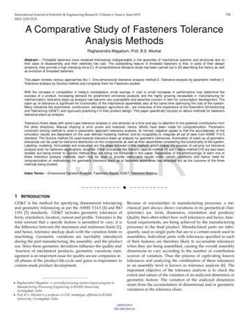
Case Study 1: Reusable StaplerTolerance Loop Purpose Tolerance analysis for identifying critical gapswhich affects the performance of device Inputs for GD&T5
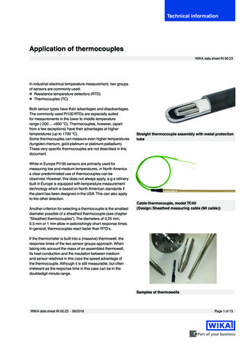
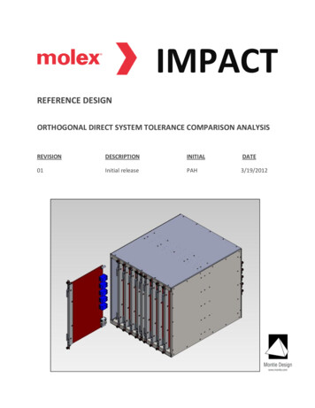
Case Study 2: Torch Nail JigTolerance Loop Purpose Identify drill shift of implant hole1Images removed identify hole size due to drill and sheath variationsResults4540LS Hole :40.47%35TM LS Hole D : 39.89%3025S drill to Sheath Assy :14.43%2015Step Drill : 3.61%10TM to NIJ Assy : 0.96%New HoleDrilled503.841553mmNIJ to NI Assy: 0.60%LS Sheath Assy: 0.04%Hole Onimplant6
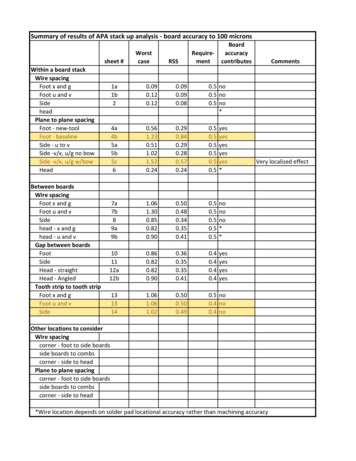
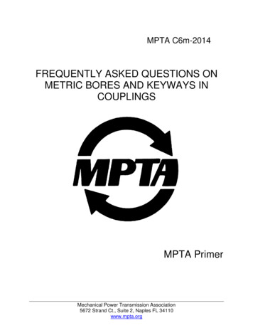
Case Study 3: Cooler Unit 3D AnalysisVSA ModelCAD ModelScope Gap analyzed to identify the failure Max3σ165.0613 169.8693 317.7809 320.5702-3.16833.1503358.5763 362.09144σ164.2600 170.6706 317.3160 321.0351-4.22144.2034357.9905 362.67736σ162.6590 172.2715 316.3872 321.9639-6.32536.3073356.8200 363.8477Output – 4σOutput – 3σ7
GD&T in Drawings Extensively use ASME Y14.5M-1994 in the drawings Widely use the below tolerance types: Form tolerance (Straightness, Flatness) Profile tolerance (Profile of a line, profile of a surface) Orientation (Angularity, Perpendicularity & parallelism) Location (Position, Symmetry) Sample drawings attached: Uses customer specific Design Verification Workbook (DVW) to specify the design intent ofevery dimension and perform tolerance analysis (2D and 3D) to verify the design: Layouts/Overlays Linear tol-stack
GD&T in DrawingsImages removed
THANK YOU!GET IN TOUCH WITH US!
Perform Tolerance Stack Analysis Provide inputs for the final drawing to be used for prototype / manufacturing. Case Study 1: Reusable Stapler 5 Tolerance Loop Purpose Tolerance analysis for identifying critical gaps which affects the performance of device Inputs for GD&