Transcription
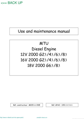
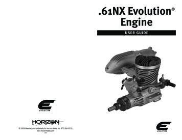
.61NX EvolutionEngineUS E R GU IDE 2008 Manufactured exclusively for Horizon Hobby, Inc. 877-504-0233www.horizonhobby.com12963
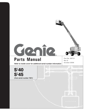
IntroductionCongratulations on your purchase of the newest and oneof the most technically advanced 2-stroke model airplaneengines in the world. Whether you are new to the sport ofmodel aviation or are an experienced flier, you will enjoythe features of the new Evolution Engines NX Engine.The Evolution NX Engine is designed to be the mostpowerful in its class, extremely easy to start and operate,and provide years of enjoyable service. It incorporatesmany unique design features, such as our Set Right needle valve assemblies. Every feature is designed toensure success with your new engine.This user’s guide is intended to provide the basicinformation needed to operate and maintain yourEvolution NX Engine.Every Evolution engine has been baseline adjustedat the factory and is ready to fly . We recommend a shortbreak-in period to become familiar with the engine.Mounting the EngineImportant: While the Evolution engine is extremely easyto operate, if this is your first experience flying a modelairplane, it is highly recommended that you have the helpof an experienced modeler during the first few flights.Your local hobby store or flying club can put you in touchwith an experienced pilot in your area.Glow PlugMuffler NippleMufflerSecurely tighten all engine mounting screws and re-check tightnessbefore each flying session.Most model airplanes include an engine mount. It isextremely important that the engine mount be securelymounted to the airplane’s firewall and that the engineis securely mounted to the engine mount. Follow theinstructions included with the airplane for mounting theengine.Fuel NippleHigh-Speed NeedleImportant: Before each flying session, check that allengine mounting screws are securely tightened.Installing the MufflerUsing the included muffler mounting screws and lockwashers, attach the muffler with the included hexwrench. Be sure the lock washers are placed over thescrews and that one gasket is placed between the mufflerand the engine. A second gasket is included as a spare.Securely tighten both screws with moderate torque.Important: After five runs, retighten the mufflermounting screws. Heat and vibration from these firstfew runs can cause the gasket to compress. Once themuffler screws are retightened, they will remain tight andleak-free until the muffler is removed. Also, tighten themuffler thru-bolt at this time as well—loosen the locknut on the back of the muffler, tighten the thru-bolt viathe screwhead at the front of the muffler then retightenthe lock nut at the rear.Throttle LinkageGlow PlugMufflerLow-Speed NeedleThrottle Arm2The muffler mounting accessory package includes mounting screws(2), lock washers (2), muffler gaskets (2) and an L- wrench.Attach the linkage to the throttle arm.A clevis is recommended for attaching the throttlelinkage to the throttle. Attach the throttle linkage to thehole in the throttle arm (see photo above).Turn on the radio. With the throttle stick at 1/2 throttle,install the arm on the servo so that the arm is 90 to thethrottle pushrod.3
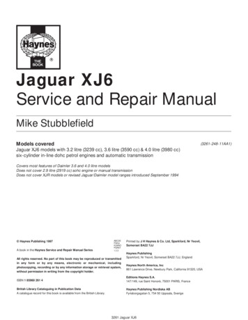
Select a servo arm that has a hole located 11mm or7/16" out from center and attach the other end of thethrottle linkage. (see photos below)Attaching the Propeller and SpinnerAttaching the Fuel LinesStarting the Evolution EngineFuelWe recommend using high quality Cool Power Omega,Hangar 9 AeroBlend or Power Master fuels containing10 to 15% Nitro. The Evolution engine has been testrun using these fuels. If another brand of fuel is used, itmay be necessary to slightly adjust the needle valves tocompensate for the differences in fuel.Glow PlugLinkage 11mm outThe Evolution engine comes with a specially designed“Super Plug” that prevents idle and transition flameouts.The plug’s unique shape directs incoming fuel/air mixtureaway from the plug element. When replacing the plug,be sure to replace it with another Evolution 2- or 4-cycleSuper Plug (EVO6P1).Fuel LineVent LineStarting the EngineSecurely tighten the prop nut using a wrench.15% fuel.Step 2. Reattach the fuel lines, making sure the ventand clunk line are attached to the fuel nippleand the muffler pressure nipple.Vent LineCaution: Do not attach the glow driver yet.Step 3. With the throttle fully open, place your thumbover the carburetor and flip the prop clockwisethrough 6 complete revolutions, thus priming theengine.Step 4. Close the throttle to the idle position and have ahelper hold your airplane.1/2 throttleFuel Line1mmAt low throttle, mid-trim, the throttle barrel should be 1mm open.With low throttle and mid-trim (idle position), the throttlebarrel should be open 1mm, giving a low rpm idle (seephoto above). Adjust the length of the pushrod until thethrottle barrel is exactly 1mm open. Check to be surethe servo is moving in the correct direction. Full throttleshould open the throttle barrel fully, while low throttleand low-trim should completely close the throttle barrel.Reverse the servo throw if necessary. Note: It may be necessary to slightly adjustthe length of the throttle pushrod to achievethe correct mid-trim, low-stick idle position.4Using medium silicone fuel tubing, attach the fuel tank’sclunk line to the fuel nipple. This line will supply fuel tothe engine. Attach the vent line to the muffler pressurenipple. This line pressurizes the fuel tank with the mufflerpressure, creating consistent fuel flow, regardless of theairplane’s attitude.Recommended propellers:Break in11 x 7Step 1. Fill the tank with the above-mentioned 10 orRemove the prop nut and prop washer from the engine.Install the spinner back plate. Install the propeller, theprop washer and then the prop nut in that order (seephoto). Securely tighten the prop nut using a wrench.Install the spinner cone.Sport11 x 7, 11 x 812 x 6, 12 x 713 x 6, 13 x 7The Hangar 9 START KIT (HANSTART) includes everything needed,except fuel and starter, to get the Evolution engine running.5
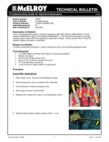
Step 5. Attach the glow driver.Step 6. Turn the engine over using an electric starter.The engine should fire within seconds of applyingthe starter.Step 7. Allow the engine to idle for 30 seconds. Adjust thethrottle trim if necessary to achieve a constantslow idle.Step 8. With the glow driver still attached and a helpersecurely holding the airplane, advance thethrottle smoothly to full throttle. The engine willtransition to full rpm.Step 9. Reduce the throttle to idle and remove theglow driver.Needle LimitersThe high- and low-speed needles have limiters thatprevent over-adjustment. If your engine starts from theabove procedure, but won’t reliably continue to run withthe glow driver removed, follow the steps below.airplane. Carefully pinch and release the fuel lineto temporarily restrict the fuel flow. Caution: Do not reach over the propeller whilethe engine is running. Correct: If the high-speed needle adjustmentis correct, the engine will increase rpm slightly(about 300 rpm) and then die.T oo Rich: If the engine increases a lot (1,000rpm or greater), the high-speed needle is too richand must be leaned or turned clockwise.T oo Lean: If the engine doesn’t increase rpm andsimply dies, the high-speed needle is lean andmust be richened or turned counterclockwise.Step 2. Low-Speed Needle Adjustment The low-speed or idle needle valve, includedwith the SetRight assembly, is preadjusted atthe factory for best performance at close to sealevel conditions. It may be necessary to fine-tunethe low-speed adjustment using the followingprocedure:Step 1. High-Speed Needle Adjustment With the engine running, advance the throttleto full throttle while a helper securely holds your 1. Start the engine and let it warm up, priorto attempting any adjustments. Make surethat the high-speed adjustment process iscomplete before attempting to adjust thelow-speed needle valve.2 . Close the throttle slowly. You will adjust thelow-speed needle setting by rotating theSetRight adjustment bar clockwise to leanthe engine and counterclockwise to richen theengine. Caution: Do not attempt to adjust the low-speedneedle valve while the engine is running.High-Speed Needle AdjustmentLow-Speed Needle AdjustmentNote that the needle adjustment range is limited, preventing adjustment beyond the practical range.63 . The fuel mixture should be adjusted asfollows: The fuel mixture is too rich if, whenopening the throttle rapidly, the engine emitssmoke and "stutters" or "stumbles." Correctthis by rotating the SetRight adjustment barclockwise in small increments. Continue thisprocess until the engine transitions smoothlyfrom low rpm idle to high rpm without hesitationupon opening the throttle rapidly.Step 2. Low-Speed Needle Adjustment, cont. 4. The fuel mixture may be too lean if the enginestops at the lowest idle position or it stops whenthe throttle is rapidly opened from the idle position.Correct this by rotating the SetRight adjustmentbar counterclockwise in small increments until theengine transitions smoothly without hesitation uponopening the throttle rapidly from idle.SetRight Needle ValvesThe design of the SetRight needle valve system is suchthat, during normal operating conditions, the typicaluser will find that the range of adjustment allowed bythe system is more than adequate for most situations.As a matter of fact, we intended this to be used as atool to identify operating problems. If you find that therange of adjustment allowed by the SetRight needle isinadequate after your initial period of running, then aproblem in your engine system has occurred. This mightbe a bad glow plug, dirty or old fuel, an air leak in thefuel system somewhere or any number of other reasons.Do not make any permanent adjustment range changesto the SetRight needle system if it was once workingcorrectly for you and now does not. Investigate otherproblems first.However, occasionally due to atmospheric, altitudinalor fuel conditions, you may find that the range ofadjustment built into the SetRight needle valve systemis inadequate for your needs. These conditions are rareand easy to fix.High-Speed SetRight Needle Valve Correction Should the high-speed SetRight needle valveneed to be adjusted outside of the factoryestablished parameters, simply pull out thedetent spring on the high-speed needleassembly and move the needle valve in thedesired direction so the SetRight pin passesthe spring detent. You now have re-establisheda new range for your purposes. You can alsoloosen the setscrew on the collar holding thedetent spring and rotate this in thedesired direction.Low-Speed SetRight Needle Valve Correction Should the low-speed SetRight needle valveneed to be adjusted outside the factoryestablished parameters, follow these steps: A. Loosen the setscrew found on the ring ofthe SetRight assembly to which theadjustment bar is attached. B. Rotate the needle valve itself (smallslot-headed screw inside the blue ring ofthe SetRight assembly) clockwise to leanthe mixture or counterclockwise to richenthe mixture as desired. C. Retighten the setscrew on the ring ofthe SetRight assembly and you havere-established a new range of motion.Why would fuel go “bad”?The largest portion of the fuel is methanol (alcohol).Methanol is hygroscopic; it attracts moisture. This cancause your fuel to be contaminated with water, which willcause poor engine performance. Additionally, the UV raysin sunlight will eventually break down the nitromethane ifthe fuel jug is stored in sunlight for long periods of time.How can you tell when your fuel has gone “bad”?The first indication will generally be the inability to startthe engine at previously run needle-valve settings.Another clue might be that the engine has very poor idle,runs but bogs down tremendously during run up and/orwill not attain the same rpms that you are used to.How do I keep my fuel fresh?If you have the opportunity, look for someone at a flyingfield on a sunny day who has a jug of fuel that is only1/4 full. What you may notice is that there are dropletsattached to the top and sides of the container. This isthe moisture in the air that is condensing inside the jugbecause of the greenhouse effect of the semi-translucentplastic jug. This will also occur within a metal fuel can asthe sun warms the contents.You can combat the effects of the moisture in the air bysqueezing all the extra air from your fuel container atthe end of the day or transferring your fuel into smallercontainers as the level of the fuel is reduced in your7
gallon jug. Many pilots will invest in 1/2 gallon or quartsize containers and only bring that amount of fuel to thefield on any given day. This allows their main supply offuel to stay at home in a controlled storage environment,virtually ensuring problem-free fuel.How to Tell If Your Glow Plug Is BadThe glow plugs on the market today are designedto provide good service to the user and may last a longtime or a short time, all dependent upon the way youchoose to operate your engine.Physical indications that you might need tochange the glow plug are:1. Twisted or mangled glow plug element (usuallycaused by too high a compression ratio).2. Small “bumps” are attached to the glow plugelement. This will generally be most noticeableduring the break-in process. These are actuallytiny pieces of aluminum that have attached to theelement and will severely hinder the operation ofthe glow plug.3. The glow plug element is no longer shiny but is dull,almost a white powder color. (This just comes withage and is a by-product of the catalytic reaction).The shinier the wire, the better the catalytic reactioncan be.NX Evolution Engines SpecificationsOperating indications that you need to changeyour glow plug are:1. The glow element will not light with a charged glowigniter. This indicates that there is a physical shortor breakage in the element wire itself.2. Glow plug lights but the engine will not continuerunning once the battery is disconnected. (This isusually an indication of the microscopic particleswe discussed earlier.)3. Glow plug lights, engine runs but there is aperceptible loss of rpm at full throttle when thebattery is disconnected. This is a typical indicationthat the white powder residue is building to thepoint that the catalytic reaction of the glow plug isno longer anywhere close to being X6FHGB ACDimensions (mm)EVOE0611A43B52Troubleshooting GuideEngine Won’t FireEngine Quits Repeatedly Needles need adjusting- See adjustment procedure Bad or old fuel- Replace with fresh fuel Worn out glow plug- Replace with new EVOGP1 glow plugEngine Runs Inconsistently Hole in fuel line- Replace fuel line Bad or old fuel- Replace with fresh fuelE heightF lengthG crankshaft thread sizeH muffler bolt spacingD Glow starter not charged- Charge glow starter Glow plug burnt out- Replace glow plug No fuel is getting to the carburetor- Check tank, fuel lines reversed The starter is reversed- Reverse the polarity on the starter cables8Crank K(ISO)5/16 x 24C25D55E84F102G5/16 x 24H42MaintenanceAfter each flying session:1. Fully drain the fuel from the tank.2. Start the engine and run it until the fuel iscompletely run out of the engine.3. Try starting the engine three more times or untilit will no longer fire. This gets all the fuel out ofthe engine.If the engine will not be used within 10 days, severaldrops (about 10) of after-run oil (EVOX10000 EvolutionEngine's Blue Block Rust Inhibitor) should be applied intothe carburetor and the engine should be turned over fora few seconds with the starter. This will prevent rustand corrosion.If you need additional help or have any questions, please callHorizon’s Service Center. Horizon has trained technicians whoare qualified to answer your engine questions.Evolution/Horizon Service Center4105 Fieldstone RoadChampaign, IL 61822877-504-02339
36 (17 & 35)16Cross-Reference of Evolution .61 NX Part NumbersNo. Description171335, 3616333433191516191413111910 seRear Cover with GasketPiston & Liner Set (ABC)Connecting Rod (Dual Bushing)Wrist Pin w/Clips (Teflon)Crankshaft (5/16 x 24)Cylinder HeadCylinder Head ShimProp Driver & ColletCarburetor Retainer (Drawbar)Prop WasherProp Nut (5/16 x 24)Gasket Set, EngineBall Bearing, Front (Rubber Seal)Ball Bearing, Rear (Open Race)Screw Set, EngineCarburetor, CompleteMufflerMuffler Mounting Screwset w/Gasket342928EVO0618701 CrankcaseEVO06110123 Spraybar Bracket (Remote)2 Rear Cover w/GasketEVO06110224 High-Speed Needle Valve RatchetEVO1008333 Piston & Liner Set (ABC)EVO06120325 Collar w/SetscrewEVO100834A4 Connecting Rod Set (Dual Bushing)EVO8020426 Spraybar, RemoteEVO1008305 Wrist Pin w/Clips (Teflon)EVO06121327 Throttle BarrelEVO0618136 Crankshaft (5/16 x 24)EVO06121028 Spring, Throttle BarrelEVO100814A7 Cylinder HeadEVO061103B29 Idle NeedleEVO100844A8 Cylinder Head ShimEVO06111230 Throttle ArmEVO100864A9 Prop Driver & ColletEVO061238X31 Idle Needle Limit CollarEVO100850A10 Carburetor Retainer (Drawbar)EVO06112932 Idle Stop Screw w/NutEVO061837F11 Prop WasherEVO06122833 Carburetor Gasket/O-Ring SetEVO061E61BEVO061E61C12 Prop Nut (5/16 x 24)EVO06122834 Small Parts Set, Carburetor13 Gasket Set, EngineEVO06141635 Needle Valve AssemblyEVO06187414 Ball Bearing, Front (Rubber seal)EVO06110936 Carburetor w/Remote NV AssemblyEVO06180315 Ball Bearing, Rear (Open Race)EVO06111016 Screw Set, EngineEVO06190117 Carburetor CompleteEVO06180118 MufflerEVO06160119 Muffl er Mounting Screw Set w/GasketEVO061E61A20 Carburetor Body (w/Spraybar)EVO06186321 Fuel Nipple & GasketEVO06181922 High-Speed Needle 536Carburetor Body w/SpraybarFuel Nipple & GasketHigh-Speed Needle ValveSpraybar Bracket (Remote)High-Speed Needle Valve RatchetCollar w/SetscrewSpraybar (Remote)Throttle BarrelThrottle Barrel SpringIdle NeedleThrottle ArmIdle Needle Limit CollarIdle Needle Stop Screw w/NutCarburetor Gasket, O-Ring SetSmall Parts Set, CarburetorNeedle Valve AssemblyCarburetor w/Remote NV Assembly11
Warranty PeriodExclusive Warranty- Horizon Hobby, Inc., (Horizon)warranties that the Products purchased (the“Product”) will be free from defects in materials andworkmanship for a period of 2 years from the date ofpurchase by the Purchaser.Limited Warranty(a) This warranty is limited to the original Purchaser(“Purchaser”) and is not transferable. REPAIR ORREPLACEMENT AS PROVIDED UNDER THIS WARRANTYIS THE EXCLUSIVE REMEDY OF THE PURCHASER. Thiswarranty covers only those Products purchased froman authorized Horizon dealer. Third party transactionsare not covered by this warranty. Proof of purchase isrequired for warranty claims. Further, Horizon reservesthe right to change or modify this warranty withoutnotice and disclaims all other warranties, express orimplied.(b) Limitations- HORIZON MAKES NO WARRANTY ORREPRESENTATION, EXPRESS OR IMPLIED, ABOUTNON-INFRINGEMENT, MERCHANTABILITY OR FITNESSFOR A PARTICULAR PURPOSE OF THE PRODUCT. THEPURCHASER ACKNOWLEDGES THAT THEY ALONE HAVEDETERMINED THAT THE PRODUCT WILL SUITABLYMEET THE REQUIREMENTS OF THE PURCHASER’SINTENDED USE.(c) Purchaser Remedy- Horizon’s sole obligationhereunder shall be that Horizon will, at its option,(i) repair or (ii) replace, any Product determinedby Horizon to be defective. In the event of a defect,these are the Purchaser’s exclusive remedies. Horizonreserves the right to inspect any and all equipmentinvolved in a warranty claim. Repair or replacementdecisions are at the sole discretion of Horizon.This warranty does not cover cosmetic damage ordamage due to acts of God, accident, misuse, abuse,negligence, commercial use, or modification of or toany part of the Product. This warranty does not coverdamage due to improper installation, operation,maintenance, or attempted repair by anyone otherthan Horizon. Return of any goods by Purchaser mustbe approved in writing by Horizon before shipment.Damage LimitsHORIZON SHALL NOT BE LIABLE FOR SPECIAL,INDIRECT OR CONSEQUENTIAL DAMAGES, LOSS OFPROFITS OR PRODUCTION OR COMMERCIAL LOSS INANY WAY CONNECTED WITH THE PRODUCT, WHETHER12SUCH CLAIM IS BASED IN CONTRACT, WARRANTY,NEGLIGENCE, OR STRICT LIABILITY. Further, in no eventshall the liability of Horizon exceed the individualprice of the Product on which liability is asserted. AsHorizon has no control over use, setup, final assembly,modification or misuse, no liability shall be assumednor accepted for any resulting damage or injury. Bythe act of use, setup or assembly, the user accepts allresulting liability.If you as the Purchaser or user are not preparedto accept the liability associated with the use ofthis Product, you are advised to return this Productimmediately in new and unused condition to the placeof purchase.LAW: These Terms are governed by Illinois law (withoutregard to conflict of law principals).Safety PrecautionsThis is a sophisticated hobby Product and not a toy.It must be operated with caution and common senseand requires some basic mechanical ability. Failure tooperate this Product in a safe and responsible mannercould result in injury or damage to the Product orother property. This Product is not intended for use bychildren without direct adult supervision. The Productmanual contains instructions for safety, operationand maintenance. It is essential to read and follow allthe instructions and warnings in the manual, prior toassembly, setup or use, in order to operate correctlyand avoid damage or injury.Questions, Assistance, and RepairsYour local hobby store and/or place of purchase cannotprovide warranty support or repair. Once assembly,setup or use of the Product has been started, youmust contact Horizon directly. This will enable Horizonto better answer your questions and service you inthe event that you may need any assistance. Forquestions or assistance, please direct your emailto productsupport@horizonhobby.com, or call877.504.0233 toll free to speak to a service technician.Inspection or RepairsIf this Product needs to be inspected or repaired,please call for a Return Merchandise Authorization(RMA). Pack the Product securely using a shippingcarton. Please note that original boxes may beincluded, but are not designed to withstand the rigorsof shipping without additional protection. Ship via acarrier that provides tracking and insurance for lostor damaged parcels, as Horizon is not responsible formerchandise until it arrives and is accepted at ourfacility. A Service Repair Request is available at www.horizonhobby.com on the “Support” tab. If you do nothave internet access, please include a letter withyour complete name, street address, email addressand phone number where you can be reached duringbusiness days, your RMA number, a list of the includeditems, method of payment for any non-warrantyexpenses and a brief summary of the problem. Youroriginal sales receipt must also be included forwarranty consideration. Be sure your name, address,and RMA number are clearly written on the outside ofthe shipping carton.Warranty Inspection and RepairsTO RECEIVE WARRANTY SERVICE, YOU MUST INCLUDEYOUR ORIGINAL SALES RECEIPT verifying the proofof-purchase date. Provided warranty conditions havebeen met, your Product will be repaired or replaced freeof charge. Repair or replacement decisions are at thesole discretion of Horizon Hobby.Non-Warranty RepairsSHOULD YOUR REPAIR NOT BE COVERED BYWARRANTY, THE REPAIR WILL BE COMPLETED ANDPAYMENT WILL BE REQUIRED WITHOUT NOTIFICATIONOR ESTIMATE OF THE EXPENSE UNLESS THE EXPENSEEXCEEDS 50% OF THE RETAIL PURCHASE COST. Bysubmitting the item for repair you are agreeing topayment of the repair without notification. Repairestimates are available upon request. You mustinclude this request with your repair. Non-warrantyrepair estimates will be billed a minimum of ½ hourof labor. In addition you will be billed for return freight.Please advise us of your preferred method of payment.Horizon accepts money orders and cashiers checks,as well as Visa, MasterCard, American Express, andDiscover cards. If you choose to pay by credit card,please include your credit card number and expirationdate. Any repair left unpaid or unclaimed after 90 dayswill be considered abandoned and will be disposed ofaccordingly. PLEASE NOTE: NON-WARRANTY REPAIRIS ONLY AVAILABLE ON ELECTRONICS AND MODELENGINES.United States:Electronics and engines requiring inspection or repairshould be shipped to the following address:Horizon Service Center4105 Fieldstone RoadChampaign, Illinois 61822All other Products requiring warranty inspection orrepair should be shipped to the following address:Horizon Product Support4105 Fieldstone RoadChampaign, Illinois 61822PLEASE CALL 877-504-0233WITH ANY QUESTIONS OR CONCERNSREGARDING THIS PRODUCT OR WARRANTY.European Union:Electronics and engines requiring inspection orrepair should be shipped to the following address:Horizon Hobby UKUnits 1-4 Ployters RdStaple TyeSouthern WayHarlowEssex CM18 7NSUnited KingdomPLEASE CALL 44 (0) 1279 641 097OR sales@horizonhobby.co.ukWITH ANY QUESTIONS OR CONCERNSREGARDING THIS PRODUCT OR WARRANTY.13
The Evolution engine comes with a specially designed "Super Plug" that prevents idle and transition flameouts. The plug's unique shape directs incoming fuel/air mixture away from the plug element. When replacing the plug, be sure to replace it with another Evolution 2- or 4-cycle Super Plug (EVO6P1). Starting the Engine Step 1.