Transcription
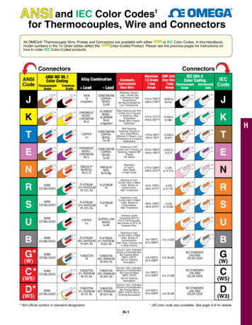
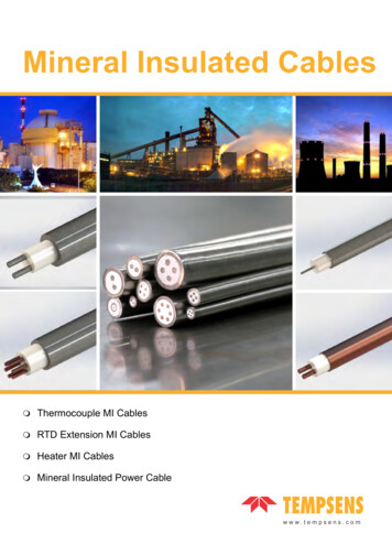
Technical informationApplication of thermocouplesWIKA data sheet IN 00.23In industrial electrical temperature measurement, two groupsof sensors are commonly used: Resistance temperature detectors (RTD) Thermocouples (TC)Both sensor types have their advantages and disadvantages.The commonly used Pt100 RTDs are especially suitedfor measurements in the lower to middle temperaturerange (-200 . 600 C). Thermocouples, however, (apartfrom a few exceptions) have their advantages at highertemperatures (up to 1700 C).Some thermocouples can measure even higher temperatures(tungsten-rhenium, gold-platinum or platinum-palladium).These very specific thermocouples are not described in thisdocument.While in Europe Pt100 sensors are primarily used formeasuring low and medium temperatures, in North Americaa clear predominated use of thermocouples can beobserved. However, this does not always apply, e.g a refinerybuilt in Europe is equipped with temperature measurementtechnology which is based on North American standards ifthe plant has been designed in the USA. This can also applyto the other direction.Another criterion for selecting a thermocouple is the smallestdiameter possible of a sheathed thermocouple (see chapter“Sheathed thermocouples”). The diameters of 0.25 mm,0.5 mm or 1 mm allow in astonishingly short response times.In general, thermocouples react faster than RTD's.Straight thermocouple assembly with metal protectiontubeCable thermocouple, model TC40(Design: Sheathed measuring cable (MI cable))If the thermometer is built into a (massive) thermowell, theresponse times of the two sensor groups approach. Whentaking into account the mass of an assembled thermowell,its heat conduction and the insulation between mediumand sensor relativise in this case the speed advantage ofthe thermocouple. Although it is still measurable, but oftenirrelevant as the response time in this case can be in thedoubledigit minute range.Samples of thermowellsWIKA data sheet IN 00.23 09/2016Page 1 of 13
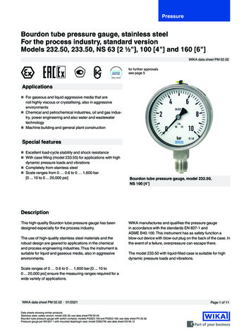
BasicsEvery metal has a material-specific electronegativity.(Electronegativity tendency of atoms rather to accept orrelease electrons)A thermocouple consists of two conductors of dissimilarmetals connected together at one end, whereby theconnection node is the measuring point.Thermocouple/measuring pointCeramic insulationThermocouple conductorsFollowing standards define thermocouplesIEC 60584-1: Thermocouples: basic and tolerance values ofthe thermoelectric voltagesIEC 60584-3: Thermocouples: Thermocouple cables andcompensating cablesWhen the measuring point is heated, the voltage on thewire ends (cold junction) is measured; it represents thetemperature of the measuring point.(Thermoelectric effect Seebeck effect)Metal AT1MeasuringpointColdjunctionMetal BTo achieve the highest possible thermoelectric voltages,special material pairings whose individual electronegativitiesare as far apart as possible are used to form thermocouples.These material pairings have certain limitations - forexample due to the maximum operating temperature of thethermocouple.ASTM E230:Standard specification and temperature-electromotive force(EMF) tables for standardised thermocouples.T2This voltage (EMF electromotive force) is produced dueto different electron density of the two (dissimilar) metalconductors of the wires used - in combination with thetemperature difference between measuring point and coldjunction.Simply, a thermocouple measures not the absolutetemperature, but the differential temperature between the T1: Measuring point (hot junction)and T2: Cold point (cold junction)Since the voltage is often measured at ambient temperature,the displayed voltage value would be too low by the value ofthe voltage of the ambient temperature. To obtain the valuefor the absolute measuring point temperature, the so-called“cold junction compensation” is used.In the past (in calibration laboratories still today), it wasachieved by means of immersing the joint of the cold end ofthe thermocouple and the wires of the voltage meter into anice bath.In current instruments with thermocouple input (transmitters,portable measuring instruments or panel mounted devices,etc.), an electronic cold junction compensation is included inthe circuitry of the instrument.Page 2 of 13WIKA data sheet IN 00.23 09/2016
Thermoelectric voltagesReference temperature: 0 CTemperaturein C-200ThermocoupleType KType JType NType 00Type B-3.923-120-20Type R-4.419-1400Type S-4.865-160-40-5.603-5.261-180-60Type 86810.09910.679Continued on next pageWIKA data sheet IN 00.23 09/2016Page 3 of 13
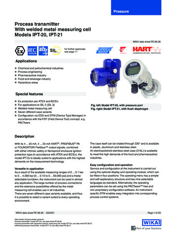
Temperaturein C1600ThermocoupleType KType JType NType E16501700Type TType S16.777Type R18.849Type B11.26311.85012.430Legend:Black: IEC 60584-1 and ASTM E230Blue: IEC 60584-1 onlyRed: ASTM E230 onlyThermoelectric voltage curvesVoltage IEC 60584-1Voltage ASTM E230The charts illustrate the curves corresponding to the relevanttemperature ranges of IEC 60584-1 / ASTM E230. Outsidethese temperature ranges, the permissible tolerance value isnot standardised.Page 4 of 13WIKA data sheet IN 00.23 09/2016
Operating limits and accuracies of thermocouples(IEC 60584, ASTM E230)The following table contains permissible tolerance values of IEC 60584-1 incl. the tolerance values of ASTM E230 standardwhich is common in North America:Tolerance values of the thermocouples per IEC 60584-1 / ASTM E230 (Reference temperature 0 C)TypeKNThermocoupleNiCr-NiAl (NiCr-Ni)NiCrSi-NiSiTolerance valueIEC 60584-1Class1Temperature range2Fe-CuNiNiCr-CuNiCu-CuNi-40 . 750 C 1.5 C or 0.0040 t 0 . 1260 C2-40 . 750 C 2.5 C or 0.0075 t 0 . 1260 C0 . 760 CIEC 60584-11-40 . 800 C 1.5 C or 0.0040 t 2-40 . 900 C 2.5 C or 0.0075 t IEC 60584-1IEC 60584-10 . 760 C 1.1 C or 0.4 % 2.2 C or 0.75 %Special0 . 870 C 1.0 C or 0.4 %Standard0 . 870 C 1.7 C or 0.5 %1-40 . 350 C 0.5 C or 0.0040 t 2-40 . 350 C 1.0 C or 0.0075 t -200 .Special 40 C0 . 370 C-200 0 C 1.0 C or 0.015 t 0.5 C or 0.4 % 1.0 C or 1.5 %Standard0 . 370 C 1.0 C or 0.75 %10 . 1600 C 1.0 C or [1 0.003 (t - 1100)] C20 . 1600 C 1.5 C or 0.0025 t ASTM E230Special0 . 1480 C 0.6 C or 0.1 %IEC 60584-12 600 . 1700 C 0.0025 t 3 600 . 1700 C 4.0 C or 0.005 t Special--Standard 870 . 1700 C 0.5 %StandardPt30%Rh-Pt6%Rh 2.2 C or 0.75 %SpecialStandardB 1.1 C or 0.4 %ASTM E2303Pt13%Rh-PtPt10%Rh-Pt 2.5 C or 0.0075 t 1ASTM E230RS-40 . 1200 CIEC 60584-1ASTM E230T 1.5 C or 0.0040 t 1) 2)SpecialStandardE-40 . 1000 CASTM E230StandardJTolerance valueASTM E2300 . 1480 C 1.5 C or 0.25 %1) ItI is the value of the temperature in C without consideration of the sign2) The greater value appliesThere are different notations of type K thermocouples in Europe and North America:Europe:NiCr-NiAl or NiCr-NiNorth America: Ni-Cr / Ni-AlThere is no physical difference, it is just the naming caused by historical reasons.Types R, S and BNot available as MI-cable version in class 1 per IEC 60584 or “Special” per ASTM E230WIKA data sheet IN 00.23 09/2016Page 5 of 13
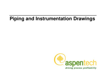
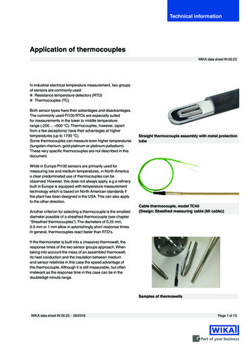
For the tolerance value of thermocouples, a cold junction temperature of 0 C has beentaken as the basis. When using a compensating cable or thermocouple cable, an additionalmeasuring deviation must be considered.1098Tolerance value in C76Legend:Type K Class 2Type K Class 15432100200400600800100012001400Temperature in CExample:Tolerance value of the accuracy classes 1 and 2 of thermocouple type KPage 6 of 13WIKA data sheet IN 00.23 09/2016
Information on the application of thermocouples Base-metal thermocouplesType K leg- legNiCr-NiAlNickel-Chromium-Nickel-Aluminum (ferromagnetic)NiCr-NiAl thermocouples are suitable for use in oxidising orinert gas atmospheres up to 1200 C (ASTM E230: 1260 C)with the largest wire size.Protect thermocouples from sulphurous atmospheres. Sincethey are less susceptible to oxidation than thermocouplesmade of other materials, they are mostly used forapplications at temperatures above 550 C up to themaximum working pressure of the thermocouple.Type J legFe-CuNi-Copper-Nickel leg- onNiCrSi-NiSi thermocouples are suitable for use in oxidisingatmospheres, in inert gas atmospheres or dry reductionatmospheres up to 1200 C (ASTM E230: 1260 C).They must be protected from sulphurous atmospheres. Theyare very accurate at high temperatures. The source voltage(EMF) and the temperature range are almost the same aswith type K. They are used in applications where a longerservice life and greater stability are required.Type E leg- legNiCr-CuNiNickel-Chromium-Copper-NickelNiCr-CuNi thermocouples are suitable for use inoxidising or inert gas atmospheres up to 900 C(ASTM E230: 870 C) with the largest wire size. Type Ethermocouples, of all the commonly used thermocouples,develop the highest source voltage (EMF) per C.WIKA data sheet IN 00.23 09/2016- legCu-CuNiCopper-Copper-Nickel Precious-metal thermocouples- legIron (ferromagnetic) legCu-CuNi thermocouples are suitable for temperaturesbelow 0 C with an upper temperature limit of 350 C(ASTM E230: 370 C) and can be used in oxidising, reducingor inert gas atmospheres. They do not corrode in moistatmospheres.Type SFe-CuNi thermocouples are suitable for use in vacuum,in oxidising and reducing atmospheres or inert gasatmospheres. They are used for temperature measurementsup to 750 C (ASTM E230: 760 C) with the largest wire size.Type NType T leg- legPt10%Rh-PtPlatinum-10%Rhodium-PlatinumType S thermocouples are suitable for continuous use inoxidizing or inert atmospheres at temperatures up to 1600 C.Beware of embrittlement due to contamination.Type R leg- legPt13%Rh-PtPlatinum-13%Rhodium-PlatinumType R thermocouples are suitable for continuous use inoxidising or inert gas atmospheres at temperatures up to1600 C. Beware of embrittlement due to contamination.Type B leg- odiumType B thermocouples are suitable for continuous use inoxidising or inert gas atmospheres and for short-term usein vacuum environments for temperatures up to 1700 C.Beware of embrittlement due to contamination.Type R, S and B thermocouples are commonly installedin a pure ceramic closed-ended protection tube. If a metalthermowell or protection tube is used, an inner closed-endedprotection tube is required. Precious metal thermocouplesare susceptible to contamination. It is strongly recommendedto surround these thermocouples with ceramic material.Page 7 of 13
Recommended upper temperature limit(Continuous operation) Sheathed thermocouples (see also table “Thermoelectric voltages per IEC 60584-1”)ThermocoupletypeRecommended upper temperature limit in CK700With sheath diameter in 50350Sheath material: Inconel 2.4816 (Inconel 600)Specifications under consideration of optimum laboratory conditions (relating to air without harmful gases).Other materials are available resulting in different temperature limits. Straight thermocouple assembly (see also table “Thermoelectric voltages per IEC 60584-1”)ThermocoupletypeRecommended upper temperature limit in CWith wire diameter in 00T800--1500---Specifications under consideration of optimum laboratory conditions (relating to air without harmful gases). Protected thermocouples (see also table “Suggested upper temperature limits for protected thermocouples”per ASTM E230)ThermocoupletypeTJEK and NR and SBUpper temperature limit for various wire sizes (Awg) in CNo. 30 gauge0.25 mm[0.010 inch]150320370760No. 28 gauge0.33 mm[0.013 inch]200370430870No. 24 gauge0.51 mm[0.020 inch]2003704308701480No. 20 gauge0.81 mm[0.032 inch]260480540980No. 14 gauge1.63 mm[0.064 inch]No. 8 gauge3.25 mm[0.128 inch]590760370650109087012601700Note:The specified maximum operating temperatures apply to thethermocouple under optimal environmental conditions. Themaximum working temperature of the thermowells is oftenwell under the temperature of the thermocouple!Page 8 of 13WIKA data sheet IN 00.23 09/2016
Sheathed thermocouples (see also table “Suggested upper temperature limits for sheathed thermocouples”per
(IEC 60584, ASTM E230) The following table contains permissible tolerance values of IEC 60584-1 incl. the tolerance values of ASTM E230 standard which is common in North America: Tolerance values of the thermocouples per IEC 60584-1 / ASTM E230 (Reference temperature 0 C) Type Thermocouple Tolerance value Class Temperature range Tolerance value K N