Transcription
MPTA C6m-2014FREQUENTLY ASKED QUESTIONS ONMETRIC BORES AND KEYWAYS INCOUPLINGSMPTA PrimerMechanical Power Transmission Association5672 Strand Ct., Suite 2, Naples FL 34110www.mpta.org
MPTA-C6m-2009FAQ ON METRIC BORES AND KEYWAYS IN COUPLINGSContributorsAltra Industrial Motion – TB Wood’sChambersburg, PAwww.tbwoods.comGreenville, SCwww.baldor.comEmerson Power TransmissionMaysville, KYwww.emerson-ept.comFrontline Industries, Inc.Irvington, NJLovejoy, Inc.Downers Grove, ILwww.lovejoy-inc.comMagnaloy Coupling CompanyDenver, COwww.gates.comMartin Sprocket & Gear, Inc.Arlington, TXwww.martinsprocket.comMaurey Manufacturing Corp.Holly Springs, MSwww.maurey.comRexnord Industries, LLCNew Berlin, WIwww.rexnord.comBaldor Dodge Maskawww.frontlineindustries.comDisclaimer StatementThis publication is presented for the purpose of providing reference information only.You should not rely solely on the information contained herein. Mechanical PowerTransmission Association (MPTA) recommends that you consult with appropriateengineers and / or other professionals for specific needs. Again, this publication is forreference information only and in no event will MPTA be liable for direct, indirect,incidental or consequential damages arising from the use of this information.AbstractThis primer is intended for individuals who need additional information on thefundamentals of the metric bore and keyway system. It presents answers to commonquestions related to a coupling’s bore and keyway.Copyright Position StatementMPTA publications are not copyrighted to encourage their use throughout industry. It isrequested that the MPTA be given recognition when any of this material is copied forany use.Mechanical Power Transmission Association5672 Strand Ct., Suite 2, Naples, FL 34110www.mpta.orgPage 2 of 18
MPTA-C6m-2009FAQ ON METRIC BORES AND KEYWAYS IN COUPLINGSForewordThis Foreword is provided for informational purposes only and is not to be construed tobe part of any technical specification.This standard is formatted in consistency with other MPTA documents.Suggestions for the improvement of or comments on this publication are welcome. Theyshould be mailed to Mechanical Power Transmission Association, 5672 Strand Ct.,Suite 2, Naples, FL 34110 on your company letterhead.ScopeThis primer provides answers to frequently asked questions related to metric bores andkeyways used in couplings.1. Are there any standards for Metric bores and / or keyways?There many standards that cover the topics of metric bore tolerances, fits and keywaysizes. The following is listing of those standards:StandardDescriptionBS4235 PBS46P1CSAB232DIN 6885 P1DIN 7172DIN 7154-P1DIN 7154-P2DIN ISO2491JIS1301NA0139AGMA 9112Woodruff keys and keyways – same as ISO 391Specifications, Keys and Keyways – obsoleteKeys and Key seatsDrive type fastening with out taper action; parallelISO 286 addendum sizes 500mm – 3150mmISO - fits for hole basis system tolerancesISO - fits for hole basis system tolerancesRecommended selection of fitsSpecifications for Drives Using Curvilinear Toothed Synchronous beltsISO system of limits and fits – bases for tolerances deviations and fitsISO system of limits and fitsWoodruff keys and keywaysRectangular or square parallel keys and their corresponding keywaysCylindrical and 1/10 commercial shaft endsSelection of tolerances zones for general purposesThin parallel keys and their corresponding keywaySunk keys and their corresponding keywaysKey and key slog dimensions (AIA / NAS)Bores and Keyways for Flexible Coupling2. Why are there so many metric standards compared with the Inch System?To understand why there are so many metric bore and key standards, you need to firstunderstand the basis on which each system is built. The metric bore and key standardsare hole based systems and, the inch bore and key standards are shaft based systems.Mechanical Power Transmission Association5672 Strand Ct., Suite 2, Naples, FL 34110www.mpta.orgPage 3 of 18
MPTA-C6m-2009FAQ ON METRIC BORES AND KEYWAYS IN COUPLINGSIn a shaft based system, the shaft and key are considered the fixed members of thesystem. The hub bore and key tolerances are adjusted to create the proper fit with theshaft.The metric bore and key system is a hole based system. In a hole basedsystem, the constant is the hub bore. The shaft size and tolerance are adjusted tocreate the proper fit between the two components.Since most inch shaft Tolerancing is controlled by NEMA and/or AGMA, (both standardsagree up to 6.00” in dia.) the shaft sizes are known and controlled. Appropriate fits canbe established for each shaft size and published in a standard. The standard is primarilyused in United States or equipment produced in the United States that is exportedaround the world.The same cannot be said about metric bores and keyways which are hole basedsystem. For many years, there were no hard and fast universal standards for the sizeand tolerance of bores. Each manufacturer could choose what ever bore size andtolerance they wished. At that time in history, manufactures of equipment mainly soldtheir product in their own country or neighboring countries exclusively. None seamed tocare what the rest of the world was doing. With so many manufacturers and countriesproducing equipment, different tolerance classes became popular in different regions ofthe world. Eventually international standards were written to quantify standardmanufacturing tolerances and their relative position from the nominal values. ISO 286 isa good example.However, there are hundreds of tolerance classes in such astandard. The shear number of combinations to make clearance, transition andinterference fits are staggering. As with most things, eventually economics andglobalization took over, and manufacturers began to write standards that kept the 280 tolerance grades but, subdivided the total into a list of preferred sizes. The preferredsizes were the most widely used sizes on a global basis.For couplings, the list was further reduced by the fact that is much harder to constantlychange motor, pump, gearbox and other equipment shafting than to change thecoupling hub. Each equipment manufacture settled on one or two different shafttolerances popular in their region of the world. There are about 15 different popularshaft tolerance classes used on a regular basis in the world. Considering each requiresone class of hub to achieve an interference fit and another to achieve a clearance fit, itis very difficult to write one universal bore and keyway standard to address the manycombinations.3. Where can I obtain a copy of the metric standards?Standards can be obtained directly from the governing bodies or thru standard clearinghouses. Web sites for several popular standard organizations are listed on the nextpage.Mechanical Power Transmission Association5672 Strand Ct., Suite 2, Naples, FL 34110www.mpta.orgPage 4 of 18
MPTA-C6m-2009FAQ ON METRIC BORES AND KEYWAYS IN COUPLINGSMPTA6724 Lone Oak BlvdNaples, Florida 34109Ph: (239) 514-3441Fax: (239) 514-3470http://www.mpta.orgAmerican Gear ManufacturersAssociation1500 King Street, Suite 201Alexandria, VA 22314-2730Phone: (703) 684-0211Fax: (703) 684-0242http://www.agma.orgISO1, rue de Varembé, CH-1211Geneva 20, SwitzerlandPhone 41 22 749 01 11Fax 41 22 749 09 47E-mail: http://www.iso.orgAmerican National StandardsInstitute25 West 43rd Street New YorkNY 10036 USATelephone: 1 212 642 4900E-mail:storemanager@ansi.orgTelefax: 1 212 398 0023E-mail:storemanager@ansi.orgDINBurggrafenstr. 6,10787 Berlin, Germanyhttp://www.din.deJIShttp://www.jsa.or.jp4. I tried to locate some of the metric bore and key standards listed in theengineering section of a manufacturers catalog but, found that some of thestandards listed were obsolete or canceled.It is true. Some of the most popular standards still used by manufacturers today havebeen allowed to expire or have been canceled. Standards organizations require thatstandards be reaffirmed on a regular basis. If a standards sub committee; was notconvened, did not resubmit on time or, could not come to agreement with its members,the standard lapses. Normally standards have to be reaffirmed every 5 years.5. Most metric drawings list the bore and keyway as a nominal dimensionfollowed by a letter and number code. Eg 140 H7. What is the H7 portion andwhat does it tell me about the size of the feature?The H7 code refers to a specific tolerance class listed in ISO 286-2 (ISO system oflimits and fits – basis for tolerances deviations and fits). ISO 286 establishes commonmanufacturing tolerance classes. The letter designation in the code H7 establishes howfar away the maximum shaft or minimum bore tolerance is from the nominal dimension.Each class lists tolerances for shaft and bore sizes ranging from 0 to 500 mm.In ISO 286, upper case letters signify bores or female type components, and lower caseletters signify shafts or male type components. The number designation is an indicationof the width of the tolerance band. In general, the larger the number associated with thetolerance band, the greater the width of the tolerance band. Codes with the sameMechanical Power Transmission Association5672 Strand Ct., Suite 2, Naples, FL 34110www.mpta.orgPage 5 of 18
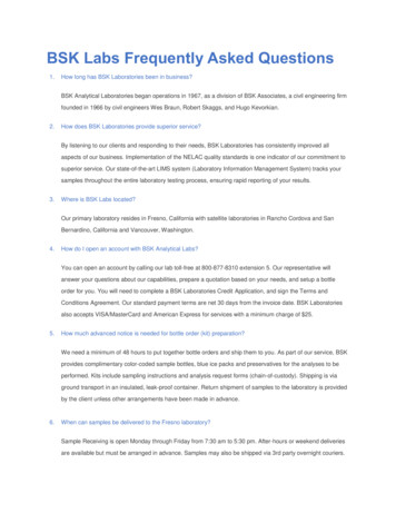
MPTA-C6m-2009FAQ ON METRIC BORES AND KEYWAYS IN COUPLINGSnumber designations have approximately the same tolerance width for a given nominalvalue.6. How do you find a tolerance class in ISO 286-1 or -2Say you were looking for 100mm H7.To obtain the tolerance values for any specific size, locate the Tolerance Class in ISO286-1. Be sure you are looking at the correct chart by matching the case of thetolerance class letter (in this case, capital H). The nominal dimensional values arelisted on the left hand side of each chart. Locate 100mm and move horizontally acrossthe chart until you intersect the appropriate tolerance width class. In this case Class 7.Record the ES and EI values listed in the chart. (The ES and EI are the tolerancevalues that should be applied to the nominal dimension; however, ES and EI are listedin micrometer. To convert to millimeters, divide each number by 1000)Note:Sometimes the ES or EI values will be the same for the entire tolerance class range.The EI for all of the H’s is the same and is only listed once at the end of the H tolerancechart. See Appendix 1 for example of ISO 287-2Example:For a 100mm H7, EI 0 and ES 35. Therefore, the actual tolerance is 100mm –0mm / .035mm or 100.00/100.035 mm.7. With so many choices in ISO 286, what sizes are appropriate to use withcouplings?ISO286 does provide a multitude of tolerance classes. There are approximately 113shaft tolerance grades and 106 bore tolerance grades listed. However this is one of thehardest questions to answer. Most of the metric standards written today try to limit thisvast number down into a set of preferred sizes. Of those preferred sizes, here aresome of the ones most commonly used on equipment shafts, keyways and couplingbores. This is not a complete list, but it is a list of sizes coupling manufacturersnormally use or see.Keyways - Js9 and P9Shafts – k6, j6, h6, m6, s6, g6, n6 and p6Bores – H7, H8, F7, P7, T7, R7, N7, M7Mechanical Power Transmission Association5672 Strand Ct., Suite 2, Naples, FL 34110www.mpta.orgPage 6 of 18
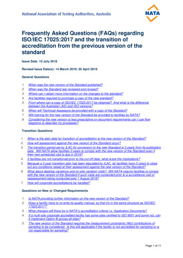
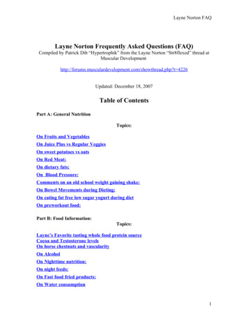
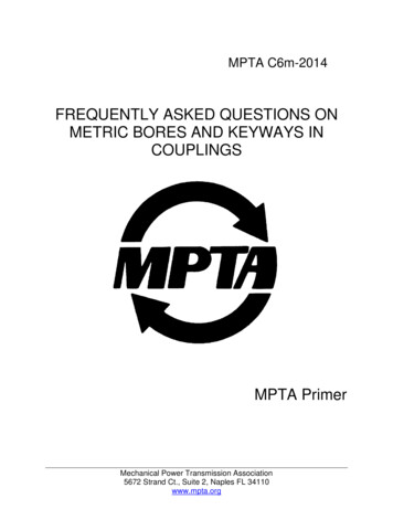
MPTA-C6m-2009FAQ ON METRIC BORES AND KEYWAYS IN COUPLINGSTable 1: Tolerance Zones for Internal DimensionsFirst choice tolerance zones shaded (per ANSI B4.2 preferred)Second choice tolerance zones framed (per ISO 1829 selected)Third choice tolerance zones S14H15JS15H16JS16Table 2: Tolerance Zones for External DimensionsFirst choice tolerance zones shaded (per ANSI B4.2 preferred)Second choice tolerance zones framed (per ISO 1829 selected)Third choice tolerance zones 16Mechanical Power Transmission Association5672 Strand Ct., Suite 2, Naples, FL 34110www.mpta.orgPage 7 of 18
MPTA-C6m-2009FAQ ON METRIC BORES AND KEYWAYS IN COUPLINGSAlthough the metric system was designed as a hole based system, the reality forcouplings is that it works more like a shaft based system. When designers aredeveloping new systems, usually main equipment such as motors, gear boxes andpumps are selected first. Couplings are normally the last items selected and thereforeneed to accommodate whatever shaft size is on the equipment. Besides, couplings aremuch easier to modify and stock.The AGMA recently surveyed many motor, gearbox and pump manufacturers fromaround the world and found the most popular shafting on that type of equipment was k6,m6 and j6. The most popular bore tolerances that correspond to those shafts are H7and P7.The actual selection depends on whether you want a clearance fit, interference fit or atransition fit between the mating components.8. When do you need a clearance fit, interference fit or a transition fit?The selection of a clearance or interference fit is influenced by several factors whichinclude; ease of assembly, system sensitivity to unbalance, available equipment and theforces generated by the operation of the coupling and equipment; i.e. gear forces,magnetic forces and deformation forces.Clearance fits seem to be the most ideal fit because of ease of assembly anddisassembly
How do you find a tolerance class in ISO 286-1 or -2 Say you were looking for 100mm H7. To obtain the tolerance values for any specific size, locate the Tolerance Class in ISO 286-1. Be sure you are looking at the correct chart by matching the case of the tolerance class letter (in this case, capital H). The nominal dimensional values are listed on the left hand side of each chart. Locate .