Transcription
IMPACTREFERENCE DESIGNORTHOGONAL DIRECT SYSTEM TOLERANCE COMPARISON ANALYSISREVISIONDESCRIPTIONINITIALDATE01Initial releasePAH3/19/2012
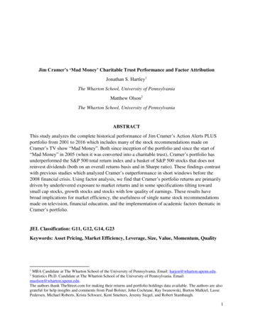
BACKGROUNDThis report is a follow-on document to the original paper “Impact Orthogonal Direct System ToleranceAnalysis, Revision: 1”. For an explanation of the tolerance analysis methodology and description ofterms please refer to that paper first. (See Appendix A)This paper answers the following question: “How does the OD connector system compare in tolerancestack up to traditional midplane systems with regards to mating boards and connectors; will connectorsmate without crashing and will there be enough engagement for adequate pin wipe?” To answer thisquestion also requires addressing the question: “What is the typical dimensional loop for computingtolerance stack up?” A card cage reference design is provided by Montie Design. Tolerance loops arecreated from this design. Analysis of the tolerance loops will measure the probability of achieving aworking assembly. By demonstrating several different tolerance loops that exist in the reference chassisdesign you will learn how to apply these techniques to your specific design. Knowing where theconstruction choices affect the tolerance build up will allow you to consider different constructiontechniques to improve your design.REFERENCE DESIGNThe card cage is a sheet metal assembly. The cage is riveted together. Proper alignment is controlled byidentifying a single locating point formating pieces; all features arecontrolled and measured from thislocating hole. Tolerances build up asdimensions from one feature to thenext string together to define theassembly process.The reference design addresses theconstruction for supporting the IO,Management, and Fabric cards only. Acomplete design will also include airflow and power supply considerations.These elements have not beenincluded in the reference design, but afew design options will be discussed.The OD design adds an air flow designoption which allows direct flow fromfront to back. The midplane can becompletely open around the IO toFigure 1 Reference Card Cage
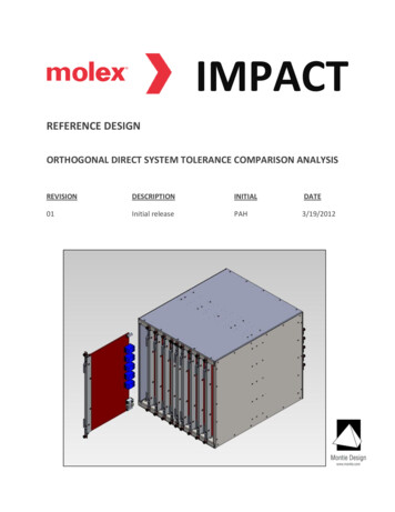
Fabric board connections. Traditional designs must create air flow paths that are separate for the frontand rear cards.How the card cage is assembled plays an important role in the dimensional loops. This design rivets thepanels together, though welding or other fasteners can also be used. Typical construction uses aligningholes and may use jigs and fixtures to support and locate panels as they are assembled. This is a furthermeans of controlling the total tolerance build up in the design.Figure 2: Card Cage, exploded viewFigure 2 shows an exploded view of the reference design. The midplane is constructed in the shape of anupside down T. Connectors on the lower section of the midplane provide communication between theManagement and the IO cards. The midplane also provides power connectors to the Management andIO cards. The vertical section of the midplane is used to provide power connection to the Fabric cards. Italso provides communication signals between the Management and Fabric cards in this referencedesign. The designer does have the option to use OD connectors for communication between theManagement and Fabric cards. The vertical section of the midplane could potentially be eliminated ifpower can be supplied to the Fabric cards via an alternate path (i.e. separate card or power buss.) In this
Figure 4: Bottom Panel subassembly, exploded viewreference design you will also see two stiffener bars,one on each side of the midplane. These providesupport against the insertion forces as cards areinserted into the midplane and also prevent the boardsfrom bowing.The midplane panel is the starting point forconstruction. Locating holes are used to alignFigure 3: Card Assembly, face plate attachmentsubassemblies as they are attached. Critical features ofeach part are controlled with respect to the locating hole. The purpose is to reduce the number ofstacked tolerances. To locate each of the panel subassemblies to the midplane panel, only one of therivet holes is a round hole, the rest are elongated to allow for tolerance variability. When the rivet isattached through this locating hole, the compression will take up all clearances and pull the two panelsinto position. Therefore, each side panel (Top, Bottom, Right and Left) is assembled to the midplanepanel in controlled position. Subassemblies follow the same construction pattern. One rivet hole is thelocating feature. Figure 3 shows how the edge guide panel is riveted to the bottom panel to build up thissubassembly. Tracing the dimension loop from feature to feature through the controlled locating holesgives the tolerance loop. Controlling dimensions to the reference locating holes reduces the number ofdimensions and tolerances that need to be considered.The card assemblies follow the same methodology. For each attached feature that is critical to thelocating function, a reference locating hole and mating pin joins the components together.TOLERANCE LOOP CONSTRUCTIONThe basic technique is to choose the connector interface to study and to find the nominal gap that isbuilt into the design. Then create a loop of the defining dimensions that run from one face all the wayaround the assembly and back to the opposite mating face. There are two sequences of matingcomponents as the boards come together. First is the initial mating of a guide pin into the mating barrelreceptacle. Second is the mating of the signal or power connectors. Each mating pair contains a
designed nominal clearance or gap to allow for tolerance variations so the parts can be assembledwithout “crashing”. The tolerance stack up results in a statistical probability around how much this gapshrinks to the point where if it becomes negative we will have an interference and failure of thecomponents to slide together.Directions will be defined as follows.X left to right when looking at the front of the chassis,Y bottom to top,Z front to back.CONNECTOR PIN ENGAGEMENTThe first tolerance study is in the Z direction, the seating of the connectors. There are two designapproaches. One is to design the cards to be inserted fully until the first connector bottoms out againstthe mating connector on the midplane or the orthogonal pair. Designing the nominal gap to be zeromeans the tolerance loop will predict interference for half of the cards. This interference will exhibititself somewhere else in the design. For example, in the reference chassis, this would show up as a gapbetween the card face plate and the front edge of the chassis edge guide panel. It is up to the designerto determine the criterion and create a design that meets these needs.The other design approach is to design in an intentional gap between the connectors as the nominaldesign condition. A larger gap lowers the probability of an interference. If the gap is too generousthough, the tolerance spread in the opposite direction would result in the connectors failing to matesufficiently. The designer needs to determine if there is enough pin length engagement left in theconnection to ensure that the electrical contact will be reliable. The designer sets the minimum amountof pin wipe allowed for thedesign and compares thisto the amount that exists inthe worst case tolerancebuild up expected. Thereference design is basedon this second approach.So to reiterate these designpoints:1. The signalcharacteristics forhigh-speedtransmissions needto be understoodand included in theFigure 5: Z Loop Definitions, connector engagement
mechanical design considerations.2. Fully seated vs. partially seated connectors and a means to secure the card to restrict movementafter insertion in the cage are inter-related design considerations.We have three dimensional loops to consider.1. IO cards as they mate with the connectors on the midplane.2. Fabric cards as they mate to the back side of the midplane.3. The orthogonal connection of the IO to the Fabric cards.In a traditional design, dimensional Loops 1 and 2 are already a common occurrence. This provides abaseline for comparisons between the reference design in this paper and the reader’s particular design.The user can compare construction techniques and tolerance parameters with his/her typicalconstruction and compare the computations for tolerance stack ups.Loop 3 is unique to the OD connection system. The following analysis shows the tolerance variations arecomparable to 1 and 2, generally falling between the two ranges.LOOP 1The first Loop study will be the mating of the IO card to the Midplane. Initially the design assumes zeronominal gap between the mating connectors on the IO Card and the Midplane. The results can be usedto see the effect of different designed gaps on the probability of interference. Figure 6 shows therelevant dimensions of the IO card assembly for the tolerance loop.D1 connector dimension from the mating face to the location of P1. Since the pins are a pressfit into the board, there are no hole clearance dimensions included.D2 P1 location to the reference locating hole for the PCB to the Face Plate. In this case theassembly could be a clearance fit around the pin to hole in the face plate. This clearance isincluded as an added tolerance.D3 distance from the locating hole on the face plate to the locating surface of the face platethat is screwed against the front of the edge guide panel.The dimensional loop now moves to the Edge Guide panel subassembly.D4 distance from front folded edge to the locating reference hole that attaches to the toppanel. Assume all clearance is taken up by the rivet, so no tolerance is necessary for theclearance.D5 distance from the edge guides’ locating hole in the top panel to the locating hole for themidplane panel. Again, no clearance will be left after the rivet is clinched.
Figure 6: LOOP 1 DimensionsNext we traverse to the midplane panel subassembly, including the midplane PCB.D6 distance from the locating hole on the top bend of the midplane panel to the face of themidplane panel. The Midplane PCB will be secured against this face so it is the reference surface.D7 the dimension of the mating connector, from the surface against the PCB to the matingface inside the connector. There will be a dimensional tolerance. Also, there will be a tolerancefor the variability that represents the connector not fully seated against the board.
For a better view of the locating dimensions on the bottom panel, see Figure 7.Figure 7: Loop 1 Bottom panel dimensionsThat completes the loop. Tables 1-3 show the computation results. Look at the calculations to see howthe tolerances stack up and to see where to set the nominal gap.In the first calculation with a designed gap of zero, the computed tolerance sigma is 0.14mm. A goodcomputation point would thus be a nominal gap of 0.5mm. The nominal gap should also be chosen bylooking at the total pin wipe available. Impact connectors will have up to 2mm of wipe, so a nominal gapof 0.5mm is still a reasonable design point.Table 1: LOOP 1, no gapLOOP 1DimD1D2D3D4D5D6D7IO CARD to MIDPLANE INTERFACEGap 0Descriptionmating face of connector to P1P1 to locating hole for face platelocating hole clearance between PCA and faceplateLocating hole of face plate to locating surfaceTop edge guide panel front face to locating holewith Top Panellocating hole for edge guide to locating hole formidplane panel on bottom panellocating hole to face of midplane panelconnector mating face distance above pcbNom11.36222.55σMeanTol /- Shift0.081.50.121.5V-1-1MeanMeanCentered ShiftedCalcCalc-11.360 -11.387-222.550 -222.590MeanMeanCentered Centered MeanMeanσσ²Shifted σ Shifted σ²0.02667 0.00071 0.01778 0.000320.04000 0.00160 0.02667 0120.009Nominal Gap 0.000Sigma 0.1403 sigma 0.42111-1GnomCentered MeanDesign Sigma0.000Probability 50.00%PPM 500000Shifted MeanDesign Sigma-3.555Probability 99.98%PPM 999811
If you look at the probability of interference, you see the calculation is 50%. This is because the nominalgap is zero. Half of the time the tolerances will be greater than zero; half of the time less than zero.Open the gap to get the probability or parts per million (PPM) down to an acceptable number.Tables 2 and 3 show the computations if the design included a nominal gap of 0.5 and 1.0mm by makingthe PCB shorter (D2). Look at the results for the probability of interference.Table 2: LOOP 1, 0.5mm gapLOOP 1 IO CARD to MIDPLANE INTERFACEDimD1D2D3D4D5D6D7Gap 0.5DescriptionConnector P1 to Locating hole from PCA to FacePlateConnector P1 to connector mating facelocating hole clearance between PCA and faceplateLocating hole of face plate to locating surfaceTop edge guide panel front face to locating holewith Top Panellocating hole to locating hole on bottom panellocating hole to face of midplane panelconnector mating face distance above pcbNomσMeanTol /- ShiftVMeanCenteredCalc-11.360 -11.387-222.050 .001.51.51.51.5Nominal Gap 0.500Sigma 0.1403 sigma 0.421111-1GnomMeanShiftedCalcMeanMeanCentered Centered MeanMeanσσ²Shifted σ Shifted 003090.000710.003090.000120.009Centered MeanDesign Sigma3.564Probability 0.02%PPM183Shifted MeanDesign Sigma1.791Probability3.67%PPM36662Table 3: LOOP 1, 1.0mm gapLOOP 1 IO CARD to MIDPLANE INTERFACEDimD1D2D3D4D5D6D7Gap 1.0DescriptionConnector P1 to Locating hole from PCA to FacePlateConnector P1 to connector mating facelocating hole clearance between PCA and faceplateLocating hole of face plate to locating surfaceTop edge guide panel front face to locating holewith Top Panellocating hole to locating hole on bottom panellocating hole to face of midplane panelconnector mating face distance above pcbNomσMeanTol /- ShiftVMeanCenteredCalc-11.360 -11.387-221.550 .001.51.51.51.5Nominal Gap 1.000Sigma 0.1403 sigma 0.421111-1GnomMeanShiftedCalcMeanMeanCentered Centered MeanMeanσσ²Shifted σ Shifted 003090.000710.003090.000120.009Centered MeanDesign Sigma7.128Probability 0.00%PPM0Shifted MeanDesign Sigma7.137Probability0.00%PPM0
With a 0.5mm nominal gap, the probability of interference (bottoming out) is down to 0.02% (183PPM);at a 1.0mm nominal gap, the probability shrinks to essentially zero. What about too much gap?At the other end of the tolerance stack up, the question is whether there will be enough pinengagement for a reliable connection. For example, using the 5.5mm pin length Impact connectorsprovides a maximum pin wipe of 2.0mm. At the maximum probable gap (nominal gap plus 3 sigma) theminimum amount of pin wipe will be the total pin wipe minus the nominal gap minus 3 times thetolerance standard deviation (3 sigma). For 0.5mm nominal gap the computed minimum pin wipe is 20.5-0.421 1.079mm. For 1.0mm nominal gap the minimum pin wipe is only 0.579mm Using thisapproach, a designed nominal gap of 1mm will not provide the desired pin engagement.Figure 8: Loop 2 configurationLOOP 2Loop 2 is similar to Loop 1, but adds in the midplane board thickness. In this loop, the mating connectoris on the back side of the Midplane PCB; the dimension loop for the midplane goes from top face of thePCB to the back side (board thickness). The mating connector is on the back side of the PCB. Loop 2consists of all the dimensions in Loop 1 plus one added dimension of the midplane PCB thickness. Actual
dimensions will vary depending on the design of the fabric card sizes and depth of the card cage, but theassociated tolerances will be similar. You will note that in this loop, the manufacturing tolerance of theboard thickness is a significant component of the total tolerance, and is much larger than any otherdimensional tolerance. The card thickness tolerance is typically /- 10% so the thicker the board, thelarger the tolerance. The reference design assumes a 6.45mm thick midplane. A thicker board providesmore stiffness and layers for routing signals. A thinner board will have less tolerance, so the designersneed to balance these factors in selecting the design thickness of the midplane. Generally, the electricalcharacteristics will take precedence over mechanical properties.Beginning at the Fabric card connector:R1 connector dimension from the mating face to the location of P1. Since the pins are a pressfit into the board, we don’t need to include any hole clearance in the study.R2 P1 location to the reference locating hole for the PCB to the Face Plate. In this case theassembly could be a clearance fit around the pin to hole in the face plate. We need to includethis clearance as an added tolerance.R3 distance from the locating hole on the face plate to the locating surface of the face platethat is screwed against the front of the edge guide panel. The face plate is screwed fast againstthe edge rail, so there will be no clearance.Next move to the Side Panel dimensions:R4 distance from front face of edge rail to the locating reference hole that attaches the rail tothe side panel. We assume that the counter sink head will hold the parts in location, so thetolerance is not for clearance, but is for concentricity of screw head to shank.R5 distance from the edge guide’s locating hole in the side panel to the locating hole for themidplane panel. Again no clearance will be left after the rivet is clinchedEnd with the Midplane panel and the Midplane PCB.R6 distance from the locating hole on the side bend of the midplane panel to the face of themidplane panel. The Midplane PCB will be secured against this face so it is the reference surface.R7 the dimension of the mating connector, from the surface against the PCB to the matingface inside the connector. There will be a dimensional tolerance. Also, there will be a tolerancefor the variability that represents the connector not fully seated against the board.R8 thickness of midplane PCB. In the loop, R8 comes before R7. For computation purposesthis doesn’t matter.
Figure 9: LOOP 2 dimensions
Figure 10: Loop 2 dimensions, close up views
Figure 11: Loop 2, Side Panel dimensions
Tables 4 and 5 show the results of the analysis for Loop 2 with a 0.5mm and 1.0mm nominal gap.Table 4: LOOP 2 analysis, 0.5mm gapLOOP 2 Fabric card to Back side of MidplaneDimR1R2R3R4R5R6R7R8GGap 0.5OD RAM connector mating face to P1 locationP1 location to PCB locating hold for face plateclearance around locating holelocating hole to locating face on Face PlateFace of edge rail to mounting hole on side panelmounting hole on side panel to locating hole forMidplane paneldistance from locating hole to front face ofMidplane panelConnector mating face distance off face of PCAthickness of Midplane PCBdesigned gapNom11.36220.650.0013.0010.16σMeanTol /- .5Nominal Gap 0.500Sigma 0.2433 sigma 0.730V-1-1-1-111-1-1-11GnomMeanMeanCentered ShiftedCalcCalc-11.360 -11.387-220.650 -220.6900.000-0.003-13.000 -13.04010.16010.120MeanMeanCentered Centered MeanMeanσσ²Shifted σ Shifted σ²0.02667 0.00071 0.01778 0.000320.04000 0.00160 0.02667 0.000710.00250 0.00001 0.00167 0.000000.04000 0.00160 0.02667 0.000710.04000 0.00160 0.02667 000.1620.003090.000120.019910.000000.026Centered MeanDesign Sigma2.056Probability 1.99%PPM 19892Shifted MeanDesign Sigma-0.005Probability 50.21%PPM 502051Table 5: LOOP 2 analysis, 1.0mm gapLOOP 2 Fabric card to Back side of MidplaneDimR1R2R3R4R5R6R7R8GGap 1.0OD RAM connector mating face to P1 locationP1 location to PCB locating hole for face plateclearance around locating holelocating hole to locating face on Face PlateFace of edge rail to mounting hole on side panelmounting hole on side panel to locating hole forMidplane paneldistance from locating hole to front face ofMidplane panelConnector mating face distance off face of PCAthickness of Midplane PCBdesigned gapNom11.36220.650.0013.0010.16σMeanTol /- .5Nominal Gap 1.000Sigma 0.2433 sigma 0.730V-1-1-1-111-1-1-11GnomMeanMeanCentered ShiftedCalcCalc-11.360 -11.387-220.650 -220.6900.000-0.003-13.000 -13.04010.16010.120MeanMeanCentered Centered MeanMeanσσ²Shifted σ Shifted σ²0.02667 0.00071 0.01778 0.000320.04000 0.00160 0.02667 0.000710.00250 0.00001 0.00167 0.000000.04000 0.00160 0.02667 0.000710.04000 0.00160 0.02667 00.1620.003090.000120.019910.000000.026Centered MeanDesign Sigma4.112Probability 0.00%PPM20Shifted MeanDesign Sigma3.079Probability0.10%PPM1039With these two analyses (Loop 1 and Loop 2) we have described the tolerance conditions of the typicalmidplane chassis design in use today. Loop 2 shows that the midplane thickness is the gating factor indetermining how large of a nominal gap is required and how much pin wipe can be guaranteed. At
0.5mm, the probability of crashing is 1.99% or 19892PPM, a significant risk. At 1.0mm nominal gap, theprobability drops to near zero or 20PPM. The 3 sigma tolerance variation on the rear side of themidplane increases from 0.421mm to 0.730mm. Subtracted from the total pin wipe (2.0mm) leaves1.270mm available and subtracting a nominal gap of 0.5mm then estimates the guaranteed pin wipewould be 0.77mm. Today’s chassis designs solve this problem in a variety of ways. One is to reduce themidplane thickness. Changing the midplane from 6.35 to 3.18mm thick will improve the probability to0.09% (885PPM). Another method is to use fixtures during the assembly of the chassis to set the edgeguide panels a fixed distance from the front and rear face of the midplane. This takes a number of thetolerances out of the loop and tightens the overall tolerance variation.LOOP 3Figure 12: Loop 3 featuresMating of the OD Impact connectors is defined by Loop 3. The dimension loop is composed of a partialcombination of dimensions from Loop 1 and 2. From Loop 1, the dimensions are from the OD RAFconnector face on the IO PCB through the face plate to the Edge guide panel and top cover and end atthe locating hole for the midplane panel. Skip any dimensions related to the Midplane PCB and go toLoop 2 dimensions. Continue with the locating hole for the side panel and travelling backwards to theedge guide rail then face plate of the Fabric card and end with the mating face of the OD RAMconnector. See the dimension loop below.
Loop 3: IO to Fabric card mating connectors.D1 OD RAF connector mating face to P1 locationD2 P1 location to PCB locating hole for Face Plate. Include hole to pin clearance in tolerance.D3 locating hole to locating face on face plate. Face is fastened to edge guideD4 Face of edge guide to locating hole for top panelD5 locating hole for edge guide to locating hole for midplane in top panelTransition Positional shift from top flange of midplane to the side flange. The dimension in the study iszero, but there is a tolerance associated in the transition from hole to hole as the dimensional loopmoves from the top to the side panel.R5 mounting hold on side panel to locating hole for Midplane panel.R4 Face of edge rail to mounting hole on side panelR3 locating hole to locating face on face plate. Face is fastened to edge railR2’ P1 location to PCB locating hole for Face Plate. Include hole to pin clearance in tolerance.R1’ OD RAM connector mating face to P1 locationThe actual dimension values for R1’ and R2’ (shown in Figure 9) change to represent the OD RAMconnector instead of the Midplane connector, but the tolerances remain the same. This loop has themost dimensions and thus will have the most tolerances to accommodate, though the computedprobability is comparable to Loop 1. The probability of bottoming out is 0.09% (870 PPM). The minimumpin wipe is computed as 2.0-.5-.489 1.011mm.These analyses thus demonstrate that designing an ODconnector system will be just as reliable as the typical midplane chassis design in production today.
Table 6: LOOP 3 analysis, 0.5mm gapLOOP 3 OD RAF to RAM connectionDimD1D2D3D4D5TR1'R2'R3R4R5Gmating face of RAF connector to P1P1 to locating hole for face platelocating hole clearance between PCA and faceplateLocating hole of face plate to locating surfaceTop edge guide panel front face to locating holewith Top Panellocating hole for edge guide to locating hole formidplane panel on bottom paneltransition from side panel to top panelOD RAM connector mating face to P1 locationP1 location to PCB locating hole for face plateclearance around locating holelocating hole to locating face on Face PlateFace of edge rail to mounting hole on side panelmounting hole on side panel to locating hole forMidplane paneldesigned gapNom11.36222.55σMeanTol /- Shift0.081.50.121.5V-1-1MeanMeanCentered ShiftedCalcCalc-11.360 -11.387-222.550 -222.590MeanMeanCentered Centered MeanMeanσσ²Shifted σ Shifted σ²0.02667 0.00071 0.01778 0.000320.04000 0.00160 0.02667 1-1-1-1-11231.780 231.7400.000-0.083-14.380 -14.407-229.250 -229.2900.000-0.003-13.000 .000000.0121.52Nominal Gap 0.510Sigma 0.1633 sigma 0.48911Gnom256.5400.5000.510Centered MeanDesign Sigma3.132Probability 0.09%PPM870256.5000.5000.005Shifted MeanDesign Sigma0.046Probability 48.16%PPM 481635LATERAL CONNECTOR MATINGNow, turn your attention to the other two directional loops (X and Y). These follow the traditional designparameters and considerations. The tolerance stacks for the traditional midplane design and the ODdesign are similar. It is instructive to go through the tolerance loops so you can see how this is done andapply it to your particular design.Here is a partial list of cage design choices.The main potential for a large variability in this analysis comes from the potential bowing of the PCB,especially if it is a large card or has heavy components installed. Designers will take typical measures tokeep the board relatively flat by using a thicker PCB or adding mechanical stiffening to the board. In thecase of a wide board, the designer also has the option of using integrated guide pins in the ODConnector or adding a standalone guide pin in the center of the board for additional support andguidance. These are choices for the designer to make.Are the guide pins mounted to the midplane sheet metal panel or the midplane PCB? Does it make adifference? Does it make a difference if you use integrated or stand-alone guide pins? All of these havea minimal impact on the tolerance question. This will be shown in the analysis below. As the cards cometogether, there is a series of transitions; which components provide the guidance and locating featuresfor proper mating. The first to mate are the guide pins, and they have the largest range of clearance toengage. Therefore the small tolerance associated with the mounting style has a minimal impact. See the
analysis below for details. As the guide pins direct the cards into alignment, the tallest connectors thenbegin to engage and take over the locating function since they have a tighter clearance for mating.Finally, the shorter connectors are engaged. Since guide pins and connector mating has beensuccessfully used in the industry, we can conclude that with proper design, if the taller connectors mateproperly then all the connectors will mate without issue. There isn’t a lot of clearance in the guidereceptacles, but it is enough to allow all of the connectors to float and mate within their respectivetolerance fields. Part of this comes from the compliance of the connector systems. From this we canassume if the connectors are close enough to mate within their tolerance system, then after mating, theguide pins are no longer the sole source in controlling the location of components, but just another setof components in the total connector system which has reached a positional equilibrium of clearancesand compliance.The ortho direct connectors allow you to remove the midplane from the design around this
Mar 19, 2012 · The user can compare construction techniques and tolerance parameters with his/her typical construction and compare the computations for tolerance stack ups. Loop 3 is unique to the OD connection system. The following analysis shows the tolerance variations are comparable to