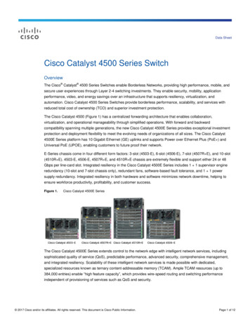
Transcription
CH A P T E R5Managing Switch StacksThis chapter provides the concepts and procedures to manage Catalyst 3750-X switch stacks.NoteThe LAN base feature set supports switch stacks only when all switches in the stack are run the LANbase feature set.The switch command reference has command syntax and usage information.This chapter consists of these sections: Restrictions for Switch Stacks, page 5-1 Understanding Switch Stacks, page 5-2 Configuring the Switch Stack, page 5-20 Accessing the CLI of a Specific Stack Member, page 5-25 Displaying Switch Stack Information, page 5-25 Troubleshooting Stacks, page 5-25For other switch stack-related information, such as cabling the switches through their StackWise Plusports and using the LEDs to display switch stack status, see the hardware installation guide.The Catalyst 3750-X stackable switch also supports StackPower, where up to four switches can beconnected with power stack cables to allow the switch power supplies to share the load across multiplesystems in a stack. Switches in a power stack must be members of the same switch (data) stack. Forinformation about StackPower, see Chapter 9, “Configuring Catalyst 3750-X StackPower.”NoteThis chapter describes how to manage Catalyst 3750-X-only switch stacks. For information aboutmanaging hardware and software stacks and about using universal software images with softwarelicenses, see the Cisco IOS Software Installation document on Cisco.com.Restrictions for Switch StacksAfter changing a virtual routing and forwarding (VRF) configuration, followed by the switchover of themaster switch, can cause the VRF functionality to not work correctly. Reload the entire switch stack afterthe VRF configuration change for the VRF functionality to work correctly after a switchover. That is,change the VRF configuration, save the configuration, and reload the entire switch stack.Catalyst 3750-X and 3560-X Switch Software Configuration GuideOL-21521-025-1
Chapter 5Managing Switch StacksUnderstanding Switch StacksUnderstanding Switch StacksA switch stack is a set of up to nine stacking-capable switches connected through their StackWise Plusor StackWise ports. You can connect only one switch type in a stack, or you can connect a mix ofCatalyst 3750-X, Catalyst 3750-E, and Catalyst 3750 switches in the stack. Catalyst 3750-X andCatalyst 3750-E stack members have StackWise Plus ports, and Catalyst 3750 members have StackWiseports. The stack can have one of these configurations: Homogeneous stack—A Catalyst 3750-E-only stack with only Catalyst 3750-E switches as stackmembers or a Catalyst 3750-X-only stack with only Catalyst 3750-X switches as stack members. Mixed stackNoteMixed stacks are not supported with switches running the LAN base feature set.– A mixed hardware stack with a mixture of Catalyst 3750-X, Catalyst 3750-E, and 3750 switchesas stack members.For example, a stack with Catalyst 3750-X and 3750 switches supporting the IP servicesfeatures.– A mixed software stack with only Catalyst 3750-X, only Catalyst 3750-E, or only Catalyst 3750switches supporting different features as stack members.For example, a Catalyst 3750-X-only stack with some members running the IP base feature set,other members running the IP services feature set, and the remaining members running the IPservices feature set.– A mixed hardware and software stack with Catalyst 3750-X, Catalyst 3750-E, andCatalyst 3750 switches supporting different features as stack members.For example, a stack with the Catalyst 3750-X members running the IP services feature set andthe Catalyst 3750 members running the IP services software image.For information about Catalyst 3750 switches, see the “Managing Switch Stacks” chapter in theCatalyst 3750 Switch Software Configuration Guide.One of the switches controls the operation of the stack and is called the stack master. The stack masterand the other switches in the stack are all stack members. The Catalyst 3750-E stack members use theCisco StackWise Plus technology to work together as a unified system. Layer 2 and Layer 3 protocolspresent the entire switch stack as a single entity to the network.NoteSwitch stacks running the LAN base feature set do not support Layer 3 features.The stack master is the single point of stack-wide management. From the stack master, you configure: System-level (global) features that apply to all stack members Interface-level features for each stack memberA switch stack is identified in the network by its bridge ID and, if it is operating as a Layer 3 device, itsrouter MAC address. The bridge ID and router MAC address are determined by the MAC address of thestack master. Every stack member is identified by its own stack member number.All stack members are eligible to be stack masters. If the stack master becomes unavailable, theremaining stack members elect a new stack master from among themselves. The switch with the higheststack member priority value becomes the new stack master.Catalyst 3750-X and 3560-X Switch Software Configuration Guide5-2OL-21521-02
Chapter 5Managing Switch StacksUnderstanding Switch StacksThe system-level features supported on the stack master are supported on the entire switch stack. If aswitch in the stack is running the IP base or IP services feature set and the cryptographic (that is,supporting encryption) universal software image, we recommend that this switch be the stack master.Encryption features are unavailable if the stack master is running the IP base or IP services feature setand the noncryptographic software image.NoteIn a mixed stack, Catalyst 3750 or Catalyst 3750-E switches running Cisco IOS Release 12.2(53)SE andearlier could be running a noncryptographic image. Catalyst 3750-X switches and Catalyst 3750 and3750-E switches with Cisco IOS Releases later than 12.2(53)SE run only the cryptographic softwareimage.The stack master contains the saved and running configuration files for the switch stack. Theconfiguration files include the system-level settings for the switch stack and the interface-level settingsfor each stack member. Each stack member has a current copy of these files for back-up purposes.You manage the switch stack through a single IP address. The IP address is a system-level setting and isnot specific to the stack master or to any other stack member. You can manage the stack through the sameIP address even if you remove the stack master or any other stack member from the stack.You can use these methods to manage switch stacks: Network Assistant (available on Cisco.com) Command-line interface (CLI) over a serial connection to the console port of any stack member orthe Ethernet management port of a stack member A network management application through the Simple Network Management Protocol (SNMP)Use SNMP to manage network features across the switch stack that are defined by supported MIBs.The switch does not support MIBs to manage stacking-specific features such as stack membershipand election. CiscoWorks network management softwareTo manage switch stacks, you should understand: These concepts on how switch stacks are formed:– Switch Stack Membership, page 5-4– Stack Master Election and Re-Election, page 5-5 These concepts on how switch stacks and stack members are configured:– Switch Stack Bridge ID and Router MAC Address, page 5-7– Stack Member Numbers, page 5-7– Stack Member Priority Values, page 5-8– Switch Stack Offline Configuration, page 5-8– Hardware Compatibility and SDM Mismatch Mode in Switch Stacks, page 5-10– Switch Stack Software Compatibility Recommendations, page 5-11– Stack Protocol Version Compatibility, page 5-11– Major Version Number Incompatibility Among Switches, page 5-11– Minor Version Number Incompatibility Among Switches, page 5-12– Incompatible Software and Stack Member Image Upgrades, page 5-15– Switch Stack Configuration Files, page 5-15Catalyst 3750-X and 3560-X Switch Software Configuration GuideOL-21521-025-3
Chapter 5Managing Switch StacksUnderstanding Switch Stacks– Additional Considerations for System-Wide Configuration on Switch Stacks, page 5-16– Switch Stack Management Connectivity, page 5-17– Switch Stack Configuration Scenarios, page 5-18NoteA switch stack is different from a switch cluster. A switch cluster is a set of switches connected throughtheir LAN ports, such as the 10/100/1000 ports. For more information about how switch stacks differfrom switch clusters, see the “Planning and Creating Clusters” chapter in the Getting Started with CiscoNetwork Assistant on Cisco.com.Switch Stack MembershipA switch stack has up to nine stack members connected through their StackWise Plus ports. A switchstack always has one stack master.A standalone switch is a switch stack with one stack member that also operates as the stack master. Youcan connect one standalone switch to another (Figure 5-1 on page 5-5) to create a switch stackcontaining two stack members, with one of them as the stack master. You can connect standaloneswitches to an existing switch stack (Figure 5-2 on page 5-5) to increase the stack membership.If you replace a stack member with an identical model, the new switch functions with exactly the sameconfiguration as the replaced switch, assuming that the new switch is using the same member number asthe replaced switch. For information about the benefits of provisioning a switch stack, see the “SwitchStack Offline Configuration” section on page 5-8. For information about replacing a failed switch, seethe “Troubleshooting” chapter in the hardware installation guide.The operation of the switch stack continues uninterrupted during membership changes unless youremove the stack master or you add powered-on standalone switches or switch stacks.NoteMake sure that you power off the switches that you add to or remove from the switch stack.After adding or removing stack members, make sure that the switch stack is operating at full bandwidth(64 Gb/s). Press the Mode button on a stack member until the Stack mode LED is on. The last two rightport LEDs on all switches in the stack should be green. Depending on the switch model, the last tworight ports are 10-Gigabit Ethernet ports or small form-factor pluggable (SFP) module ports(10/100/1000 ports). If one or both of these LEDs are not green on any of the switches, the stack is notoperating at full bandwidth. Adding powered-on switches (merging) causes the stack masters of the merging switch stacks toelect a stack master from among themselves. The re-elected stack master retains its role andconfiguration and so do its stack members. All remaining switches, including the former stackmasters, reload and join the switch stack as stack members. They change their stack membernumbers to the lowest available numbers and use the stack configuration of the re-elected stackmaster. Removing powered-on stack members causes the switch stack to divide (partition) into two or moreswitch stacks, each with the same configuration. This can cause an IP address configuration conflictin your network. If you want the switch stacks to remain separate, change the IP address or addressesof the newly created switch stacks. If you did not intend to partition the switch stack:a. Power off the switches in the newly created switch stacks.b. Reconnect them to the original switch stack through their StackWise Plus ports.c. Power on the switches.Catalyst 3750-X and 3560-X Switch Software Configuration Guide5-4OL-21521-02
Chapter 5Managing Switch StacksUnderstanding Switch StacksFor more information about cabling and powering switch stacks, see the “Switch Installation” chapter inthe hardware installation guide.Figure 5-1Creating a Switch Stack from Two Standalone SwitchesStack member 1Stack member 1Stack member 2and stack masterFigure 5-2157552Stack member 1Adding a Standalone Switch to a Switch StackStack member 1Stack member 2and stack masterStack member 3Stack member 1Stack member 1Stack member 3Stack member 4157553Stack member 2and stack masterStack Master Election and Re-ElectionThe stack master is elected or re-elected based on one of these factors and in the order listed:1.The switch that is currently the stack master.2.The switch with the highest stack member priority value.Note3.We recommend assigning the highest priority value to the switch that you prefer to be thestack master. This ensures that the switch is re-elected as stack master if a re-election occurs.The switch that is not using the default interface-level configuration.Catalyst 3750-X and 3560-X Switch Software Configuration GuideOL-21521-025-5
Chapter 5Managing Switch StacksUnderstanding Switch Stacks4.NoteThe switch with the higher priority feature set and software image combination. These combinationsare listed from highest to lowest priority.The noncryptographic images apply only to mixed stacks that include Catalyst 3750-E or 3750switches running Cisco IOS Release 12.2(53)SE or earlier. Catalyst 3750-X switches andCatalyst 3750-E or 3750 switches running later releases support only the cryptographic image.– IP services feature set and the cryptographic software image– IP services feature set and the noncryptographic software image– IP base feature set and the cryptographic software image– IP base feature set and the noncryptographic software imageNoteIn a switch stacks running the LAN base feature set, all switches in the stack must run the LANbase feature set.During the stack master switch election, differences in start-up times between the feature setsdetermine the stack master. The switch with the shorter start-up time becomes the stack master.For example, a switch running the IP services feature set has a higher priority than the switchrunning the IP base feature set, but the switch running the IP base feature set becomes the stackmaster because the other switch takes 10 seconds longer to start. To avoid this problem, upgrade theswitch running the IP base feature set to same feature set and software image as the other switch, ormanually start the master switch and wait at least 8 seconds before starting the new member switchthat running the IP base feature set.5.The switch with the lowest MAC address.A stack master retains its role unless one of these events occurs: The switch stack is reset.* The stack master is removed from the switch stack. The stack master is reset or powered off. The stack master fails. The switch stack membership is increased by adding powered-on standalone switches or switchstacks.*In the events marked by an asterisk (*), the current stack master might be re-elected based on the listedfactors.When you power on or reset an entire switch stack, some stack members might not participate in thestack master election. Stack members that are powered on within the same 20-second time frameparticipate in the stack master election and have a chance to become the stack master. Stack membersthat are powered on after the 20-second time frame do not participate in this initial election and becomestack members. All stack members participate in re-elections. For all powering considerations that affectstack-master elections, see the “Switch Installation” chapter in the hardware installation guide.The new stack master becomes available after a few seconds. In the meantime, the switch stack uses theforwarding tables in memory to minimize network disruption. The physical interfaces on the otheravailable stack members are not affected during a new stack master election and reset.After a new stack master is elected and the previous stack master becomes available, the previous stackmaster does not resume its role as stack master.Catalyst 3750-X and 3560-X Switch Software Configuration Guide5-6OL-21521-02
Chapter 5Managing Switch StacksUnderstanding Switch StacksAs described in the hardware installation guide, you can use the Master LED on the switch to see if theswitch is the stack master.Switch Stack Bridge ID and Router MAC AddressThe bridge ID and router MAC address identify the switch stack in the network. When the switch stackinitializes, the MAC address of the stack master determines the bridge ID and router MAC address.If the stack master changes, the MAC address of the new stack master determines the new bridge ID androuter MAC address. However, when the persistent MAC address feature is enabled, the stack MACaddress changes in approximately 4 minutes. During this time period, if the previous stack master rejoinsthe stack, the stack continues to use its MAC address as the stack MAC address, even if the switch isnow a stack member and not a stack master. If the previous stack master does not rejoin the stack duringthis period, the switch stack takes the MAC address of the new stack master as the stack MAC address.See Enabling Persistent MAC Address, page 5-20 for more information.Stack Member NumbersThe stack member number (1 to 9) identifies each member in the switch stack. The member number alsodetermines the interface-level configuration that a stack member uses. You can display the stack membernumber by using the show switch user EXEC command.A new, out-of-the-box switch (one that has not joined a switch stack or has not been manually assigneda stack member number) ships with a default stack member number of 1. When it joins a switch stack,its default stack member number changes to the lowest available member number in the stack.Stack members in the same switch stack cannot have the same stack member number. Every stackmember, including a standalone switch, retains its member number until you manually change thenumber or unless the number is already being used by another member in the stack. If you manually change the stack member number by using the switchcurrent-stack-member-number renumber new-stack-member-number global configurationcommand, the new number goes into effect after that stack member resets (or after you use thereload slot stack-member-number privileged EXEC command) and only if that number is notalready assigned to any other members in the stack. For more information, see the “Assigning aStack Member Number” section on page 5-22. Another way to change the stack member number isby changing the SWITCH NUMBER environment variable, as explained in the “ControllingEnvironment Variables” section on page 3-21.If the number is being used by another member in the stack, the switch selects the lowest availablenumber in the stack.If you manually change the number of a stack member and no interface-level configuration isassociated with that new member number, that stack member resets to its default configuration. Formore information about stack member numbers and configurations, see the “Switch StackConfiguration Files” section on page 5-15.You cannot use the switch current-stack-member-number renumber new-stack-member-numberglobal configuration command on a provisioned switch. If you do, the command is rejected. If you move a stack member to a different switch stack, the stack member retains its number only ifthe number is not being used by another member in the stack. If it is being used, the switch selectsthe lowest available number in the stack.Catalyst 3750-X and 3560-X Switch Software Configuration GuideOL-21521-025-7
Chapter 5Managing Switch StacksUnderstanding Switch Stacks If you merge switch stacks, the switches that join the switch stack of a new stack master select thethe lowest available numbers in the stack. For more information about merging switch stacks, seethe “Switch Stack Membership” section on page 5-4.As described in the hardware installation guide, you can use the switch port LEDs in Stack mode tovisually determine the stack member number of each stack member.Stack Member Priority ValuesA higher priority value for a stack member increases its likelihood of being elected stack master andretaining its stack member number. The priority value can be 1 to 15. The default priority value is 1. Youcan display the stack member priority value by using the show switch user EXEC
Catalyst 3750 Switch Software Configuration Guide. One of the switches controls the operation of the stack and is called the stack master. The stack master and the other switches in the stack are all stack members. The Catalyst 3750-E stack members use the Cisco StackWise Plus

