Transcription
SolidWorks Tutorial 10DRAWING OF THE AXLE SUPPORTPreparatory Vocational Trainingand Advanced Vocational TrainingTo be used with SolidWorks Educational Edition Release 2008-2009
1995-2009, Dassault Systèmes SolidWorks Corp.300 Baker AvenueConcord, Massachusetts 01742 USAAll Rights Reserved.U.S. Patents 5,815,154; 6,219,049; 6,219,055Dassault Systèmes SolidWorks Corp.is a Dassault SystèmesS.A. (Nasdaq:DASTY) company.The information and the software discussed in this documentare subject to change without notice and should not be considered commitments by Dassault Systèmes SolidWorks Corp.No material may be reproduced or transmitted in any form orby any means, electronic or mechanical, for any purposewithout the express written permission of Dassault SystèmesSolidWorks Corp.The software discussed in this document is furnished under alicense and may be used or copied only in accordance withthe terms of this license. All warranties given by DassaultSystèmes SolidWorks Corp. as to the software and documentation are set forth in the Dassault Systèmes SolidWorksCorp. License and Subscription Service Agreement, andnothing stated in, or implied by, this document or its contentsshall be considered or deemed a modification or amendmentof such warranties.SolidWorks is a registered trademark of Dassault SystèmesSolidWorks Corp.SolidWorks 2005 is a product name of Dassault Systèmes SolidWorks Corp.FeatureManager is a jointly owned registered trademark ofDassault Systèmes SolidWorks Corp.Feature Palette and PhotoWorks are trademarks of Dassault Systèmes SolidWorks Corp.ACIS is a registered trademark of Spatial Corporation.FeatureWorks is a registered trademark of Geometric Software Solutions Co. Limited.GLOBEtrotter and FLEXlm are registered trademarks ofGlobetrotter Software, Inc.Other brand or product names are trademarks or registeredtrademarks of their respective holders.COMMERCIAL COMPUTERSOFTWARE - PROPRIETARYU.S. Government Restricted Rights. Use, duplication, or disclosure by the government is subject to restrictions as setforth in FAR 52.227-19 (Commercial Computer Software Restricted Rights), DFARS 227.7202 (Commercial Computer Software and Commercial Computer Software Documentation), and in the license agreement, as applicable.Contractor/Manufacturer:Dassault Systèmes SolidWorks Corp., 300 Baker Avenue,Concord, Massachusetts 01742 USAPortions of this software are copyrighted by and are theproperty of Electronic Data Systems Corporation or its subsidiaries, Copyright 2009Portions of this software 1999, 2002-2009 ComponentOnePortions of this software 1990-2009 D-Cubed Limited.Portions of this product are distributed under license fromDC Micro Development, Copyright 1994-2009 DC MicroDevelopment, Inc. All Rights Reserved.Portions eHelp Corporation. All Rights Reserved.Portions of this software 1998-2009Geometric SoftwareSolutions Co. Limited.Portions of this software 1986-2009 mental images GmbH& Co. KGPortions of this software 1996-2009 Microsoft Corporation. All Rights Reserved.Portions of this software 2009, SIMULOG.Portions of this software 1995-2009 Spatial Corporation.Portions of this software 2009, Structural Research &Analysis Corp.Portions of this software 1997-2009 Tech Soft America.Portions of this software 1999-2009 Viewpoint Corporation.Portions of this software 1994-2009, Visual Kinematics,Inc.All Rights Reserved.SolidWorks Benelux developed this tutorial for self-training with the SolidWorks 3D CAD program. Any other useof this tutorial or parts of it is prohibited. For questions, please contact SolidWorks Benelux. Contact information is printed on the last page of this tutorial.Initiative: Kees Kloosterboer (SolidWorks Benelux)Educational Advisor: Jack van den Broek (Vakcollege Dr. Knippenberg)Realization: Arnoud Breedveld (PAZ Computerworks)SolidWorks for VMBO en MBOTutorial 10: Drawing of the Axle Support2
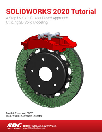
Axle Support, the Technical DrawingIn this tutorial we will make some technical drawings of the 3D model of the axle support that we createdin Tutorial 9. This tutorial is designed to continue with the files you made in Tutorial 9. If you did notfinish the previous tutorial or lost the files, ask your teacher about them.Creating a 2D drawing is not very difficult. We will show you a number of examples of single part and assembly drawings. Also, we will show you how to make an exploded view.Work planThe first part is the inner tube of the axle support. We will put three viewson the drawing sheet and an isometric view.SolidWorks for VMBO en MBOTutorial 10: Drawing of the Axle Support3
1Start SolidWorks and openthe part pipe.SLDPRT. Youcreated this file during thelast tutorial.2Click on New in the Standard Toolbar to open anew file.3Click on ‘Advanced’ in thepop-up menu.SolidWorks for VMBO en MBOTutorial 10: Drawing of the Axle Support4
4Select the file ‘sw-tutorial’to be your template andclick on OK.If this file does not exist,ask your teacher for it. Inthis file we have made anumber of standard settings, so you can startbuilding a proper technicaldrawing.If you are working athome, you can simplydownload the file swtutorial.DRWDOT and put itin the folder: C:\ProgramFiles\SolidWorks\data\templates.5The menu shown on theright might appear.If the menu appears, clickon OK. We will get back tothis later.6An empty drawing sheetwill appear. If the command ‘Model View’ doesnot start automatically,click on ‘Model View’ in theCommandManager.SolidWorks for VMBO en MBOTutorial 10: Drawing of the Axle Support5
789Set the first view now:1.Click on‘Pipe’.the2.Click on Next.partMake sure the settings inthePropertyManagermatch the ones on theright.1.Select Front for thefirst view.2.Put it somewhere onthe sheet.After you have positionedthe first view, the ‘Projected View’ command willstart automatically.Move your cursor aroundthe front view that you putin first. Click three times toset the three views asshown.Click on OK.If the ‘Projected View’command does not autostart, click on ‘Drawings’ inthe CommandManager andafter that on ‘ProjectedView’.Tip!There is another method for placing views in a drawing. You can use theTask Pane command. You have done this before in Tutorial 6 (Step 41). Asalways in SolidWorks: use the method that you prefer!SolidWorks for VMBO en MBOTutorial 10: Drawing of the Axle Support6
10To change the main settings of the drawing, rightclick at a random point onthe drawing sheet (not ona view). Then, select‘Properties ’.11Make sure to check the following settings:1. ‘Name’‘Pipe’.thedrawing:2. Select a ‘Scale’ of ‘1:2’.3. Paper size is ‘a3swtutorial’. When thisfile is not available, askyour teacher for it.4. Select ‘Third Angle’ (orAmericanProjection,mostly used in theNetherlands) or ‘FirstAngle’ (European Projection, mostly used inBelgium) at ‘Type ofprojection’.5. Click on OK.SolidWorks for VMBO en MBOTutorial 10: Drawing of the Axle Support7
12The views intersect now.To change their positions,drag (click and hold yourmouse button and moveyour mouse) the dottedframe that is visible aroundthe view by moving yourcursor over it.13Position the viewsshown on the right.14Click on ‘Annotate’ in theCommandManager,andthen on ‘Model Items’.asSolidWorks for VMBO en MBOTutorial 10: Drawing of the Axle Support8
15Set the following featuresin the PropertyManager:1. Select the option ‘Entiremodel’at‘Source/Destination’.2. Check the option ‘Import items into allviews’.3. Select the first option:Marked for drawingunder ‘Dimensions’.4. Check the option ‘Eliminate duplicates’.5. Click on OK.16The dimensions will nowbe displayed in the drawing.Tip!While modeling a part you will set a number of dimensions. You do this insketches and in features. What we did just now, is nothing more or lessthan copying these dimensions onto the drawing. So SolidWorks did notcome up with something by itself.When you do a sloppy job while modeling, it will show up in the dimensionson the drawing. Luckily, you can remove or change the dimensions manually and you can also add them to the drawing. In the following few steps,we will show you how.SolidWorks for VMBO en MBOTutorial 10: Drawing of the Axle Support9
17We will show the invisiblelines (dotted lines) in thedrawing now.1. Click on the side view.2. Select the second option Hidden lines visibleunder‘DisplayStyle’ in the PropertyManager.3. Click on OK.18Do the same for the frontview.19Next, we want to put anumber of dimensions inone of the other views. Forexample: the dimensionbetween the holes in thetube (35mm) is now in theright-side view but wewould rather show it in thefront view.1. Drag the size from theright-side view holdingthe Shift key.2. Releasethesizesomewhere in the frontview.3. Then,releasethe Shift key on yourkeyboard.SolidWorks for VMBO en MBOTutorial 10: Drawing of the Axle Support10
20Next, drag the size to theright position.Make sure the size isaligned with the size ‘52’which is above it. Whiledragging you can see (yellow) auxiliary lines that indicate if the sizes are actually aligned.21To shift the arrows on bothsides of the auxiliary lines,do the following:1. First, select the size byclicking on it.2. Click on the round dotyou see besides the arrow.The arrows will now moveto the inside of the line.SolidWorks for VMBO en MBOTutorial 10: Drawing of the Axle Support11
22Move a few more dimensions like you did in Step19:The tube diameter (Ø6)and the thickness of thematerial (3) are moved tothe top view.The drawing must look likethe illustration on the right.23The size Ø5 can be removed.1. Click on the size.2. Push the Del deletekey on the keyboard.SolidWorks for VMBO en MBOTutorial 10: Drawing of the Axle Support12
24We want to change thesize Ø6 to M6, because it isa screw thread.1. Select the size in thedrawing.2. Replacethetext‘ MOD-DIAM ’withthe capital ‘M’ under‘Dimension Text’ in thePropertyManager. Thefield text will read:‘M DIM ’.3. Click on OK.25Finally, we add a centerlineto the right-side view.1. Select the tube with aclick.2. Click on ‘Centerline’.Try to click on anotherview as well and push the Esc key to end the Centerline command.SolidWorks for VMBO en MBOTutorial 10: Drawing of the Axle Support13
26The drawing is now finished. You have to fill inyour name in the right bottom corner, in the titleblock.1. Right-click at a randomposition on the sheet(not on a view or a dimension).2. Click on ‘Edit SheetFormat’ in the menu.The drawing will disappeartemporarily.27Zoom in on the right bottom corner.Double-click on the textfield ‘Name’ and fill in yourown name.Do the same with class.The other text fields – suchas Date, Description andFile – will be filled in automatically by SolidWorks.28Right-click somewhere onthe page and select ‘EditSheet’ again.SolidWorks for VMBO en MBOTutorial 10: Drawing of the Axle Support14
29SavethefileAxle stand.SLDDRW.30Print the drawing.as:You can find the most important settings for theprinter commands in Tutorial 6.Ask your teacher for theright settings for the printer.Work planNext we will make a drawing of the support block. In this drawing we willlearn how to work with cross-cuts. You will also see how to change dimensions in a drawing.SolidWorks for VMBO en MBOTutorial 10: Drawing of the Axle Support15
31Add a new sheet to the filefirst:1. Right-click on the tabat the bottom of thescreen.2. Select ‘Add Sheet’ inthe pop-up menu.You have two tab sheetsnow; you can toggle between the drawings if youwant to.32Right-click somewhere onthe new drawing sheet andselect ‘Properties ’.Name the sheet: ‘Support’.Make sure the settingsmatch those of the firstsheet (Step 10).33Click on ‘View Layout’ intheCommandManager,and then on ‘Model View’.SolidWorks for VMBO en MBOTutorial 10: Drawing of the Axle Support16
34When the part ‘Support’ isopened, select it in the listin the PropertyManager. Ifnot, click on ‘Browse ’ andfind the file on your harddisk or on your memorystick.35Click on the sheet to placethe front view.36The command ‘ProjectedView’ will start automatically now. Also set the topview and the isometricview of the support block.SolidWorks for VMBO en MBOTutorial 10: Drawing of the Axle Support17
37Let’s make a cross-cut!1. Click on ‘Section View’in the CommandManager.Draw a cross-cut line. Becareful. Do this very accurately!2. Set the cursor on topof the midpoint of theupper horizontal line,but do NOT click!38Move the cursor upward;you can see a blue dottedline.Click above the view.39Move the cursor downwardnow and click underneaththe view.40Next, the cross-cut will appear and you can place itbeside the view.Tip!When you accidentally shift the cross-cut line, colored shading will appearSolidWorks for VMBO en MBOTutorial 10: Drawing of the Axle Support18
in the cross-cut drawing. This indicates that the model has to be updated.In such a case, click on the Rebuild button in the standard toolbar. The colored hatching will disappear.41To get a better view of thecountersink hole, we willopen a part of the frontview.Click on ‘Sketch’ and afterthat on Circle in the CommandManager.Set the circle just aboutthe same as in the illustration on the right.421.Make sure the circle isselected(itturnsgreen).2.Click on ‘View Layout’in the CommandManager.3.Click onSection’.‘Broken-outSolidWorks for VMBO en MBOTutorial 10: Drawing of the Axle Support19
431. Check the option ‘Preview’ in the PropertyManager.2. Click on the edge ofthe hole in the topview. The cross-cut willrun through here.3. If the preview looksgood, click on OK.44To put a centerline in thehole use the followingsteps:1. Select the first edgefrom the hole.2. Hold the Ctrl keyand select the secondedge from the hole.3. Click on the tab ‘Annotate’ in the CommandManager.4. Click on ‘Centerline’.The centerline is a bit shortnow, but you can drag theend to extend it.SolidWorks for VMBO en MBOTutorial 10: Drawing of the Axle Support20
45Add the other centerlinestoo, so the drawing will endup looking like the illustration on the right.46Set the dimensions in thedrawing now.Click on ‘Annotate’ in theCommandManagerandthen on ‘Model Items’.Use the same setting as inthe last drawing (Step 14).Make sure that the optionHole Wizard Profiles is alsochecked.Click on OK.SolidWorks for VMBO en MBOTutorial 10: Drawing of the Axle Support21
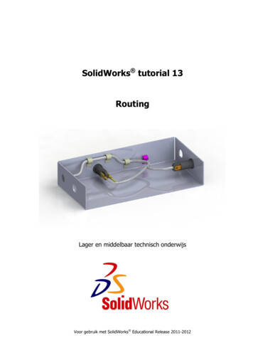
47Shift the dimensions wherenecessary so your drawinglooks orderly.Select the three dimensionsas shown on the right.Push the Del delete keyon the keyboard to removethem.48Next, set two new dimensions. Click on ‘Smart Dimension’ in the CommandManager and set the dimensions of ‘60’ and ‘100’like in the illustration.You have also used ‘SmartDimension’ in sketches soyou should be familiar withthis command.SolidWorks for VMBO en MBOTutorial 10: Drawing of the Axle Support22
49Replace the size R20 withR40 in the same way.Follow the next few stepsto set a Ø symbol in frontof the actual size:1. Select the dimension.2. Set the cursor at ‘Dimension Text’ in frontof the existing text‘ DIM ’ in the PropertyManager.3. Click on the diametersymbol. In the textfield it reads: ‘ MODDIAM DIM ’.4. Click on OK.50At some point you will seethe auxiliary lines from thedimensionsrunningthrough the view. You caneasily drag the endpoint ofthe lines to the outside ofthe view or cross-cut.Tip!Notice that we have inserted dimensions in the drawing in two differentways:1. By importing them from the 3D model.2. By putting them in the drawing manually with the Smart Dimensioncommand.There is an important difference between the two kinds of dimensions.When you double-click on an imported size, you will get a small menu inwhich you can change it. When you do so, the 3D model will also change!So be careful with this function. They are also called Driving Dimensions.It is not possible to change a manually placed dimension. If you doubleclick on those, nothing happens. These are Driven Dimensions.SolidWorks for VMBO en MBOTutorial 10: Drawing of the Axle Support23
51Fill in the right bottom corner of the drawing as youhave done before (in Steps26 to 28).Click on Save to save thefile.Work planFinally, we will make the drawing of the assembly. For this we use one ofthe views and an exploded view. To put an exploded view in the drawing,we have to make it in the assembly first.SolidWorks for VMBO en MBOTutorial 10: Drawing of the Axle Support24
52OpentheAxle stand.SLDASM.fileClick on ‘Exploded View’ inthe CommandManager.53Click on the pin.At the pin three arrows appear and you can now dragthis part in three differentdirections.54Drag the part using theblue arrow, so the pin willend up beside the assembly.Click somewhere beside themodel to un-select the pin.SolidWorks for VMBO en MBOTutorial 10: Drawing of the Axle Support25
55Drag a frame around thetop of the support to selectall parts of it.Drag from the right to theleft, so the tube will be selected as well!56Next, drag all selecteditems upward using thevertical arrow. Make surethe inner tube will extendabove the base tube.SolidWorks for VMBO en MBOTutorial 10: Drawing of the Axle Support26
57Drag the two little screwsjust below the supportblock one by one until theyare just outside of themodel.You can easily rotate themodel during this operation, but remember to putit back into the trimetricposition. This is the onlyway to you will get a clearidea about how the drawing will look like at the end.58Drag a new frame aroundthe top, but drag it fromleft to right this time. Thetube is not selected now.Make sure the supportblock is completely in theselection frame, includingthe ‘invisible’ part that isinside the tube.59Drag the selected partsupward again.SolidWorks for VMBO en MBOTutorial 10: Drawing of the Axle Support27
Tip!If the part is not directly in the right spot, you can always click on it asecond time and drag it to a new position. However, this will create a new‘Explode Step’ and make your model more complex.It is much better to find the step you want to change in the PropertyManager and then click on it. A blue arrow will appear on the part, and youcan change its position by dragging the blue arrow.60Rotate the model a little soyou can see two of thescrews in the bottom of thesupport block.Select the two screws.SolidWorks for VMBO en MBOTutorial 10: Drawing of the Axle Support28
61In order to be able to shiftthe screws in the right direction (at the same angleas the screw holes) followthe next few steps:1. Click on the field Explode Direction in thePropertyManager.2. Click on a plane fromthe screw.The arrows now change direction, and you can shiftthe screws in the right direction.62Move the other two screwsin the same way.Raise the insert.The parts are all in theright position now.Click on OK in the PropertyManager.SolidWorks for VMBO en MBOTutorial 10: Drawing of the Axle Support29
63To get a better idea abouthow the parts of the product fit together, the partsare often connected withlines.Click on ‘Explode LineSketch’ in the CommandManager to do so.64Select the two planes asshown on the right.65You can see that the linefrom the screw starts at thehead of the screw and itshould start at the otherend. Is this the same inyour drawing? Click on thegray arrow at the beginningof the line. The directionwill reverse now.When the line is ok, clickon OK in the PropertyManager.SolidWorks for VMBO en MBOTutorial 10: Drawing of the Axle Support30
66Make a similar line for oneof the screws in the support block. Select the threeplanes as shown.67Draw all connection lines inthe exploded view in thesame way.SolidWorks for VMBO en MBOTutorial 10: Drawing of the Axle Support31
68The assembly has nowturned into an ExplodedView. But how do we return to the normal assembly?1. Go to the ConfigurationManager.2. Right-click‘ExplView1’.on3. Select ‘Collapse’.To return to the explodedview again, select ‘Explode’in the same menu.Try the option ‘Animate collapse/explode’. You will seethe parts moving awayfrom and toward each other.69Make sure the assembly isexploded and save the file.Return to the drawingagain that you were working in.Push the capital ‘R’ on thekeyboard.ClickAxle stand.SLDDRW.70onAdd a drawing sheet to thefile.Click on Add Sheet.SolidWorks for VMBO en MBOTutorial 10: Drawing of the Axle Support32
71721.Click on ‘View Layout’in the CommandManager.2.Select ‘Model View’.3.Selectthe‘Axle stand’.4.Click on Next.file1. Make sure the option‘Trimetric’ is checked inthe PropertyManager.2. Put the view on thedrawing sheet.73The exploded view may beenlarged a little.1. Selectview.theexploded2. Change the ‘Scale’ to‘User Defined’ in thePropertyManager.3. Set the ‘Scale’ to ‘1:4’.SolidWorks for VMBO en MBOTutorial 10: Drawing of the Axle Support33
74Next, we will put the frontview on the sheet.1. Click once more on‘Model View’ in theCommandManager.2. Selectthe‘Axle stand’.file3. Click on Next.751. Select the Front view inthe PropertyManager.2. Put the view on thedrawing sheet.Automatically, the command Projected View willstart up. Click on OK to endthis command.SolidWorks for VMBO en MBOTutorial 10: Drawing of the Axle Support34
76The front view is still exploded, but this is notmeant to be. To changethis, right-click on the Viewand select ‘Properties ’.77Uncheck the option ‘Showin exploded state’ in themenu that appears.Next, click on OK.SolidWorks for VMBO en MBOTutorial 10: Drawing of the Axle Support35
78Change the ‘Scale’ to ‘1:2’,as you have done in Step73.79We will set the part numbers to the exploded view.1. Selectview.theexploded2. Click on ‘Annotate’ inthe CommandManager.3. Click on ‘AutoBalloon’.The part numbers now appear around the explodedview.801. Click on the option ‘Left’in the PropertyManagerto set all part numbersat the left side of theexploded view.2. You can drag the numbers to put them on theright if you want to.3. Click on OK.SolidWorks for VMBO en MBOTutorial 10: Drawing of the Axle Support36
81Finally, we will add a partslist.1. Select theview first.exploded2. Click on ‘Tables’ in theCommandManager.3. Select ‘Bill of Materials’.82Click on OK in the PropertyManager.83Put the parts list on thedrawing sheet and click OKin the PropertyManager.84We must give our assemblydrawing a name now. It isstill called ‘Sheet2’ (oranother number).Right-click on the tab whichcontains the compositiondrawing.Select the option ‘Rename’in the menu.SolidWorks for VMBO en MBOTutorial 10: Drawing of the Axle Support37
85Type in another name forthe drawing, for example:‘Assembly’.86Fill in your name in theright bottom corner.87Save the drawing and printit.What are the main features you have learnedin this tutorial?In this tutorial you have made three drawings and learned the most important functions for making a drawing. You have:-Placed views onto a drawing sheet.-Set dimensions in drawings, both automatically and manually.-Made some cross-cuts, including complete and partial cross-cuts.-Made an exploded view.-Added part numbers and a parts list to a composition drawing.There are a lot more functions to use when making drawing, but the thingsyou know now will enable you to draw any products you want!SolidWorks for VMBO en MBOTutorial 10: Drawing of the Axle Support38
SolidWorks works in educationOne cannot imagine the modern technical world without 3D CAD. Whether your profession is in the mechanical, electrical, or industrial design fields, or inthe automotive industry, 3D CAD is THE tool used bydesigners and engineers today.SolidWorks is the most widely used 3D CAD designsoftware in Benelux. Thanks to its unique combination of features, its ease-of-use, its wide applicability,and its excellent support. In the software’s annualimprovements, more and more customer requestsare implemented, which leads to an annual increasein functionality, as well as optimization of functions already available in the software.EducationA great number and wide variety of educational institutions – ranging from technical vocational trainingschools to universities, including Delft en Twente,among others – have already chosen SolidWorks.Why?For a teacher or instructor, SolidWorks providesuser-friendly software that pupils and students findeasy to learn and use. SolidWorks benefits all training programs, including those designed to solveproblems as well as those designed to achieve competence. Tutorials are available for every level oftraining, beginning with a series of tutorials for technical vocational education that leads studentsthrough the software step-by-step. At higher levelsinvolving complex design and engineering, such asdouble curved planes, more advanced tutorials areavailable. All tutorials are in English and free todownload at www.solidworks.com.For a scholar or a student, learning to work with SolidWorks is fun and edifying. By using SolidWorks,design technique becomes more and more visibleand tangible, resulting in a more enjoyable and realistic way of working on an assignment. Even better,every scholar or student knows that job opportunitiesincrease with SolidWorks because they have proficiency in the most widely used 3D CAD software in theBeneluxontheirresume.Forexample:at www.cadjobs.nl you will find a great number ofavailable jobs and internships that require SolidWorks. These opportunities increase motivation tolearn how to use SolidWorks.To make the use of SolidWorks even easier, a Student Kit is available. If the school uses SolidWorks,every scholar or student can get a free download ofthe Student Kit. It is a complete version of SolidWorks, which is only allowed to be used for educatiSolidWorks for VMBO en MBOTutorial 10: Drawing of the Axle Supportonal purposes. The data you need to download theStudent Kit is available through your teacher or instructor.The choice to work with SolidWorks is an importantissue for ICT departments because they can postpone new hardware installation due to the fact thatSolidWorks carries relatively low hardware demands.The installation and management of SolidWorks on anetwork is very simple, particularly with a network licenses. And if a problem does arise, access to aqualified helpdesk will help you to get back on theright track.CertificationWhen you have sufficiently learned SolidWorks, youcan obtain certification by taking the Certified SolidWorks Associate (CSWA) exam. By passing this test,you will receive a certificate that attests to your proficiency with SolidWorks. This can be very usefulwhen applying for a job or internship. After completing this series of tutorials for VMBO and MBO, youwill know enough to take the CSWA exam.FinallySolidWorks has committed itself to serving the needsof educational institutions and schools both now andin the future. By supporting teachers, making tutorialsavailable, updating the software annually to the latestcommercial version, and by supplying the StudentKit, SolidWorks continues its commitment to servethe educational community. The choice of SolidWorks is an investment in the future of education andensures ongoing support and a strong foundation forscholars and students who want to have the best opportunities after their technical training.ContactIf you still have questions about SolidWorks, pleasecontact your local reseller.You will find more information about SolidWorks atour website: http://www.solidworks.comSolidWorks BeneluxRTC BuildingJan Ligthartstraat 11800 GH Alkmaar, NetherlandsTel: 31 (0)72 514 35501800 GH Alkmaar, NetherlandsTel: 31 (0)72 514 355039
Tutorial 10: Drawing of the Axle Support 7. 12 . The views intersect now. To change their positions, drag (click and hold your mouse button and move your mouse) the dotted frame that is visi