Transcription
COMPUTER-AIDED DESIGN OF HORIZONTAL-AXISWIND TURBINE BLADESA THESIS SUBMITTED TOTHE GRADUATE SCHOOL OF NATURAL AND APPLIED SCIENCESOFMIDDLE EAST TECHNICAL UNIVERSITYBYSERHAT DURANIN PARTIAL FULFILLMENT OF THE REQUIREMENTSFORTHE DEGREE OF MASTER OF SCIENCEINMECHANICAL ENGINEERINGJANUARY 2005
Approval of the Graduate School of Natural and Applied SciencesProf. Dr. Canan ÖZGENDirectorI certify that this thesis satisfies all the requirements as a thesis for the degree ofMaster of Science.Prof. Dr. S. Kemal İDERHead of the DepartmentThis is to certify that we have read this thesis and that in our opinion it is fullyadequate, in scope and quality, as a thesis for degree of Master of Science.Asst. Prof. Dr. Tahsin ÇETİNKAYACo-SupervisorProf. Dr. Kahraman ALBAYRAKSupervisorExamining Committee MembersProf. Dr. O. Cahit ERALP(METU, ME)Prof. Dr. Kahraman ALBAYRAK(METU, ME)Assoc. Prof. Dr. Cemil YAMALI(METU, ME)Asst. Prof. Dr. Tahsin ÇETİNKAYA (METU, ME)Prof. Dr. İ. Sinan AKMANDOR(METU, AEE)
I hereby declare that all information in this document has been obtained andpresented in accordance with academic rules and ethical conduct. I alsodeclare that, as required by these rules and conduct, I have fully cited andreferenced all material and results that are not original to this work.Name, Last name: Serhat DURANSignatureiii:
ABSTRACTCOMPUTER-AIDED DESIGN OF HORIZONTAL-AXISWIND TURBINE BLADESDuran, SerhatM.S., Department of Mechanical EngineeringSupervisor: Prof. Dr. Kahraman ALBAYRAKCo-Supervisor: Asst. Prof. Dr. Tahsin ÇETİNKAYAJanuary 2005, 124 Pages,Designing horizontal-axis wind turbine (HAWT) blades to achieve satisfactorylevels of performance starts with knowledge of the aerodynamic forces acting onthe blades. In this thesis, HAWT blade design is studied from the aspect ofaerodynamic view and the basic principles of the aerodynamic behaviors ofHAWTs are investigated.Blade-element momentum theory (BEM) known as also strip theory, which isthe current mainstay of aerodynamic design and analysis of HAWT blades, is usedfor HAWT blade design in this thesis.Firstly, blade design procedure for an optimum rotor according to BEM theoryis performed. Then designed blade shape is modified such that modified blade willbe lightly loaded regarding the highly loaded of the designed blade and powerprediction of modified blade is analyzed. When the designed blade shape ismodified, it is seen that the power extracted from the wind is reduced about 10%iv
and the length of modified blade is increased about 5% for the same requiredpower.BLADESIGN which is a user-interface computer program for HAWT bladedesign is written. It gives blade geometry parameters (chord-length and twistdistributions) and design conditions (design tip-speed ratio, design powercoefficient and rotor diameter) for the following inputs; power required from aturbine, number of blades, design wind velocity and blade profile type (airfoiltype). The program can be used by anyone who may not be intimately concernedwith the concepts of blade design procedure and the results taken from the programcan be used for further studies.Keywords: Horizontal-Axis Wind Turbine Blades, Wind energy, Aerodynamics,Airfoilv
ÖZYATAY EKSENLİ RÜZGAR TÜRBİN PALALARININBİLGİSAYAR DESTEKLİ AERODİNAMİK TASARIMIDuran, SerhatYüksek Lisans, Makine Mühendisliği BölümüTez Yöneticisi: Prof. Dr. Kahraman ALBAYRAKOrtak Tez Yöneticisi: Asst. Prof. Dr. Tahsin ÇETİNKAYAOcak 2005, 124 Sayfa,Yatay eksenli rüzgar türbin palalarının tasarımı, öncelikle palalara etkiyenaerodinamik kuvvetlerin bilinmesini gerektirir. Bu çalışmada, yatay eksenli rüzgartürbin palalarının tasarımı konusu, akışkanlar dinamiği yönünden ele alınmış veyatay eksenli rüzgar türbinlerinin aerodinamiği ile ilgili temek teorilerincelenmiştir.Bu çalışmada, yatay eksenli rüzgar türbin palalarının tasarımı için, günümüzrüzgar türbin palalarının tasarımında en sık rastlanan yöntem olan pala elemanıteorisinden faydalanılmıştır.İlk olarak optimum rotora ait bir palanın tasarımı için gerekli metotoluşturulmuştur. Daha sonra tasarımı yapılan palaya etkiyen kuvvetlerin büyükolması dikkate alınarak, palanın geometrisi; palaya etkiyen kuvvetler ltilenyenipalalarınperformansıincelenmiştir. Bu incelemede, geometrisi düzeltilen palaların performansı;vi
optimum rotor için tasarlanmış palanın performansına oranla yaklaşık %10 azaldığıgörülmüştür. Ayrıca istenilen belirli bir türbin gücü için, geometrisi düzeltilmişpalanın boyunun, optimum rotor için tasarımı yapılan palanın boyuna oranlayaklaşık %5 daha uzun olması gerektiği görülmüştür.Yatay eksenli rüzgar türbin palalarının tasarımına yönelik; kullanıcı arayüzünesahip, BLADESIGN isminde bir bilgisayar programı yazılmıştır. Program,kullanıcının girdiği; istenilen türbin gücü, pala sayısı, dizayn rüzgar hızı ve palaprofile ( airfoil tipi) girdilerine göre pala geometrisi parametreleri (veter uzunluğuve burulma açısı dağılımları) ile dizayn şartlarındaki gerekli değerleri (dizayn uçhız oranı, dizayn güç katsayısı ve rotor çapı) vermektedir. Program, pala tasarımıkonusunda detaylı bilgiye sahip olmayan kullanıcılarına, programın şmadabulunabilmesineimkanvermektedir.Anahtar Sözcükler: Yatay Eksenli Rüzgar Türbin Palaları, RüzgarEnerjisi, Aerodinamik, Pala Profilivii
To My Familyviii
ACKNOWLEDGEMENTSThe author would like to express his deepest gratitude and appreciation to hissupervisor, Prof. Dr. Kahraman Albayrak and Co-Supervisor, Asst. Prof. Dr.Tahsin Çetinkaya for their invaluable guidance and encouragement throughout thisstudy. The author especially thanks his supervisor for his patience and trust duringthe study.The author also would like to thank his colleagues and ASELSAN Inc. fortheir supports.ix
TABLE OF CONTENTSPLAGIARISM . . . . . . . . . . . . . . . . . . . . . . . . . . . . . . . . . . . . . . . . . iiiABSTRACT. . . . . . . . . . . . . . . . . . . . . . . . . . . . . . . . . . . . . . . . . . . ivÖZ. . . . . . . . . . . . . . . . . . . . . . . . . . . . . . . . . . . . . . . . . . . . . . . . . . . viDEDICATION. . . . . . . . . . . . . . . . . . . . . . . . . . . . . . . . . . . . . . . . . viiiACKNOWLEDGEMENTS. . . . . . . . . . . . . . . . . . . . . . . . . . . . . . . ixTABLE OF CONTENTS. . . . . . . . . . . . . . . . . . . . . . . . . . . . . . . . . xLIST OF FIGURES. . . . . . . . . . . . . . . . . . . . . . . . . . . . . . . . . . . . . xiiiLIST OF TABLES. . . . . . . . . . . . . . . . . . . . . . . . . . . . . . . . . . . . . . xviiiNOMENCLATURE. . . . . . . . . . . . . . . . . . . . . . . . . . . . . . . . . . . . xixCHAPTERS1.INTRODUCTION. . . . . . . . . . . . . . . . . . . . . . . . . . . . . . . . . . . . . 11.1 Objective and Scope of the Thesis. . . . . . . . . . . . . . . . . . . . . . 11.2 Historical Development of Windmills. . . . . . . . . . . . . . . . . . . 31.3 Technological Developments of Modern Wind Turbines. . . . 92.HORIZONTAL-AXIS WIND TURBINES. . . . . . . . . . . . . . . . . . 112.1 Introduction. . . . . . . . . . . . . . . . . . . . . . . . . . . . . . . . . . . . . . . 112.2 Horizontal-Axis Wind Turbine Concepts. . . . . . . . . . . . . . . . 112.3 Modern Horizontal-Axis Wind Turbines. . . . . . . . . . . . . . . . . 142.3.1 The rotor subsystem. . . . . . . . . . . . . . . . . . . . . . . . . . . . 172.3.2 The power-train subsystem. . . . . . . . . . . . . . . . . . . . . . 192.3.3 The nacelle structure subsystem. . . . . . . . . . . . . . . . . . 19x
2.3.4 The tower subsystem and the foundation. . . . . . . . . . . . 192.3.5 The controls. . . . . . . . . . . . . . . . . . . . . . . . . . . . . . . . . . 202.3.6 The balance of electrical subsystem. . . . . . . . . . . . . . . . 202.4 Aerodynamic Controls of HAWTs. . . . . . . . . . . . . . . . . . . . . 202.5 Performance Parameters of HAWTs. . . . . . . . . . . . . . . . . . . . 222.6 Classification of HAWTs. . . . . . . . . . . . . . . . . . . . . . . . . . . . . 232.7 Criteria in HAWT Design. . . . . . . . . . . . . . . . . . . . . . . . . .243.AERODYNAMICS OF HAWTs. . . . . . . . . . . . . . . . . . . . . . . . . . 263.1 Introduction. . . . . . . . . . . . . . . . . . . . . . . . . . . . . . . . . . . . . . . 263.2 The Actuator Disk Theory and The Betz Limit. . . . . . . . . . . . 273.3 The General Momentum Theory. . . . . . . . . . . . . . . . . . . . . . . 333.4 Blade Element Theory. . . . . . . . . . . . . . . . . . . . . . . . . . . . . . . 443.5 Blade Element-Momentum (BEM) Theory. . . . . . . . . . . . . . . 503.6 Vortex Theory. . . . . . . . . . . . . . . . . . . . . . . . . . . . . . . . . . . . . 544.HAWT BLADE DESIGN. . . . . . . . . . . . . . . . . . . . . . . . . . . . . . . 624.1 Introduction. . . . . . . . . . . . . . . . . . . . . . . . . . . . . . . . . . . . . . . 624.2 The Tip-Loss Factor. . . . . . . . . . . . . . . . . . . . . . . . . . . . . . . . 634.3 HAWT Flow States. . . . . . . . . . . . . . . . . . . . . . . . . . . . . . . . . 664.4 Airfoil Selection in HAWT Blade Design. . . . . . . . . . . . . . . . 694.5 Blade Design Procedure . . . . . . . . . . . . . . . . . . . . . . . . . . . . . .714.6 Modification of Blade Geometry. . . . . . . . . . . . . . . . . . . . . . . 804.6.1 Modification of Chord-Length Distribution. . . . . . . . . . 804.6.2 Modification of Twist Distribution. . . . . . . . . . . . . . . . 814.7 Power Prediction of Modified Blade Shape. . . . . . . . . . . . . . . 824.8 Results. . . . . . . . . . . . . . . . . . . . . . . . . . . . . . . . . . . . . . . . . . . 84xi
5. COMPUTER PROGRAM FOR BLADE DESIGN. . . . . . . . . . . 1015.1 Introduction. . . . . . . . . . . . . . . . . . . . . . . . . . . . . . . . . . . . . . . 1015.2 XFOILP4. . . . . . . . . . . . . . . . . . . . . . . . . . . . . . . . . . . . . . . . . 1025.2 BLADESIGN. . . . . . . . . . . . . . . . . . . . . . . . . . . . . . . . . . . . . 1055.3 Sample Blade Design on BLADESIGN Program . . . . . . . . . 1095.4 Comparison of Outputs . . . . . . . . . . . . . . . . . . . . . . . . . . . . . . 1166. CONCLUSION . . . . . . . . . . . . . . . . . . . . . . . . . . . . . . . . . . . . . . 118REFERENCES. . . . . . . . . . . . . . . . . . . . . . . . . . . . . . . . . . . . . . . . . 122xii
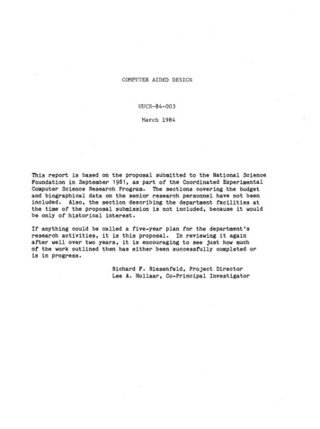
LIST OF FIGURESFIGURESFigure 1.1 Early Persian windmill. . . . . . . . . . . . . . . . . . . . . . . . . . 4Figure 1.2 The Savonius rotor. . . . . . . . . . . . . . . . . . . . . . . . . . . . . 6Figure 1.3 Darrieus rotor. . . . . . . . . . . . . . . . . . . . . . . . . . . . . . . . . 7Figure 2.1 Various concepts for horizontal-axis wind turbines. . . . 12Figure 2.2 Enfield-Andreau turbine (a) General view (b) Diagramof the flow path. . . . . . . . . . . . . . . . . . . . . . . . . . . . . . . . . . . . . . . . . 13Figure 2.3 Schematic of two common configurations: Upwind,rigid hub, three-bladed and downwind, teetered, two-bladedturbine. . . . . . . . . . . . . . . . . . . . . . . . . . . . . . . . . . . . . . . . . . . . . . . 15Figure 2.4 Major components of a horizontal-axis wind turbine. . . 16Figure 2.5 Nomenclature and subsystems of HAWT (a) Upwindrotor (b) Downwind rotor. . . . . . . . . . . . . . . . . . . . . . . . . . . . . . . .17Figure 2.6 Typical plot of rotor power coefficient vs. tip-speedratio for HAWT with a fixed blade pitch. . . . . . . . . . . . . . . . . . . .22Figure 2.7 Representative size, height and diameter of HAWTs. . . 24Figure 3.1 Idealized flow through a wind turbine represented by anon-rotating, actuator disk. . . . . . . . . . . . . . . . . . . . . . . . . . . . . . .28Figure 3.2 Velocity and pressure distribution along streamtube. . . 31Figure 3.3 Operating parameters for a Betz turbine. . . . . . . . . . . . . 33Figure 3.4 Streamtube model of flow behind rotating windturbine blade. . . . . . . . . . . . . . . . . . . . . . . . . . . . . . . . . . . . . . . . . .34Figure 3.5 Geometry of the streamtube model of flow through aHAWT rotor. . . . . . . . . . . . . . . . . . . . . . . . . . . . . . . . . . . . . . . . . .xiii35
Figure 3.6 Theoretical maximum power coefficients as a functionof tip-speed ratio for an ideal HAWT with and without wakerotation. . . . . . . . . . . . . . . . . . . . . . . . . . . . . . . . . . . . . . . . . . . . . .44Figure 3.7 Schematic of blade elements. . . . . . . . . . . . . . . . . . . . . . 45Figure 3.8 Blade geometry for analysis of a HAWT. . . . . . . . . . . . 46Figure 3.9 Tip and root vortices. . . . . . . . . . . . . . . . . . . . . . . . . . . . 55Figure 3.10 Variation of bound circulation along blade length. . . . 56Figure 3.11 Helical vortices replaced by axial and circumferentialvortex lines. . . . . . . . . . . . . . . . . . . . . . . . . . . . . . . . . . . . . . . . . . .57Figure 4.1 Relationship between axial induction factor, flow stateand thrust of a rotor. . . . . . . . . . . . . . . . . . . . . . . . . . . . . . . . . . . . . 67Figure 4.2 Variation of elemental power coefficient with relativewind angles for different values of local tip-speed ratio. . . . . . . . . 72Figure 4.3 Variation of optimum relative wind angle with respectto local tip-speed ratio at optimum elemental power coefficientfor B 3. . . . . . . . . . . . . . . . . . . . . . . . . . . . . . . . . . . . . . . . . . . . . .73Figure 4.4 Comprasion of equation 4.5.2 with the data found fordifferent glide ratios. . . . . . . . . . . . . . . . . . . . . . . . . . . . . . . . . . . .74Figure 4.5 Chord-length distribution for the designed blade. . . . .77Figure 4.6 Twist distribution for the designed blade. . . . . . . . . . . . 79Figure 4.7 Variation of power coefficient with tip-speed ratio. . . . 79Figure 4.8 Modified blade chord-length variation along the nondimensionalized blade radius. . . . . . . . . . . . . . . . . . . . . . . . . . . . .81Figure 4.9 Modified twist distribution along non-dimensionalizedblade radius. . . . . . . . . . . . . . . . . . . . . . . . . . . . . . . . . . . . . . . . . . . 82xiv
Figure 4.10 Flow chart of the iteration procedure for determiningpower coefficient of modified blade. . . . . . . . . . . . . . . . . . . . . . . . 83Figure 4.11 Effect of number of blades on peak performance ofoptimum wind turbines. . . . . . . . . . . . . . . . . . . . . . . . . . . . . . . . . . 88Figure 4.12 Effect of Drag/Lift ratio on peak performance of anoptimum three-bladed wind turbine. . . . . . . . . . . . . . . . . . . . . . . .88Figure 4.13 Effect of drag and tip losses on relative wind anglefor optimum design. . . . . . . . . . . . . . . . . . . . . . . . . . . . . . . . . . . . . 89Figure 4.14 Relative wind angle for optimum performance ofthree-bladed wind turbines. . . . . . . . . . . . . . . . . . . . . . . . . . . . . . .89Figure 4.15 Blade chord length distribution for optimumperformance of three-bladed wind turbines. . . . . . . . . . . . . . . . .90Figure 4.16 Twist angle distribution for modified chord-length ofthe designed blade. . . . . . . . . . . . . . . . . . . . . . . . . . . . . . . . . . . . . . 90Figure 4.17 Chord-length distribution of a modified blade fordifferent tip-speed ratio. . . . . . . . . . . . . . . . . . . . . . . . . . . . . . . . . . 91Figure 4.18 Twist distribution for modified twist of the designedblade. . . . . . . . . . . . . . . . . . . . . . . . . . . . . . . . . . . . . . . . . . . . . . . .91Figure 4.19 Distribution of angle of attack for modified twist ofthe designed blade. . . . . . . . . . . . . . . . . . . . . . . . . . . . . . . . . . . . . . 92Figure 4.20 Distribution of angle of attack for modified twist andchord-length of the designed blade. . . . . . . . . . . . . . . . . . . . . . . . . 92Figure 4.21 Comparison of power coefficients of modified bladeswith the designed blade. . . . . . . . . . . . . . . . . . . . . . . . . . . . . . . . .93Figure 4.22 Radial thrust coefficient variation of the designedblade . . . . . . . . . . . . . . . . . . . . . . . . . . . . . . . . . . . . . . . . . . . . . . .xv93
Figure 4.23 Radial thrust coefficient for modified twist andchord-length of the designed blade. . . . . . . . . . . . . . . . . . . . . . . . . 94Figure 4.24 Working range of the designed blade designed atλ 10 . . . . . . . . . . . . . . . . . . . . . . . . . . . . . . . . . . . . . . . . . . . . . . .94Figure 4.25 Working range of modified twist and chord-length ofthe designed blade designed at λ 10 . . . . . . . . . . . . . . . . . . . . . .95Figure 4.26 Effect of Reynolds number on peak performance ofan optimum three-bladed turbine. . . . . . . . . . . . . . . . . . . . . . . . . .95Figure 4.27 Views of blade elements from root towards tip forthe designed blade. . . . . . . . . . . . . . . . . . . . . . . . . . . . . . . . . . . . . . 96Figure 4.28 Views of blade elements from root towards tip forthe designed blade. . . . . . . . . . . . . . . . . . . . . . . . . . . . . . . . . . . . . . 96Figure 4.29 Isometric view of the blade elements for the designedblade. . . . . . . . . . . . . . . . . . . . . . . . . . . . . . . . . . . . . . . . . . . . . . . .97Figure 4.30 Isometric view of the blade elements for the designedblade. . . . . . . . . . . . . . . . . . . . . . . . . . . . . . . . . . . . . . . . . . . . . . . .97Figure 4.31 Three-dimensional solid model of the designedblade. . . . . . . . . . . . . . . . . . . . . . . . . . . . . . . . . . . . . . . . . . . . . . . .98Figure 4.32 Three-dimensional solid model of the designedblade. . . . . . . . . . . . . . . . . . . . . . . . . . . . . . . . . . . . . . . . . . . . . . . .99Figure 5.1 Comparison of XFOIL lift coefficient data with datain reference [5] . . . . . . . . . . . . . . . . . . . . . . . . . . . . . . . . . . . . . . . . 104Figure 5.2 Comparison of XFOIL drag coefficient data with datain reference [5] . . . . . . . . . . . . . . . . . . . . . . . . . . . . . . . . . . . . . . . . 104Figure 5.3 General view of BLADESIGN. . . . . . . . . . . . . . . . . . .108Figure 5.4 Flow Schematic of HAWT Blade Design program. . . . 109xvi
Figure 5.5 Comparison of power coefficient of designed andmodified blade . . . . . . . . . . . . . . . . . . . . . . . . . . . . . . . . . . . . . . . .112Figure 5.6 Comparison of setting angle variation of designed andmodified blade . . . . . . . . . . . . . . . . . . . . . . . . . . . . . . . . . . . . . . . .113Figure 5.7 Comparison of chord-length distribution of designedand modified blade . . . . . . . . . . . . . . . . . . . . . . . . . . . . . . . . . . . . . 113Figure 5.8 Three-dimensional view of the designed blade. . . . . . . 114Figure 5.9 Three-dimensional view of the modified blade. . . . . . . 114Figure 5.10 Output from the program performed for the sampleblade design case . . . . . . . . . . . . . . . . . . . . . . . . . . . . . . . . . . . . . .xvii115
LIST OF TABLESTABLESTable 1.1 Technical wind energy potential and installed capacitiesin some European countries . . . . . . . . . . . . . . . . . . . . . . . . . . . . . . 9Table 2.1 Scale classification of wind turbines. . . . . . . . . . . . . . . . 23Table 3.1 Power coefficient, C p ,max as a function of tip-speed ratioλ and a2 . . . . . . . . . . . . . . . . . . . . . . . . . . . . . . . . . . . . . . . . . . . . .43Table 4.1Blade chord and twist distribution for an optimumthree-bladed HAWT. . . . . . . . . . . . . . . . . . . . . . . . . . . . . . . . . . . .78Table 4.2 Power production of a fixed rotational three-bladedHAWT . . . . . . . . . . . . . . . . . . . . . . . . . . . . . . . . . . . . . . . . . . . . . . 100Table 5.1 Design conditions output for designed and modifiedblade . . . . . . . . . . . . . . . . . . . . . . . . . . . . . . . . . . . . . . . . . . . . . . . . 110Table 5.2 Blade geometry output for designed and modifiedblade . . . . . . . . . . . . . . . . . . . . . . . . . . . . . . . . . . . . . . . . . . . . . . . . 111Table 5.3 Comparison of outputs for the airfoils. . . . . . . . . . . . . .116Table 5.4 Comparison of rotor diameters for different turbinepower outputs. . . . . . . . . . . . . . . . . . . . . . . . . . . . . . . . . . . . . . . . .xviii117
NOMENCLATURECP: power coefficient of wind turbine rotorCP ,max: maximum rotor power coefficientCT: thrust coefficient of wind turbine rotorCTr: local thrust coefficient for each annular rotor sectionP: power output from wind turbine rotorim: air mass flow rate through rotor planeU : free stream velocity of windU rel: relative wind velocityUR: uniform wind velocity at rotor planeUw: uniform wind velocity at far wakeu: axial wind velocity at rotor planev: radial wind velocity at rotor planew: angular wind velocity at rotor planew′: induced angular velocity due to bound vorticity of rotor bladesuw: axial wind velocity at far wakevw: radial wind velocity at far wakeww: angular wind velocity at far wakeA: area of wind turbine rotorR: radius of wind turbine rotorr: radial coordinate at rotor planerw: radial coordinate at far wakerh: rotor radius at hub of the bladeri: blade radius for the ith blade elementp0: pressure of undisturbed airxix
pu: upwind pressure of rotorpd: downwind pressure of rotorp′: pressure drop across rotor planepw: pressure at far wakeH0: Bernoulli’s constant between free-stream and inflowH1: Bernoulli’s constant between outflow and far wakeT: rotor thrustQ: rotor torqueFD: drag force on an annular blade elementFL: lift force on an annular blade elementL: force on an annular element tangential to the circle swept by the rotorCD: drag coefficient of an airfoilCL: lift coefficient of an airfoilCL ,design: design lift coefficient of an airfoilF: tip-loss factorFi: tip-loss factor for the ith blade elementN: number of blade elementsB: number of blades of a rotora: axial induction factor at rotor planeb: axial induction factor at far wakea′: angular induction factorλ: tip-speed ratio of rotorλd: design tip-speed ratioλr: local tip-speed ratioλr ,i: local tip-speed ratio for the ith blade elementλh: local tip-speed ratio at the huba1: corresponding axial induction factor at λr λhxx
a2: corresponding axial induction factor at λr λc: blade chord lengthci: blade chord length for the ith blade elementρ: air densityΩ: angular velocity of wind turbine rotorα: angle of attackα design: design angle of attackθ: pitch angle (blade setting angle)θi: pitch angle for the ith blade elementϕ: angle of relative wind velocity with rotor planeϕopt: optimum relative wind angleϕopt ,i: optimum relative wind angle for the ith blade elementσ: solidity ratioν: kinematic viscosity of airγ: glide ratioΓ: circulation along a blade lengthδΓ: incremental circulation along a blade lengthRe: Reynolds numberHAWT: horizontal-axis wind turbineVAWT: vertical-axis wind turbineBEM: blade element-momentum theoryTSR: tip-speed ratioxxi
CHAPTER 1INTRODUCTION1.1 OBJECTIVE AND SCOPE OF THE THESISThe objective of this study is to develop a user-interface computer program onMATLAB for HAWT blade design and power performance prediction using theBlade-Element Momentum (BEM) theory. The program is well established and canbe readily used for the purpose of designing horizontal-axis wind turbine blades. Ittakes power required from a wind turbine rotor, number of blades to be used on therotor, the average wind speed, an airfoil type which can be selected from the airfoildatabase in the program as input and gives the following as output; blade geometryparameters (twist and chord-length) for both the designed blade and modified bladeconsidering the ease of fabrication and the approximate rotor diameter to beconstructed for the specified power. The program shows the results with figures formaking the design decision more clear. It also gives the three dimensional viewsand solid models of the designed and modified blades for visualization.The scope of the thesis is restricted to horizontal-axis wind turbines within twogeneral configurations of wind turbines; namely horizontal-axis and vertical-axiswind turbines. The following sections of this chapter, however, gives anintroductory remarks about wind turbine; its origin, development in history, someinnovative types of wind turbines, the exploration of major advantages ofhorizontal-axis wind turbines over all other wind turbines, technologicaldevelopment and use of horizontal-axis wind turbines around the world.‘In Chapter 2’, the detail information on horizontal-axis wind turbines aregiven. The concepts and some innovative types of horizontal-axis wind turbines arementioned. Then today’s modern horizontal-axis wind turbines are introducedgiving the common configurations and explanations of their sub-components. Alsonomenclatures used in horizontal-axis wind turbines with their definitions are1
included. The control strategies from the aspect of aerodynamic view are examinedand major performance parameters are introduced. Finally, classification ofhorizontal-axis wind turbines and criteria in horizontal-axis wind turbine designregarding their all sub-components apart from the rotor which is the main scope ofthis thesis are given.‘In Chapter 3’, the aerodynamic behaviors of horizontal-axis wind turbines aredealt with in detail. All theories on aerodynamic of horizontal-axis wind turbinesare examined under separate subtitles for each. The assumptions made for eachtheory are emphasized and their physical meanings are explained for the purpose ofmaking the understanding of each theory easier.‘In Chapter 4’, HAWT blade design procedure is given based on the BEMtheory. Equations obtained from BEM theory in chapter 3 are modified consideringvarious corrections including tip-losses and thrust coefficient modifications. It ismentioned about the airfoil selection criteria in HAWT blade design. How airfoilcharacteristics affect the performance of a blade is discussed as well. Designprocedure is then studied for a designed blade and the validity of an approximationused for determining the optimum relative wind angle for a certain local tip-speedratio is explained and illustrated with figures. Modification of the designed bladeregarding the ease of fabrication is discussed, modification of chord-lengthdistribution of the designed blade and modification of twist distribution of thedesigned blade are studied and the performance of modified blade is analyzed andcompared with that of designed blade. At the end of this chapter results are givenwith illustrative figures. In blade design of HAWT the effect of parameters such aseffect of Reynolds number, effects of number of blades etc. are discussed and someexplanatory comment for each parameter showing on the figures are made.‘In Chapter 5’, the computer programs namely XFOIL used for airfoil analysisand the user-interface program on HAWT blade design; BLADESIGN developedon MATLAB are introduced. An example of blade design performed on thementioned program is given.2
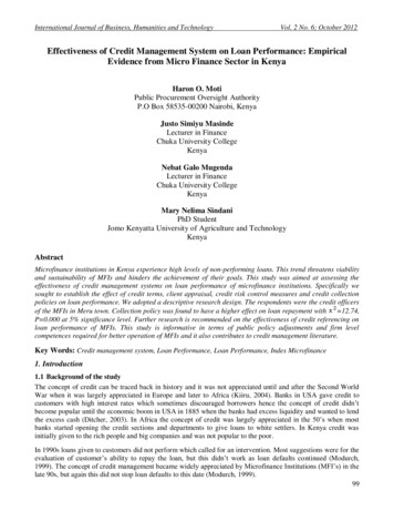
1.2 HISTORICAL DEVELOPMENT OF WINDMILLSEven though today’s modern technology has firmly and rightly established thedefinition of wind turbine as the prime mover of a wind machine capable of beingharnessed for a number of different applications, none of which are concerned withthe milling of grain or other substances (at least industrialized countries), the termwindmill was used for the whole system up to recent time, whatever its duty, be itgenerating electricity, pumping water, sawing wood. Since here the historicaldevelopment of wind machine is considered it is convenient and has certain logic init to retain its term, windmill in its historic sense [1].The windmill has had a singular history among prime movers. Its existence asa provider of useful mechanical power has been known for the last thousands years.The earliest mentions of the use of wind power come from the East India, Tibet,Persia and Afghanistan. It is also mentioned that the wind power was used to playthe organ instrument in İskenderiye about two thousands years ago. Nearly allstories and the records we have about windmill from between the first and twelfthcenturies come from the Near East and Central Asia and those regions of the worldare generally considered to be the birthplace of the windmill.The first record of the use of the windmill is seen in the tenth century inPersia. Inhabitants who lived in Eastern Persia, which bordered on Afghanistantoday, utilized the windmill, which were vertical-axis and drag type of windmill asillustrated in Figure 1.1. The invention of the vertical-axis windmills subsequentlyspread in the twelfth century throughout Islam and beyond to the Far East. Thebasic definition of the primitive vertical-axis windmills were imported in the latercenturies such as placing the sails above millstones , elevating the driver to a moreopen exposure which improved the output by exposing the rotor to higher windspeeds and using of reeds instead of cloth to provide the working surface [1].3
Figure 1.1 Early Persian windmill [2]However, it lies in the fact that the vertical-axis Persian windmills never cameinto use in Europe. At the end of the twelfth century, there was an efflorescence ofa completely different type, the horizontal-axis windmill. This development presentsecond enigma in the technical development of the wind turbine that occurred somethousands years after the enigma left by Persian vertical-axis windmills [1].Before European countries, horizontal-axis windmills were designed by Ebulİz (1153) from Artuk Turks and used in the region of Diyarbakır in 1200’s.However, Northwest Europe, particularly France, Germany, Great Britain, Iberiaand the Low Countries are considered to be the first region that developed the mosteffective type of windmill, one in which the shaft carrying the sails was orientedhorizontally rather than vertically as in the Persian mill. In a relatively short time,tens of thousands of what it is called horizontal-axis European windmills were inuse for nearly all mechanical task, in
computer-aided design of horizontal-axis wind turbine blades a thesis submitted to the graduate school of natural and applied sciences of middle east technical university by serhat duran in partial fulfillment of the requirements for the degree of