Transcription
Technical Guidefor Cold-FormedSteel Framing ProductsTechnical Data in this publication is applicableto the following SFIA Member Company:For a complete directory of SFIA Members who are certified for compliancewith the International Building Code and all appplicable ASTM and n/SFIA SteelFraming Intertek.aspxThe data in this guide is based upon the 2016 American Ironand Steel Institute’s S100-16 “North American Specification forthe Design of Cold-Formed Steel Structural Members”, the 2015American Iron and Steel Institute’s S240-15 “North AmericanSpecification for Cold-Formed Steel Structural Framing”, andmeets the requirements of the IBC 2018 Building Code, as wellas the 2016 California Building Code and 2017 Florida BuildingCode.Complies with the 2018 IBC, AISI S100-16, and AISI S240-15
IntroductionSTEEL FRAMING INDUSTRY ASSOCIATIONThe Steel Framing Industry Association (SFIA) was formed with the objective of assisting companies having interests in thecold-formed steel framing industry to be more successful by unifying the industry to expand the market for the use of coldformed steel systems through:(a) Quality Assurance(b) Promotion(c) Advocacy(d) Education(e) InnovationThe SFIA developed this Industry leading product technical guide to comply with the latest building codes and standards.The data in this catalog based on the American Iron and Steel Institure’s AISI S100-16 “North American Specification for the Design of Cold-Formed Steel Structural Members and meets the requirements of the 2018 International Building Code (IBC). Whilebuilding codes vary by jurisdiction, this program follows the most recent international standards published by the InternationalCode Council.Material SpecificationProducts manufactured by SFIA members are formed from steel with a minimum yield stress of 33 or 50 kips per square inch(ksi). Unless noted otherwise, all products covered in this SFIA catalog are engineered to meet the 2016 edition of the AmericanIron and Steel Institute (AISI) S100-16, “North American Specification of the Design of Cold-Formed Steel Structural Members”and other AISI standards referenced in Section 2210 of the 2018 International Building Code (IBC-2018). The structural properties in this SFIA catalog have been computed based on allowable stress design (ASD) which includes distortional bucklingconsiderations for all Stud Sections. For fastener tables, screw sizes and head diameters do not refer to specific fasteners whichmay or may not be available from SFIA member companies. Shear and tension data for screws was developed using publishedmanufacturer data and evaluation reports available at the time of publications.DisclaimerA concerted effort has been made to ensure the accuracy of the technical data represented in this catalog. The Steel Framing IndustryAssociation makes no representation, warranty, or guarantee in connection with this technical data and expressly disclaims any liability or responsibility for failure resulting from the use or misapplication of computations, detail drawings and specifications containedherein. All data, specifications and details contained in this catalog publications are intended as a general guide for using SFIA member companies products. These products should not be used in design or construction without an independent evaluation by a qualified engineer or architect to verify the suitability of a particular product for use in a specific application. This publication containes thelatest information available at the time of printing. The SFIA and its member companies reserve the right to make modifications and/or change materials of any of their products without prior notice or obligation. For the latest information regarding a particular manufacturer’s products contact that manufacturer. All SFIA manufacturers may not produce all of the products listed in this catalog. Pleasecontact manufacturer to verify product availablity.Copyright 2018 Steel Framing Industry Association
Table of ContentsSTEEL FRAMING INDUSTRY ASSOCIATIONINTRODUCTION . . . . . . . . . . . . . . . . . . . . . . . . . . Inside Front CoverFloor Joist Span Tables . . . . . . . . . . . . . . . . . . . . . . . . . . . . . . . . . . . 58Material Specifications . . . . . . . . . . . . . . . . . . . . . . . Inside Front CoverAllowable Floor Joist Span Table Notes . . . . . . . . . . . . . . . . . . . . . . 58Disclaimer . . . . . . . . . . . . . . . . . . . . . . . . . . . . . . . . . . . Inside Front CoverAllowable Floor Joist Spans . . . . . . . . . . . . . . . . . . . . . . . . . . . . . . . . . 59Table of Contents . . . . . . . . . . . . . . . . . . . . . . . . . . . . . . . . . . . . . . . . 1Header Load Tables . . . . . . . . . . . . . . . . . . . . . . . . . . . . . . . . . . . . . . 72Header Load Table Notes . . . . . . . . . . . . . . . . . . . . . . . . . . . . . . . . . . . 72General Product Information . . . . . . . . . . . . . . . . . . . . . . . . . . . . . 2Product Identification. . . . . . . . . . . . . . . . . . . . . . . . . . . . . . . . . . . . . . . . .2Header Allowable Uniform Loads . . . . . . . . . . . . . . . . . . . . . . . . . . . 73Thickness – Steel Components . . . . . . . . . . . . . . . . . . . . . . . . . . . . . . . .3Web Crippling Load Tables . . . . . . . . . . . . . . . . . . . . . . . . . . . . . . . 77Design Stiffening Lip Length . . . . . . . . . . . . . . . . . . . . . . . . . . . . . . . . . .3Web Crippling Load Table Notes . . . . . . . . . . . . . . . . . . . . . . . . . . . . 77General Notes for all Tables . . . . . . . . . . . . . . . . . . . . . . . . . . . . . . . . . . .3Web Crippling Conditions. . . . . . . . . . . . . . . . . . . . . . . . . . . . . . . . . . . 77Definitions of Structural Property Symbols . . . . . . . . . . . . . . . . . . . .4Allowable Web Crippling Loads – Single Members . . . . . . . . . . . 78Allowable Web Crippling Loads – Back-to-Back Members . . . . 80Section Properties . . . . . . . . . . . . . . . . . . . . . . . . . . . . . . . . . . . . . . . . 5Section Properties Table Notes . . . . . . . . . . . . . . . . . . . . . . . . . . . . . . . .5Channel Properties . . . . . . . . . . . . . . . . . . . . . . . . . . . . . . . . . . . . . . 82Non-Structural (S) Stud Section Properties . . . . . . . . . . . . . . . . . . . . .6U-Channel Section Properties . . . . . . . . . . . . . . . . . . . . . . . . . . . . . . . 82Structural (S) Stud Section Properties. . . . . . . . . . . . . . . . . . . . . . . . . .7U-Channel Allowable Ceiling Spans . . . . . . . . . . . . . . . . . . . . . . . . . 82Structural (T) Track Section Properties . . . . . . . . . . . . . . . . . . . . . . . 11(Hat) Furring (F) Channel Section Properties . . . . . . . . . . . . . . . . . 83Web Depth to Thickness Ratios . . . . . . . . . . . . . . . . . . . . . . . . . . . . . . 16(Hat) Furring (F) Channel Allowable Ceiling Spans. . . . . . . . . . . . 83Wall Height Tables . . . . . . . . . . . . . . . . . . . . . . . . . . . . . . . . . . . . . . . 17Fasteners (Screws and Welds). . . . . . . . . . . . . . . . . . . . . . . . . . . . . 85Interior Non-Structural Non-Composite . . . . . . . . . . . . . . . . . . . . . 17Allowable Loads for Screw Connections . . . . . . . . . . . . . . . . . . . . . 85Interior Non-Structural Composite . . . . . . . . . . . . . . . . . . . . . . . . . . 20Allowable Loads for Fillet Welds and Flare Groove Welds. . . . . . 86Limiting Wall Heights –Curtain Wall Single-Span Table Notes . . . . . . . . . . . . . . . . . . . . . . . . 22Typical Details. . . . . . . . . . . . . . . . . . . . . . . . . . . . . . . . . . . . . . . . . . . 87Limiting Wall Heights – Curtain Wall Single-Span . . . . . . . . . . . . 23Joist Bridging . . . . . . . . . . . . . . . . . . . . . . . . . . . . . . . . . . . . . . . . . . . . . . . 87Strapping Lateral Bracing . . . . . . . . . . . . . . . . . . . . . . . . . . . . . . . . . . . 88Combined Axial and Lateral Load Tables . . . . . . . . . . . . . . . . . . 33Combined Axial and Lateral Load Table Notes . . . . . . . . . . . . . . . 33Additional Technical Resources . . . . . . . . . . . . . . . . . . . . . . . . . . . 89Allowable Axial Loads. . . . . . . . . . . . . . . . . . . . . . . . . . . . . . . . . . . . . . . 34Fire Rated Assemblies and Generic CFS Products . . . . . . . . . . 90SFIA Information . . . . . . . . . . . . . . . . . . . . . . . . . . . . . . . . Back CoverComplies with the 2018 International Building Code and AISI S1001
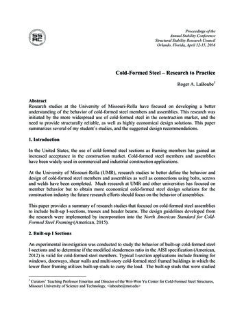
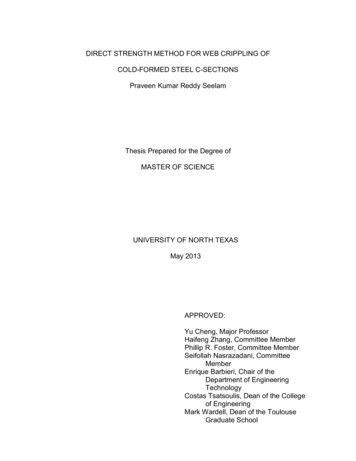
General Product InformationSTEEL FRAMING INDUSTRY ASSOCIATIONThe Steel Framing Industry Association (SFIA) supports the industry standard nomenclature published in the American Ironand Steel Institures’s (AISI) General Provisions, S200, The AISI S200 states in Section A5.2 that .”structural members and nonstructural members shall use a four-part product designator that identifies the size (both web depth and flange width), style, andthickness.” An example of this designator is shown below:EXAMPLE:MEMBER DEPTH:(Example: 3-5/8" 3.625" 362 x 1/100 inches)All member depths are taken in 1/100 inches.For all “T” Sections, member depth is theinside to inside dimension.FLANGE WIDTH:(Example: 1-5/8" 1.625” 162 x 1/100 inches)All flange widths are taken in 1/100 inches.STYLE:(Example: Stud or Joist section S)The five alpha characters utilized by the designator system are:S Stud or Joist SectionsT Track SectionsU Channel SectionsF Furring Channel SectionsL Angle or L-headerMATERIAL THICKNESS:(Example: 0.054 in 54 mils; 1 mil 1/1000 in.)Material thickness is the minimum base metalthickness in mils. Minimum base metal thickness represents 95% of the design thickness.NOTE: For Structural members 54 mil (16 gauge) and thicker, that have both 33 and 50 ksi yield strengthoptions shown, the designer shall identify which yield strength he has specified and the manufacturer shalllabel the product with the yield strength.2Complies with the 2018 International Building Code and AISI S100
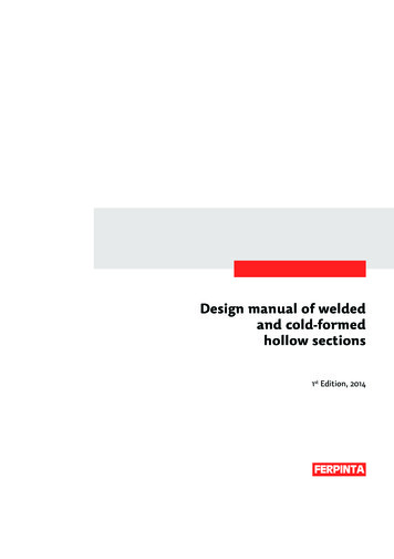
General Product InformationThickness TableSTEEL FRAMING INDUSTRY ASSOCIATIONStiffening Lip in)DesignThickness(in)DesignInside CornerRadii2 (in)ReferenceGaugeNo.SectionFlange WidthDesign StiffeningLip Length (in)180.01790.01880.084425S1251 1/4"0.1881 3/8"0.3751 alS2002"0.6252 .084916S3003"0.625680.06770.07130.107014S3503 63101Minimum Thickness represents 95% of the design thickness and is the minimum acceptable thickness delivered to the jobsitebased on section A2.4 of the AISI S100-16.2The tables in this catalog are calculated based on inside corner radii listed in this table.General Notes for all Tables1.Where AISI S100-16 is referenced, it is the “North American Specification for the Design of Cold-Formed Steel StructuralMembers”, 2016 Edition, with US provisions.2.The strength increase from cold work of forming has been incorporated for flexural strength per Section A7.2 of AISI S10016.3.The effective moment of inertia for deflection is calculated at a stress which results in a section modulus such that thestress times the section modulus at that stress is equal to the allowable moment. AISI S100-16 Specification Procedure 1for serviceability determination has been used. Increases in the effective moment of Inertia (Ixe) may be possible at lowerstress levels. Any modified values would be required to be calculated by a qualified engineer.4.Various sections may be manufactured with yield points of 33 or 50 ksi. The yield point used for calculations are listed in thetables.5.For sections available in both 33 and 50 ksi, the specifier must be clearly indicate which yield point is required. For example:362S162-68 (50ksi).6.When provided, factory punchouts will be located along the centerline of the webs of the members and will have aminimum center-to-center spacing of 24 inches. Punchouts for members greater that 2.5 inches deep are a maximum of 1.5inches wide x 4 inches long.Members with depths 2.5 inches and smaller are maximum of 3/4 inches wide x 4 inches long.Complies with the 2018 International Building Code and AISI S1003
General Product InformationDefinitions of Structural Property SymbolsGross PropertiesIx:Moment of inertia of gross section about the X-X axis (strong axis).Sx:Section modulus about the X-X axis (strong axis).Rx:Radius of gyration of the gross section about the X-X axis.Iy:Moment of inertia of gross section about the Y-Y axis (weak axis).Ry:Radius of gyration of the gross section about the Y-Y axis.Effective PropertiesIxe:Effective moment of inertia about the X-axis.Sxe:Effective section modulus about the X-X axis (strong axis) stress Fy.Ma:Allowable Bending Moment - Based on the effective section modulus and the allowable stressincluding the strength increase from the cold-work of forming (Section A3.3.2) where applicable.Mad:Allowable Bending Moment - Based on Distortional Bucking Strength calculatedper Sections F4, F4.1 of AISI S100-16.Vag:Allowable strong axis shear away from punchout, calculated in accordance with Section G2 ofAISI S100-16.Vanet: Allowable strong axis shear at punchout, calculated in accordance with Section G3 of AISI S100-16.Torsional and Other PropertiesJ:St. Venant Torsional Constant.Cw:Torsional warping constant.m:Distance from shear center to mid-plane of web.Xo:Distance from the shear center to the centroid along the principal X-axis.Ro:Polar radius of gyration about the centroidal principal axis.b:1-(Xo/Ro)2Lu:The longest weak axis (Ly) and torsional (Lt) unbraced length at which lateral torsional buckling isrestrained in accordance with Section F2.1 of AISI S100-16.4Complies with the 2018 International Building Code and AISI S100
Section PropertiesSection Properties Table Notes1. Calculated properties are based on AISI S100-126 “North American Specification for the Design of Cold-Formed Steel Structural Members.”2. The centerline bend radius is based upon inside corner radii shown in Table as shown in the Thickness Table (page 3).3. Effective properties incorporate the strength increase from the cold work of forming as applicable per AISI A3.3.2.4. Tabulated gross properties, including torsional properties, are based upon full-unreduced cross section of the studs, away from punchouts.5. For deflection calculations, use the effective moment of inertia.6. Allowable moment includes cold-work of forming.7. For the steels that have both 33 and 50 ksi listing, if the design is based upon 50 ksi, the 50 ksi steel needs to be specified. (Example: 3625 S137 16-50 (50 ksi)).8. Web depth for track sections is equal to the nominal stud width plus 2 times the design thickness plus the bend radius. Hems on nonstructural track sectionsare ignored.Complies with the 2018 International Building Code and AISI S1005
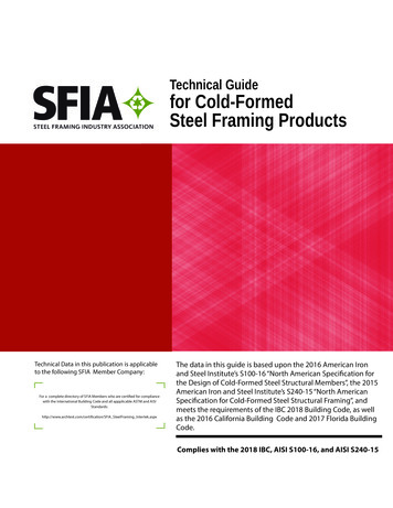
Section PropertiesSTEEL FRAMING INDUSTRY ASSOCIATIONNon-Structural (S) Stud Section 96Gross PropertiesSxRxIy(in3)(in)(in4)0.046 0.686 0.0160.069 0.682 0.0230.075 0.681 0.0260.083 0.679 0.0280.079 1.014 0.0190.118 1.009 0.0270.129 1.008 0.0300.142 1.007 0.0330.182 1.002 0.0410.222 0.994 0.0490.123 1.366 0.0210.183 1.361 0.0300.201 1.360 0.0330.222 1.358 0.0360.284 1.352 0.0460.348 1.344 0.0550.129 1.409 0.0210.192 1.404 0.0310.210 1.402 0.0330.232 1.401 0.0370.298 1.395 0.0460.365 1.386 0.0550.147 1.536 0.0210.219 1.531 0.0310.240 1.529 0.0340.265 1.527 0.0380.341 1.522 0.0480.418 1.512 0.0570.229 2.029 0.0230.341 2.023 0.0340.375 2.022 0.0370.415 2.020 0.0410.534 2.013 0.0520.657 2.003 0.0620.260 2.190 0.0240.387 2.184 0.0350.425 2.182 0.0380.470 2.180 0.0420.606 2.173 0.0530.746 2.162 0.0630.721 2.807 0.0440.931 2.799 0.0561.149 2.787 0.7280.5080.7731.035Effective PropertiesMaMad(in-k) 4.556.635.339.897.9912.79 8 12.2910.037.5715.28 11.5820.46 1J x ional PropertiesXom(in)(in)-1.029 0.594-1.018 0.587-1.014 0.585-1.010 0.583-0.904 0.543-0.893 0.537-0.890 0.535-0.886 0.532-0.874 0.526-0.859 0.518-0.798 0.495-0.788 0.489-0.784 0.488-0.781 0.485-0.769 0.479-0.755 0.472-0.786 0.490-0.776 0.484-0.773 0.482-0.770 0.480-0.758 0.474-0.744 0.466-0.755 0.475-0.745 0.469-0.742 0.467-0.738 0.465-0.727 0.459-0.713 0.452-0.651 0.423-0.642 0.417-0.639 0.416-0.636 0.414-0.626 0.408-0.613 0.401-0.623 0.408-0.614 0.403-0.611 0.401-0.608 0.399-0.598 0.393-0.586 0.386-0.519 0.350-0.510 0.344-0.500 0.3381Web-height to thickness ratio exceeds 200. Web Stiffeners are required at all support points and concentrated loads.2When web height-to thickness ratio exceeds 260, or flange width-to-thickness rato exceeds 60, effective properties are not calculated (limitations in AISI Section .627.327.126.626.426.0See Section Properties Table Notes on page 5.6Complies with the 2018 International Building Code and AISI S100
Section PropertiesSTEEL FRAMING INDUSTRY ASSOCIATIONStructural (S) Stud Section 33335050333333505050333333505050Gross 2350.2870.2870.3490.463Effective .69VagVanetJ x l 340.5340.5360.5411Web-height-to-thickness ratio exceeds 200. Web Stiffeners are required at all support points and concentric loads. Suitability of web holes must be evaluated independently.2When web height-to thickness ratio exceeds 260, or flange width-to-thickness ratio exceeds 60, effective properties are not calculated (limitations in AISI Section 53.153.053.042.942.943.1See Section Properties Table Notes on page 5.Complies with the 2018 International Building Code and AISI S1007
Section PropertiesSTEEL FRAMING INDUSTRY ASSOCIATIONStructural (S) Stud Section 17
as the 2016 California Building Code and 2017 Florida Building Code. Complies with the 2018 IBC, AISI S100-16, and AISI S240-15 Technical Data in this publication is applicable to the following SFIA Member Company: For a complete directory of SFIA Members who are certifi ed for compliance with the Internation