Transcription
Design manual of weldedand cold-formedhollow sections1st Edition, 2014
Design manual of welded andcold-formed hollow sections1st edition, 2014Edition:FERPINTA – Indústrias de Tubos de Aço, SAinfo@ferpinta.ptwww.ferpinta.ptWith the cooperation of Luís Simões da Silva, Aldina Santiagoand Liliana Marques, Faculdade de Ciências e Tecnologia da Universidade de Coimbra.All rights reserved. No parts of this publication may be reproduced, stored in a retrieval system, or transmitted in any formor by any means, electronic, mechanical, photocopying recording or otherwise, without the prior permission of the copyrightowner.FERPINTA assumes no liability with respect to the use for anyapplication of the material and information contained in thispublication.Copyright 2014 FERPINTA – Indústrias de Tubos de Aço, SAPrinted inLegal dep.
ivDesign manual of welded and cold-formed hollow sectionsMAIN SECTIONSTABLE OF CONTENTS0301PART A2. STRUCTURAL ANALYSIS2.1 Types of analysis and imperfections2.2 Cross section classification2.3 Reliability of the design method1. INTRODUCTION 011.1 The structural tube1.2 Scope and organization of themanual03070707100101113. RESISTANCE OF CROSS SECTIONS113.1 Compression or tension in laterally restrained members113.2 Uniaxial major axis bending113.3 Shear force 123.4 Torsion 123.5 Combined shear and bending or torsion133.6 Combined bending and axial force14
vDesign manual of welded and cold-formed hollow sectionsTABLE OF CONTENTS174. BUCKLING RESISTANCE OFMEMBERS4.1 Compression4.1.1 Elastic critical load4.1.2 Flexural buckling resistance4.2 Latteraly unrestrained beams4.2.1 Elastic critical moment4.2.2 Lateral-torsional buckling resistance4.3 Combined bending and compression1717171719192021255. LOCAL BUCKLING SECTIONS 275.1 Introduction5.2 Rectangular hollow sections5.3 Circular hollow sections29PART B6. EXAMPLES6.1 Lattice girder in square hollow section6.2 Unrestrained beam with rectangular hollow section6.3 Beam-column in rectangular hollow section and varying crosssection class along its length: class 1 to class 46.4 Column with circular hollow section6.5 Optimization of open steel cross sections by replacing withtubular sections6.6 Verification of column from frame in rectangular hollow sectionsubject to bending moment about z-z and y-y local axis and axialforce2929313234404250272728
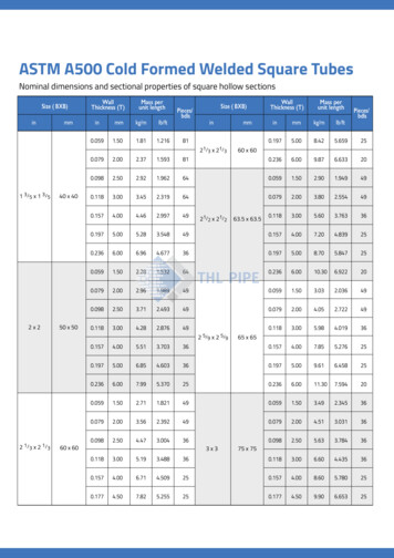
viDesign manual of welded and cold-formed hollow sectionsTABLEMAINOF CONTENTSSECTIONS57PART C577. GENERAL TECHNICAL DELIVERY CONDITIONS - EN 10219 59698. FERPINTA PROFILE TABLES698.1 Structural steel hollow sections according to EN 10219698.1.1 Circular hollow sections, Ferpinta CHS 698.1.2 Square hollow sections, Ferpinta SHS 818.1.3 Rectangular hollow sections, Ferpinta RHS 888.2 Structural steel hollow sections in high strength steel1038.2.1 Circular hollow sections, Ferpinta CHS1088.2.2 Square hollow sections, Ferpinta SHS1068.2.3 Rectangular hollow sections, Ferpinta RHS1111219. REFERENCES121
Design manual of welded and cold-formed hollow sections11.1 THE STRUCTURAL TUBE1. INTRODUTION1.1 The structural tubeThe use of steel tubes in structures is a major advantage to the steel and compositeconstruction field. It is produced in severalresistance classes. With the use of hollowsections, it is possible to obtain:i) resistant structures, with excellent resistance to compression and torsion;(ii) light and dynamic structures; and(iii) with a high ratio “Resistance/Weight”.Due to their versatility, low weight and easeof maintenance, the tubes are widely used ingreat projects allowing large spans, such as infootball stadiums, airports, sports facilitiesand oil rigs.Aesthetical appearanceThe use of circular, square and rectangulartubes contributes significantly to the improvement of the architectural componentof the structure. Structures with hollowsections have attractive, modern and innovative aesthetical appearance. It is verycommon to use these sections in spaceframes and trusses.UniformityThe intrinsic properties of hollow sectionsresult in uniform mechanical and geometrical characteristics, which, on its turn, lead topredictable and easy application. In addition,since hollow sections present smooth surfaces, do not have sharp edges and angles,maintenance and painting become simple andconsequently more economical.Easy technological transformationNot only technological operations are easier(with adequate preparation in the designphase), but also structural tube providessignificant reductions in costs. Due to thelower surface area (AL) when compared toopen sections, painting; fire protection; andmaintenance become cheaper.Resistance / ConsistencyTubular structures also offer greater fire resistance than open sections due to decreasedsurface exposed. The possibility that theseare also easily filled with concrete, mainlyin columns, gives a considerable increase inwhat concerns mechanical strength and fireresistance. These profiles have smooth surfaces and do not have corners, which promotesresistance to corrosion.Finally, due to the high warping resistance,tubular sections do not require major precautions during erection/assembly phase. Dueto this, tubular sections are usually used incranes and scaffolding structures, without theneed to major restraining solutions.Environmentally friendlySteel is one of the most recyclable materials inthe world, and unlike other construction products does not contribute to the greenhouseeffect. In combination with hollow sectionswhen applied to structural applications – temporary or not – these are much more easilydismantled allowing reuse.1.2 Scope and organization of themanualThis document aims at providing the rulesfor verification of structural hollow sectionsaccording to European Standard Eurocode 3– Part 1-1 General rules and rules for buildings (EC3-1-1) [1], pragmatically and throughkey examples.It is organized into 3 main parts:–– Part A. Safety verification of structureswith steel hollow sections;–– Part B. Numerical examples;–– Parte C. Product standards andFERPINTA hollow sections.
PART A
Design manual of welded and cold-formed hollow sections51.1PARTTHEA STRUCTURAL TUBEPART AGlobal analysis of internal forces and displacements in a structure, in particular in a steelstructure, depends mainly on its deformability and stiffness properties, as well as on the global and member stability, cross section resistance and behavior, imperfections and supportdeformability.As a result, in Part A, the following is presented:–– Chapter 2 – Structural analysis: types of analyses; member imperfections; classificationof cross sections; and safety factors;–– Chapter 3 – Resistance of cross sections;–– Chapter 4 – Stability of members;–– Chapter 5 – Local buckling of cross sections (class 4).
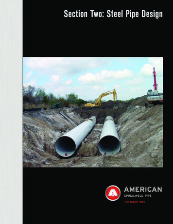
7Design manual of welded and cold-formed hollow sections2.1 TYPES OF ANALYSES AND IMPERFECTIONS2. STRUCTURAL ANALYSIS2.1 Types of analyses and imperfectionsSteel structures are usually slender structures when compared to alternatives using othermaterials. Instability phenomena are potentially present, so that it is normally necessaryto verify the global stability of the structure or of part of it. This verification leads tothe need to carry out a 2 nd order analysis, with the consideration of imperfections (EC31-1 clause 5.2.2(2)). There is a multiplicity of ways to assess 2 nd order effects includingimperfections. In general terms and according to clause 5.2.2(3), the different procedurescan be categorized according to the following three methods (EC3-1-1 clause 5.2.2(3)):–– global analysis directly accounts for all imperfections (geometrical and material) andall 2nd order effects (method 1);–– global analysis partially accounts for imperfections (global structural imperfections) and2nd order effects (global effects), while individual stability checks on members (clause 6.3)intrinsically account for member imperfections and local 2nd order effects (method 2);–– in basic cases, individual stability checks of equivalent members (clause 6.3), using appropriate buckling lengths corresponding to the global buckling mode of the structure(method 3)Figure 2.1 illustrates the described methodologies.First order analysisStabilityverification ofeach elementBuckling lengthaccording to theglobal bucklingmode of thestructureSecond order analysisCross sectioncheck in theextremes of thememberStability verificationof each elementLocal effectsP-δGlobal effectsP-ΔGlobalgeometricalimperfectiosCross sectioncheck in theextremes ofthe memberBuckling length as the reallengthApproximateor numericalmethods ofanalysis of thestructureMaterial Geometricalimperfectionsof the memberNumerical methods(nonlinear Approximateor numericalmethods ofanalysis of thestructureCross sectioncheckGeneralMethod- In-plane GMNIA- LBA- Buckling curveFig. 2.1 - Methods of Structural analysis and safety verification of steel structures2.2 Cross section classificationThe local buckling of cross sections affects their resistance and rotation capacity and must beconsidered in design. The evaluation of the influence of local buckling of a cross section onthe resistance or ductility of a steel member is complex. Consequently, a deemed-to-satisfy
8Design manual of welded and cold-formed hollow sections2. STRUCTURAL ANALYSISapproach was developed in the form of crosssection classes that greatly simplify the problem.According to clause 5.5.2(1), four classes ofcross sections are defined, depending on theirrotation capacity and ability to form rotational plastic hinges:–– Class 1 – cross sections are thosewhich can form a plastic hinge withthe rotation capacity required fromplastic analysis without reduction ofthe resistance;–– Class 2 – cross sections are those whichcan develop their plastic resistance moment, but have limited rotation capacitybecause of local buckling;–– Class 3 – cross sections are those inwhich the stress in the extreme compression fibre of the steel member,assuming an elastic distribution ofstresses, can reach the yield strength. However, local buckling is liableto prevent development of the plastic resistance moment;–– Classe 4 – cross sections are those inwhich local buckling will occur beforethe attainment of yield stress in one ormore parts of the cross section.The classification of a cross section dependson the width to thickness ratio c/t of theparts subjected to compression (EC3-1-1clause 5.5.2(3)), the applied internal forces and the steel grade. Parts subject tocompression include every part of a crosssection which is either totally or partiallyin compression under the load combination considered (EC3-1-1 clause 5.5.2(4)).The limiting values of the ratios c/t of thecompressed parts are indicated in Tables 2.1to 2.2 that reproduce Table 5.2 of EC3-1-1, inwhat concerns tubular sections.For rectangular and square hollow sections,c h - 3t or c b - 3t.Table 2.1 - Maximum width-to-thickness ratios for internal compression partsInternal compression parts or RHS or SHS cross sectionsClassPart subjectedto bendingPart subjectedto compressionPart subjected to bending andcompressionStress distribution(compression positive)1c t 72εif α 0, 5, c t 396 ε13 α 1if α 0, 5, c t 36 εαc t 33ε
9Design manual of welded and cold-formed hollow sectionsSTRESS2.2 CROSSDISTRIBUTIONSECTION CLASSIFICATIONTable 2.1 - Maximum width-to-thickness ratios for internal compression parts2if α 0, 5, c t 456 ε13 α 1if α 0, 5, c t 41, 5 εαc t 38εc t 83εStress distribution(compression positive)if Ψ 1, c t 342 ε0, 67 0, 33 Ψc t 42 εc t 124 εif Ψ 1*, c t 62 ε ( 1 Ψ )ε 235 fy( Ψ )fy (N/mm2)235275355420460ε1,000,920,810,750,71*Y -1 applies where either the compression stress σ fy or the tensile strain εy fy /E.Table 2.2 - Maximum width-to-thickness ratios for compression partsTubular sectionsdtClassSection in bending and/or compression1d / t 50 ε 22d / t 70 ε 2d / t 90 ε 23Note: For d/t 90ε2, see EN 1993-1-6 [2]
10Design manual of welded and cold-formed hollow sections2. STRUCTURAL ANALYSISTable 2.2 - Maximum width-to-thickness ratios for compression partse 235 / fyfy (N/mm2)235275355420460ε1,000,920,810,750,71As alternative to Table 2.2, a new limit d/t is proposed in [3] for classification of circular hollowsections subject to bending and axial compression, given byd t 2520ε 25ψ 23Eq. 2.12.3 Reliability of the design methodsFor steel members, the following three failure modes are considered (clause 6.1(1)): i) resistance of cross sections, whatever the class; ii) resistance of members to instability assessedby member checks and iii) resistance of cross sections in tension to fracture. The first two areaddressed in the application. Specific partial safety factors γM0, γM1 and γM2, deemed to guarantee the reliability targets of EN 1990 [5], correspond to each failure mode, respectively. Thefollowing values of the partial safety factors γMi are recommended for buildings: γM0 1.00;γM1 1.00 and γM2 1.25 are considered here.
11Design manual of welded and cold-formed hollow sections3.1 COMPRESSION OR TENSION IN LATERALLY RESTRAINED MEMBERS3. RESISTANCE OF CROSS SECTIONS3.1 Compression or tension in laterally tion, fy is the yield strength of steel and γM0 isa partial safety factor. In evaluating Nc,Rd, holesrestrained membersAccording to clause 6.2.3, the cross sectionresistance of axially tensioned members isverified by the following condition:NEd 1, 0Nt,RdEq. 3.1where NEd is the design value of the axial forceand Nc,Rd is the design resistance of the crosssection for uniform tension. According to clause6.2.4, the design value of the tension resistantaxial force Nt,Rd, in general, is given by the smallest value between the plastic design resistanceof the whole section Npl,Rd design ultimateresistance of the net cross section at holes forfasteners Nu,Rd.The cross section resistance of axially compressed members is verified by the followingcondition (EC3-1-1 clause 6.2.4(1)):for fasteners can be neglected, provided theyare filled by fasteners and are not oversize orslotted (EC3-1-1 clause 6.2.4(3)).3.2 Uniaxial Major Axis bendingIn the absence of shear forces, the design value of the bending moment MEd at each crosssection should satisfy (EC3-1-1 clause 6.2.5(1)):Eq. 3.5MEd 1, 0Mc ,Rdwhere MEd is the design value of the bendingmoment and Mc,Rd is the design resistance forbending. The design resistance for bendingabout one principal axis of a cross section isdetermined as follows (EC3-1-1 clause 6.2.5(2)):- Class 1 or 2 cross sectionsMc ,Rd Wpl fy γ M0NEd 1, 0Nc ,RdEq. 3.2Eq. 3.6- Class 3 cross sectionswhere NEd is the design value of the axial forceand Nc,Rd is the design resistance of the crosssection for uniform compression, given by(EC3-1-1 clause 6.2.4(2)):- Class 1, 2 or 3 cross sectionsMc ,Rd Wel,min fy γ M0Eq. 3.7- Class 4 cross sectionsMc ,Rd Weff ,min fy γ M0Nc ,Rd A fy γ M0Eq. 3.3Eq. 3.8- Class 4 cross sectionNc ,Rd Aeff fy γ M0Eq. 3.4where A is the gross area of the cross section,Aeff is the effective area of a class 4 cross sec-where Wpl is the plastic section bending modulus; Wel,min is the minimum elastic sectionbending modulus; Weff,min is the minimum elastic bending modulus of the reduced effectivesection; fy is the yield strength of the material;and γM0 is the partial safety factor.
12Design manual of welded and cold-formed hollow sections3. RESISTANCE OF CROSS SECTIONS3.3 Shear forceAν 2 A / πAccording to clause 6.2.6, the design value ofthe shear force, VEd, must satisfy the followingcondition:VEd 1, 0Vc ,RdEq. 3.13where A is the cross sectional area; b is theoverall breadth; and h is the overall depth.Considering elastic design, the verificationof resistance to shear force is given by thefollowing criterion:Eq. 3.9where Vc,Rd is the design shear resistance.Considering plastic design, in the absence oftorsion the design shear resistance, Vc,Rd, isgiven by the design plastic shear resistance,Vpl,Rd, given by the following expression:(Vpl,Rd Aν fy)3 γ M0fy(τ Ed3 γ M0where τEd is the design value of the local shearstress at a given point. For tubular sections itis obtained from:τ Ed - rectangular hollow sections of uniform thickness, load parallel to depth:Aν Ah / (b h)Eq. 3.11- rectangular hollow sections of uniform thickness, load parallel to width:Aν Ab / (b h) 1, 0Eq. 3.14Eq. 3.10where An is the shear area, defined in a qualitative manner for a section subjected to shear.The shear area corresponds approximatelyto the area of the parts of the cross sectionthat are parallel to the direction of the shearforce. Clause 6.2.6(3) provides expressions forthe calculation of the shear area for tubularsteel sections:)VEd S2ItEq. 3.15Where VEd is the design value of the shear force;S is the first moment of area about the centroidal axis of that portion of the cross sectionbetween the point at which the shear is requiredand the boundary of the cross section; I is thesecond moment of area about the neutral axis; tis the thickness of the section at the given point.The shear buckling resistance of webs shouldbe verified, for unstiffened webs whenhw/tw 72 ε/η, where hw and tw represent thedepth and the thickness of the web (RHS andSHS sections), respectively, η is a factor definedin EC3-1-5, which may be conservatively taken as1.0, and ε is given by the relation (235/fy). Whenload is parallel to width, hw shall be replaced bybf, where bf is the width of the hollow section.Eq. 3.123.4 Torsion- circular hollow sections and tubes of uniform thickness:The design of members subjected to atorsional moment should comply with thefollowing condition (clause 6.2.7):
13Design manual of welded and cold-formed hollow sections3.5 COMBINED SHEAR AND BENDING OR TORSIONAnd the shear stresses tt,Ed come from theuniform component Tt,Ed.TEd 1, 0TRdEq. 3.163.5 Combined shear and bending ortorsionwhere TEd is the design value of the torsionalmoment and TRd is the design torsional resistance of the cross section, evaluated accordingto the formulations presented previously.For verification of (3.44) in cross sectionsunder non-uniform torsion, the design valueof the torsional moment, TEd, should be decomposed into two components:In an elastic stress analysis, the interaction between bending and shear force may be verifiedby applying a yield criterion. This procedure,valid for any type of cross section, requires calculation of elastic normal stresses (σ) and elasticshear stresses (τ), based on formulas from thetheory of the elasticity, at the critical points ofthe cross section. The following condition (fromvon Mises criterion for a state of plane stress)has then to be verified (clause 6.2.1 (5)):TEd Tt,Ed TwEdσ von Mises σ 2 3 τ 2 Eq. 3.17fyγ M0Eq. 3.20where Tt,Ed is the internal component of uniform torsion (or St. Venant’s torsion) and Tw,Edis the internal component of warping torsion.According to clause 6.2.7 (7), for closed hollowsections, the latter may be neglected, TW,Ed 0.For the calculation of the resistance TRd of closedhollow sections the design shear strength of theindividual parts of the cross section accordingto EN 1993-1-5 should be taken into account.Finally, when shear force and torsion is presente,where Vpl,Rd shall be replaced by Vpl,T,Rd, which isthe reduced design plastic shear resistance, toaccount for the torsional moment. According toclause 6.2.7(9) the following shall be satistied:VEd 1, 0Vpl,T ,RdEq. 3.18Where, for hollow sections, Vpl,T ,Rd 1 fy Eq. 3.19τ t,Ed(3 γ M0) 1, 0 which, for the case of combined shear andbending is given by2222 σ x,Ed τ Ed My,Ed VEd 1 1fγf3γ Mel,Rd γ M0 Vel,Rd γ M0 y M0 yM0 Eq. 3.21For plastic analysis, there are several modelsfor combining shear and bending. The modelused by EC3-1-1 evaluates a reduced bendingmoment obtained from a reduced yieldstrength (fyr) along the shear area. Clause 6.2.8establishes the following interaction criterionbetween bending moment and shear force:–– When VEd 50% of the plastic shearresistance Vpl,Rd, it is not necessary toreduce the design moment resistanceMc,Rd, except where shear buckling reduces the cross section resistance.–– When VEd 50% of the plastic shear resistance Vpl,Rd, the value of the designmoment resistance should be evaluated using a reduced yield strength (1-ρ)f y for the shear area, wherer (2 VEd/Vpl,Rd-1)2.
14Design manual of welded and cold-formed hollow sections3. RESISTANCE OF CROSS SECTIONSWhen torsion is present, r (2 VEd / Vpl,T,Rd-1)2; and r 0 if VEd 0,5 Vpl,T,Rd3.6 Combined bending and axial forceIn an elastic stress analysis, the interaction between bending, axial force and shear force may beverified by applying a yield criterion. Eq. (3.13) (from von Mises criterion for a state of plane stress)has then to be verified, which, for the case of combined bending, axial force and shear is given by2222 σ x,Ed τ Ed My,Ed VEdNEd f γ f 3γ 1 N 1 el,Rd γ M0 Mel,Rd γ M0 Vel,Rd γ M0 y M0 yM0 Eq. 3.22For plastic analysis, cross section verification to combined bending and axial force is verifiedaccording in Section 6.2.9.1. For rectangular hollow sections of uniform thickness and for weldedbox sections with equal flanges and equal webs and where fastener holes are not to be accountedfor, the reduced plastic moment resistance, can also be obtained from clause 6.2.9.1(5):MN,y ,Rd Mpl,y ,Rd1 nbut MN,y ,Rd Mpl,y ,Rd1 0, 5 awMN, z ,Rd Mpl, z ,Rd1 n1 0, 5 afEq. 3.23but MN,y ,Rd Mpl,y ,RdEq. 3.24wheren NEdA 2btA 2ht 0, 5, aw 0, 5 and af 0, 5Npl,RdAAFor a circular hollow section, the following exact expression may be established (not given in EC3-1-1):(MN,Rd Mpl,Rd 1 n1,7)Eq. 3.25Finally, for bi-axial bending the following criterion may be used:αβ My ,Ed Mz ,Ed 1 MN,y ,Rd MN, z ,Rd Eq. 3.26
15Design manual of welded and cold-formed hollow sections3.6 COMBINED BENDING AND AXIAL FORCEWhere, for rectangular hollow sections,α β 1.66 61 1, 13n2Eq. 3.27And for circular hollow sections,α β 2Eq. 3.28
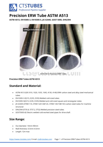
17Design manual of welded and cold-formed hollow sections4.1 COMPRESSION4. BUCKLING RESISTANCE OF MEMBERS4.1 Compression4.1.1 Elastic critical loadThe critical axial load of a straight prismaticmember is given byNcr where χ is the reduction factor for the relevant buckling mode and γM1 is a partial safetyfactor (EC3-1-1 clause 6.3.1.1(3)). The reduction factor χ is obtained from the followingexpression:π2 EILe 2χ 1φ φ2 λ 2, mas χ 1Eq. 4.5Eq. 4.1where Le k.L is the buckling length and depends on the support conditions of the column.For a simply supported column, k 1In this expression, φ 0,5 1 α ( λ 0,2 ) λ 2 and λ is the non-dimensional slendernesscoefficient, given by:4.1.2 Flexural buckling resistanceThe cross section resistance of axially compressed members is verified by the conditionin Eq. (3.2). In compression members it mustalso be verified that:- Class 1, 2 or 3 cross sectionsNEd Nb,Rdλ Afy Ncr Eq. 4.6- Class 4 cross sectionsEq. 4.2λ Aeff fy Ncr where Nb,Rd is the design buckling resistanceof the compression member (EC3-1-1 clause6.3.1.1(1)) and this generally controls design.The design flexural buckling resistance ofprismatic members is given by:- Class 1, 2 or 3 cross sectionsNb,Rd χ Afy γ M1Eq. 4.3- Class 4 cross sectionsNb,Rd χ Aeff fy γ M1Eq. 4.4λλ1λλ1AeffAEq. 4.7where Ncr is the elastic critical load (Euler’scritical load) for the relevant buckling modeand λ Le i e λ1 π E fy . The effect of imperfections is included by the imperfection factorα, which assumes values of 0.13, 0.21, 0.34,0.49 and 0.76 for curves a0, a, b, c and d (European design buckling curves), respectively.These curves, mathematically represented byequation (3.29), are illustrated in Figure 3.1.The imperfection factor α and the associatedbuckling curve to be adopted in design ofa given member depends on the geometryof the cross sections, on the steel grade, onthe fabrication process and on the relevantbuckling plane, as described in Table 3.4, forthe case of tubular sections.
18Design manual of welded and cold-formed hollow sections4. BUCKLING RESISTANCE OF MEMBERSFig. 4.1 - Buckling curves according to EC3-1-1Table 4.1 - Selection of the buckling curveBuckling curveHollowsectionsCross sectionGeometry limitsBucklingaboutaxisS 235S 275S355S420S460Cold formedanyccAccording to clause 6.3.1.2(4), for values of the non-dimensional slenderness λ 0,2 orif NEd/Ncr 0,04, the effect of buckling can be neglected, and members are designed basedonly on the cross section resistance.Annex BB.1 provides guidelines that allow quantification of the buckling length for membersin triangulated and lattice structures. In general, for the evaluation of the buckling resistanceof chord members, a buckling length equal to the real length L may be adopted, for bothin-plane and out-of-plane buckling; in some particular cases lower values can be adopted,provided that they are properly justified.Example 6.1 illustrates this procedure.
19Design manual of welded and cold-formed hollow sections4.2 LATERALLY UNRESTRAINED BEAMS4.2 Laterally unrestrained beams4.2.1 Elastic critical momentThe elastic critical moment can be estimated using expression (4.8) proposed by Clark and Hill[12] and Galéa [13], simplified for the case of tubular profiles. This is applicable to memberssubject to bending about the strong axis, for several support conditions and types of loading.2 π 2 E Iz ( kz L ) GITMcr C 1 C2 z g (kz L)2 π 2 E Iz()2 0.5 C2 z g ()Eq. 4.8where,–– C1 and C2 are coefficients depending on the shape of the bending moment diagram andon support conditions;–– kz and kw are effective length factors that depend on the support conditions at the endsections. Factor kz is related to rotations at the end sections about the weak axis z, andkw refers to warping restriction in the same cross sections. These factors vary between0.5 (restrained deformations) and 1.0 (free deformations), and are equal to 0.7 in thecase of free deformations at one end and restrained at the other. Since in most practicalsituations restraint is only partial, conservatively a value of kz kw 1.0 may be adopted;–– zg (za - zs) where za and zs are the coordinates of the point of application of the load and ofthe shear centre, relative to the centroid of the cross section; these quantities are positive iflocated in the compressed part and negative if located in the tension part;For determination of C1, the procedure from Figure 4.2 for a general bending moment distribution is considered [6]:α 1 1 k2 α 2 5A1 A2 k13k22 1k31 α 3 5 α 4 5 22k1 k1 k 2 α 5 1 k12Mmax α 1M12 α 2M22 α 3M23 α 4M24 α 5M52(1 α1)2 α 2 α 3 α 4 α 5 MmaxM 2M2 3M3 2M4 M5219Mmaxk k1 k 22C1 1 k 1 kkA1 A2 A22 2 A1Fig. 4.2 - Determination of C1 according to [6]
20Design manual of welded and cold-formed hollow sections4. BUCKLING RESISTANCE OF MEMBERSThe values of Mi and Mmax to be considered in for determination of C1 are given in Figure 4.3,with the corresponding signs.Fig. 4.3 - Values of Mi and Mmax a to be considered in the determination of C1 according to [6]The values of k1 and k2 correspond respectively to the left and right end warping and minoraxis bending conditions. If warping and bending are prevented at the left (or right) end, k1 (ork2) is 0.5; if warping and bending are free at the left (or right) end, k1 (or k2) is 1. k1 or k2 maybe safely assumed as 1 for other end conditions.Regarding C2, for a uniformly distributed loading it may be taken as C2 0.45 and C2 0.36 respectively for kz 1 and kz 0.5; and for a concentrated load at mid-span it may be taken as C2 0.59 andC2 0.48 respectively for kz 1 and kz 0.5. In beams subject to end moments, by definition, C2zg 0.4.2.2 Lateral-torsional buckling resistanceThe verification of resistance to lateral-torsional buckling of a prismatic member consists ofthe verification of the following condition (EC3-1-1 clause 6.3.2.1(1)):MEd 1, 0Mb,RdEq. 4.9where MEd is the design value of the bending moment and Mb,Rd is the design buckling resistance, given by (EC3-1-1 clause 6.3.2.1(3)):Mb,Rd χ LT Wy fy γ M1Eq. 4.10where Wy Wpl,y for class 1 and 2 cross sections; Wy Wel,y for class 3 cross sections; Wy Weff,yfor class 4 cross sections; and χLT is the reduction factor for lateral-torsional buckling.In EC3-1-1 two methods for the calculation of the reduction coefficient χLT in prismatic membersare proposed: a general method that can be applied to any type of cross section (more conservative) and an alternative method that can be applied to rolled cross sections or equivalentwelded sections. The General Method is considered here.According to the general method (clause 6.3.2.2), the reduction factor χLT is determined bythe following expression:
21Design manual of welded and cold-formed hollow sections4.3 COMBINED BENDING AND COMPRESSIONχ LT (1φLT φLT 2 λLT2)0,5, but χ LT 1,0Eq. 4.11where:φLT 0,5 1 α LT λLT 0,2 λLT2 ; aLT is the imperfection factor, which depends on the buckling0,5curve; λLT Wy fy Mcr ; Mcrthe elastic critical moment.The buckling curves to be adopted depend on the geometry of the cross section of the memberand are indicated in Table 6.4 of EC3-1-1. For tubular cross sections, curve d must me considered. Example 6.2 illustrates this procedure.()4.3 Combined bending and compressionThe instability of a member of doubly symmetric cross section, not susceptible to distortionaldeformations, and subject to bending and axial compression, can be due to flexural bucklingor to lateral torsional buckling. Therefore, clause 6.3.3(1) considers two distinct situations:–– Members not susceptible to tors
Design manual of welded and cold-formed hollow sections MAIN SECTIONS vi 57 69 121 PART C 57 7. GENERAL TECHNICAL DELI-VERY CONDITIONS - EN 10219 59 8. FERPINTA PROFILE TABLES 69 8.1 Structural steel hollow sections according to EN 10219 69 8.1.1 Circular hollow sections, Ferp