Transcription
Yu, W.W. “Cold-Formed Steel Structures”Structural Engineering HandbookEd. Chen Wai-FahBoca Raton: CRC Press LLC, 1999
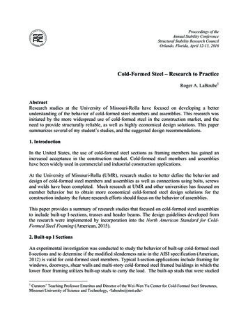
Cold-Formed Steel Structures7.17.27.37.47.57.67.77.8Wei-Wen YuDepartment of Civil Engineering,University of Missouri-Rolla,Rolla, MO7.1IntroductionDesign StandardsDesign BasesAllowable Stress Design (ASD) Limit States Design or Loadand Resistance Factor Design (LRFD)Materials and Mechanical PropertiesYield Point, Tensile Strength, and Stress-Strain Relationship Strength Increase from Cold Work of Forming Modulus ofElasticity, Tangent Modulus, and Shear Modulus DuctilityElement StrengthMaximum Flat-Width-to-Thickness Ratios Stiffened Elements under Uniform Compression Stiffened Elements withStress Gradient Unstiffened Elements under Uniform Compression Uniformly Compressed Elements with an Edge Stiffener Uniformly Compressed Elements with IntermediateStiffenersMember DesignSectional Properties Linear Method for Computing SectionalProperties Tension Members Flexural Members Concentrically Loaded Compression Members Combined Axial Loadand Bending Cylindrical Tubular MembersConnections and JointsWelded Connections Bolted Connections Screw ConnectionsStructural Systems and AssembliesMetal Buildings Shear Diaphragms Shell Roof Structures Wall Stud Assemblies Residential Construction CompositeConstruction7.9 Defining TermsReferencesFurther ReadingIntroductionCold-formed steel members as shown in Figure 7.1 are widely used in building construction, bridgeconstruction, storage racks, highway products, drainage facilities, grain bins, transmission towers,car bodies, railway coaches, and various types of equipment. These sections are cold-formed fromcarbon or low alloy steel sheet, strip, plate, or flat bar in cold-rolling machines or by press brake orbending brake operations. The thicknesses of such members usually range from 0.0149 in. (0.378mm) to about 1/4 in. (6.35 mm) even though steel plates and bars as thick as 1 in. (25.4 mm) can becold-formed into structural shapes.c1999 by CRC Press LLC
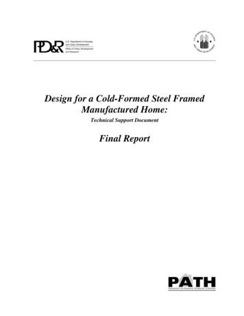
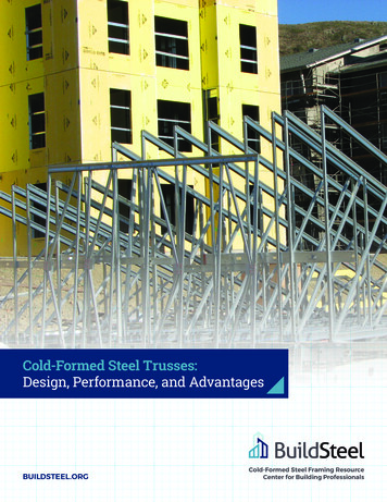
FIGURE 7.1: Various shapes of cold-formed steel sections. (From Yu, W.W. 1991. Cold-Formed SteelDesign, John Wiley & Sons, New York. With permission.)The use of cold-formed steel members in building construction began in the 1850s in both the U.S.and Great Britain. However, such steel members were not widely used in buildings in the U.S. untilthe 1940s. At the present time, cold-formed steel members are widely used as construction materialsworldwide.Compared with other materials such as timber and concrete, cold-formed steel members can offerthe following advantages: (1) lightness, (2) high strength and stiffness, (3) ease of prefabrication andmass production, (4) fast and easy erection and installation, and (5) economy in transportation andhandling, just to name a few.From the structural design point of view, cold-formed steel members can be classified into twomajor types: (1) individual structural framing members (Figure 7.2) and (2) panels and decks(Figure 7.3).In view of the fact that the major function of the individual framing members is to carry load,structural strength and stiffness are the main considerations in design. The sections shown inFigure 7.2 can be used as primary framing members in buildings up to four or five stories in height.In tall multistory buildings, the main framing is typically of heavy hot-rolled shapes and the secondaryelements such as wall studs, joists, decks, or panels may be of cold-formed steel members. In thiscase, the heavy hot-rolled steel shapes and the cold-formed steel sections supplement each other.The cold-formed steel sections shown in Figure 7.3 are generally used for roof decks, floor decks,wall panels, and siding material in buildings. Steel decks not only provide structural strength to carryloads, but they also provide a surface on which flooring, roofing, or concrete fill can be applied asshown in Figure 7.4. They can also provide space for electrical conduits. The cells of cellular panelsc1999 by CRC Press LLC
FIGURE 7.2: Cold-formed steel sections used for structural framing. (From Yu, W.W. 1991. ColdFormed Steel Design, John Wiley & Sons, New York. With permission.)FIGURE 7.3: Decks, panels, and corrugated sheets. (From Yu, W.W. 1991. Cold-Formed Steel Design,John Wiley & Sons, New York. With permission.)can also be used as ducts for heating and air conditioning. For composite slabs, steel decks are usednot only as formwork during construction, but also as reinforcement of the composite system afterthe concrete hardens. In addition, load-carrying panels and decks not only withstand loads normalto their surface, but they can also act as shear diaphragms to resist forces in their own planes if theyare adequately interconnected to each other and to supporting members.During recent years, cold-formed steel sections have been widely used in residential constructionand pre-engineered metal buildings for industrial, commercial, and agricultural applications. Metalbuilding systems are also used for community facilities such as recreation buildings, schools, andchurches. For additional information on cold-formed steel structures, see Yu [49], Rhodes [36], andHancock [28].7.2Design StandardsDesign standards and recommendations are now available in Australia [39], Austria [31], Canada [19],Czechoslovakia [21], Finland [26], France [20], Germany [23], India [30], Japan [14], The Netherlands [27], New Zealand [40], The People’s Republic of China [34], The Republic of South Africa [38],Sweden [44], Romania [37], U.K. [17], U.S. [7], USSR [41], and elsewhere. Since 1975, the EuropeanConvention for Constructional Steelwork [24] has prepared several documents for the design andc1999 by CRC Press LLC
FIGURE 7.4: Cellular floor decks. (From Yu, W.W. 1991. Cold-Formed Steel Design, John Wiley &Sons, New York. With permission.)testing of cold-formed sheet steel used in buildings. In 1989, Eurocode 3 provided design informationfor cold-formed steel members.This chapter presents discussions on the design of cold-formed steel structural members for use inbuildings. It is mainly based on the current AISI combined specification [7] for allowable stress design(ASD) and load and resistance factor design (LRFD). It should be noted that in addition to the AISIspecification, in the U.S., many trade associations and professional organizations have issued specialdesign requirements for using cold-formed steel members as floor and roof decks [42], roof trusses [6],open web steel joists [43], transmission poles [10], storage racks [35], shear diaphragms [7, 32],composite slabs [11], metal buildings [33], light framing systems [15], guardrails, structural supportsfor highway signs, luminaries, and traffic signals [4], automotive structural components [5], andothers. For the design of cold-formed stainless steel structural members, see ASCE Standard 890 [12].7.3Design BasesFor cold-formed steel design, two design approaches are being used. They are: (1) ASD and (2) LRFD.Both methods are briefly discussed in this section.7.3.1Allowable Stress Design (ASD)In the ASD approach, the required strengths (moments, axial forces, and shear forces) in structuralmembers are computed by accepted methods of structural analysis for the specified nominal orworking loads for all applicable load combinations listed below [7].1. D2. D L (Lr or S or Rr )c1999 by CRC Press LLC
3. D (W or E)4. D L (Lr or S or Rr ) (W or E)whereD dead loadE earthquake loadL live load due to intended use and occupancyLr roof live loadRr rain load, except for pondingS snow loadW wind loadIn addition, due consideration should also be given to the loads due to (1) fluids with well-definedpressure and maximum heights, (2) weight and lateral pressure of soil and water in soil, (3) ponding,and (4) contraction or expansion resulting from temperature, shrinkage, moisture changes, creep incomponent materials, movement due to different settlement, or combinations thereof.The required strengths should not exceed the allowable design strengths permitted by the applicabledesign standard. The allowable design strength is determined by dividing the nominal strength by asafety factor as follows:(7.1)Ra Rn / whereRa allowable design strengthRn nominal strength safety factorFor the design of cold-formed steel structural members using the AISI ASD method [7], the safetyfactors are given in Table 7.1.When wind or earthquake loads act in combination with dead and/or live loads, it has been a generalpractice to permit the allowable design strength to be increased by a factor of one-third because theaction of wind or earthquake on a structure is highly localized and of very short duration. Thiscan also be accomplished by permitting a 25% reduction in the combined load effects without theincrease of the allowable design strength.7.3.2Limit States Design or Load and Resistance Factor Design (LRFD)Two types of limit states are considered in the LRFD method. They are: (1) the limit state ofstrength required to resist the extreme loads during the life of the structure and (2) the limit state ofserviceability for a structure to perform its intended function.For the limit state of strength, the general format of the LRFD method is expressed by the followingequation:(7.2)6γi Qi φRnwhere6γi QiφRnγi required strength design strength load factors load effectsQiφ resistance factor nominal strengthRnThe load factors and load combinations are specified in various standards. According to the AISISpecification [7], the following load factors and load combinations are used for cold-formed steeldesign:c1999 by CRC Press LLC
TABLE 7.1 Safety Factors, , and Resistance Factors, φ , used in the AISISpecification [7]Type of strength(a) StiffenersTransverse stiffenersShear stiffenersa(b) Tension members (see also bolted connections)(c) Flexural membersBending strengthFor sections with stiffened or partially stiffenedcompression flangesFor sections with unstiffened compression flangesLaterally unbraced beamsBeams having one flange through-fastened to deck orsheathing (C- or Z-sections)Beams having one flange fastened to a standing seam roof systemWeb designShear strengthaWeb cripplingFor single unreinforced websFor I-sectionsFor two nested Z-sections(d) Concentrically loaded compression members(e) Combined axial load and bendingFor tensionFor compressionFor bending(f) Cylindrical tubular membersBending strengthAxial compression(g) Wall studs and wall assembliesWall studs in compressionWall studs in bending(h) Diaphragm construction(i) Welded connectionsGroove weldsTension or compressionShear (welds)Shear (base metal)Arc spot weldsWeldsConnected partMinimum edge distanceTensionArc seam weldsWeldsConnected partFillet weldsLongitudinal loading (connected part)Transverse loading (connected part)WeldsFlare groove weldsTransverse loading (connected part)Longitudinal loading (connected part)WeldsResistance Welds(j) Bolted connectionsMinimum spacing and edge distanceTension strength on net sectionWith washersDouble shear connectionSingle shear connectionWithout washersBearing strengthShear strength of boltsTensile strength of bolts(k) Screw connections(l) Shear rupture(m) Connections to other materials (Bearing)a When h/t 0.96pEk /F , 1.50,φ 1.0v yc1999 by CRC Press LLCASDsafetyfactor, LRFDresistancefactor, 50.550.650.55-0.700.650.750.500.750.60
1.2.3.4.5.6.1.4D L1.2D 1.6L 0.5(Lr or S or Rr )1.2D 1.6(Lr or S or Rr ) (0.5L or 0.8W )1.2D 1.3W 0.5L 0.5(Lr or S or Rr )1.2D 1.5E 0.5L 0.2S0.9D (1.3W or 1.5E)All symbols were defined previously.Exceptions:1. The load factor for E in combinations (5) and (6) should be equal to 1.0 when the seismicload model specified by the applicable code or specification is limit state based.2. The load factor for L in combinations (3), (4), and (5) should be equal to 1.0 for garages,areas occupied as places of public assembly, and all areas where the live load is greaterthan 100 psf.3. For wind load on individual purlins, girts, wall panels, and roof decks, multiply the loadfactor for W by 0.9.4. The load factor for Lr in combination (3) should be equal to 1.4 in lieu of 1.6 when theroof live load is due to the presence of workmen and materials during repair operations.In addition, the following LRFD criteria apply to roof and floor composite construction usingcold-formed steel:1.2Ds 1.6Cw 1.4CwhereDs weight of steel deckCw weight of wet concrete during constructionC construction load, including equipment, workmen, and formwork, but excluding theweight of the wet concrete.Table 7.1 lists the φ factors, which are used for the AISI LRFD method for the design of coldformed steel members and connections [7]. It should be noted that different load factors andresistance factors may be used in different standards. These factors are selected for the specificnominal strength equations adopted by the given standard or specification.7.4Materials and Mechanical PropertiesIn the AISI Specification [7], 14 different steels are presently listed for the design of cold-formed steelmembers. Table 7.2 lists steel designations, ASTM designations, yield points, tensile strengths, andelongations for these steels.From a structural standpoint, the most important properties of steel are as follows:1.2.3.4.5.6.7.cYield point or yield strength, FyTensile strength, FuStress-strain relationshipModulus of elasticity, tangent modulus, and shear modulusDuctilityWeldabilityFatigue strength1999 by CRC Press LLC
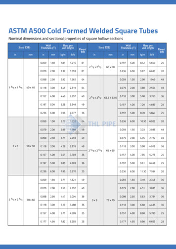
TABLE 7.2Mechanical Properties of Steels Referred to in the AISI 1996 SpecificationElongation (%)Steel designationStructural steelHigh-strength low-alloystructural steelLow and intermediatetensile strengthcarbon plates, shapesand barsCold-formed weldedand seamless carbonsteel structural tubingin rounds and shapesStructural steel with 42 ksiminimum yield pointHot-rolled carbon steelsheets and strips ofstructural qualityHigh-strength low-alloycolumbium-vanadiumsteels of structuralqualityHigh-strength low-alloystructural steel with50 ksi minimum yield pointHot-rolled and cold-rolledhigh-strength low-alloysteel sheet and strip withimproved corrosion resistanceHot-rolled and cold-rolledhigh-strength low-alloycolumbium and/or vanadiumsteel sheet and stripCold-rolled carbonstructural steel sheetc1999 by CRC Press LLCYieldpoint, Fy(ksi)Tensilestrength, Fu(ksi)In 2-in.gagelengthIn 8-in.gagelengthA36A242 (3/4 in.and under)(3/4 in. to1-1/2 in.)A283 Gr. ABCDA500Round tubingABCDShaped tubingABCDA529 Gr. 23——————1918A570 Gr. 303336404550A572 Gr. ��————2018161518456522—50457060 (55)—505065 (60)555570 (65)606075 (70)656580 (75)707085 (80)2530334080424548528222Hot-rolled 23-25Cold-rolled 22Hot-rolled 20-22Cold-rolled 20Hot-rolled 18-20Cold-rolled 18Hot-rolled 16-18Cold-rolled 16Hot-rolled 14-16Cold-rolled 15Hot-rolled 12-14Cold-rolled 1426242220—ASTMdesignationA606Hot-rolled asrolled coils;annealed, ornormalized; andcold-rolledHot-rolled asrolled cutlengthsA607 Gr. 45A611 Gr. ABCDE———————————————
TABLE 7.2 Mechanical Properties of Steels Referred to in the AISI 1996Specification (continued)Elongation (%)Steel designationZinc-coated steel sheetsof structural qualityHot-rolled high-strengthlow-alloy steel sheetsand strip with improvedformabilityAluminum-zincalloy-coated by thehot-dip processgeneral requirementsASTMdesignationYieldpoint, Fy(ksi)Tensilestrength, Fu(ksi)In 2-in.gagelengthIn 8-in.gagelengthA653 SQ Gr. 33374050 (class 1)50 (class 3)80HSLA Gr. 50607080A715 Gr. 50607080A792 Gr. es:1. The tabulated values are based on ASTM Standards.2. 1 in. 25.4 mm; 1 ksi 6.9 MPa.3. A653 Structural Quality Grade 80, Grade E of A611, and Structural Quality Grade 80 of A792 areallowed in the AISI Specification under special conditions. For these grades, Fy 80 ksi, Fu 82 ksi,elongations are unspecified. See AISI Specification for reduction of yield point and tensile strength.4. For A653 steel, HSLA Grades 70 and 80, the elongation in 2-in. gage length given in the parenthesis isfor Type II. The other value is for Type I.5. For A607 steel, the tensile strength given in the parenthesis is for Class 2. The other value is for Class 1.In addition, formability, durability, and toughness are also important properties for cold-formedsteel.7.4.1Yield Point, Tensile Strength, and Stress-Strain RelationshipAs listed in Table 7.2, the yield points or yield strengths of all 14 different steels range from 24 to 80 ksi(166 to 552 MPa). The tensile strengths of the same steels range from 42 to 100 ksi (290 to 690 MPa).The ratios of the tensile strength-to-yield point vary from 1.12 to 2.22. As far as the stress-strainrelationship is concerned, the stress-strain curve can either be the sharp-yielding type (Figure 7.5a)or the gradual-yielding type (Figure 7.5b).7.4.2Strength Increase from Cold Work of FormingThe mechanical properties (yield point, tensile strength, and ductility) of cold-formed steel sections,particularly at the corners, are sometimes substantially different from those of the flat steel sheet,strip, plate, or bar before forming. This is because the cold-forming operation increases the yieldpoint and tensile strength and at the same time decreases the ductility. The effects of cold-work onthe mechanical properties of corners usually depend on several parameters. The ratios of tensilestrength-to-yield point, Fu /Fy , and inside bend radius-to-thickness, R/t, are considered to be themost important factors to affect the change in mechanical properties of cold-formed steel sections.Design equations are given in the AISI Specification [7] for computing the tensile yield strength ofcorners and the average full-section tensile yield strength for design purposes.c1999 by CRC Press LLC
FIGURE 7.5: Stress-strain curves of steel sheet or strip. (a) Sharp-yielding. (b) Gradual-yielding.(From Yu, W.W. 1991. Cold-Formed Steel Design, John Wiley & Sons, New York. With permission.)7.4.3Modulus of Elasticity, Tangent Modulus, and Shear ModulusThe strength of cold-formed steel members that are governed by buckling depends not only on theyield point but also on the modulus of elasticity, E, and the tangent modulus, Et . A value of E 29,500 ksi (203 GPa) is used in the AISI Specification for the design of cold-formed steel structuralmembers. This E value is slightly larger than the value of 29,000 ksi (200 GPa), which is being usedin the AISC Specification for the design of hot-rolled shapes. The tangent modulus is defined by theslope of the stress-strain curve at any given stress level as shown in Figure 7.5b. For sharp-yieldingsteels, Et E up to the yield, but with gradual-yielding steels, Et E only up to the proportionallimit, fpr (Figure 7.5b). Once the stress exceeds the proportional limit, the tangent modulus Etbecomes progressively smaller than the initial modulus of elasticity. For cold-formed steel design,the shear modulus is taken as G 11,300 ksi (77.9 GPa) according to the AISI Specification.7.4.4DuctilityAccording to the AISI Specification, the ratio of Fu /Fy for the steels used for structural framingmembers should not be less than 1.08, and the total elongation should not be less than 10% for a2-in. (50.8 mm) gage length. If these requirements cannot be met, an exception can be made forpurlins and girts for which the following limitations should be satisfied when such a material is used:(1) local elongation in a 1/2-in. (12.7 mm) gage length across the fracture should not be less than20% and (2) uniform elongation outside the fracture should not be less than 3%. It should be notedthat the required ductility for cold-formed steel structural members depends mainly on the typeof application and the suitability of the material. The same amount of ductility that is considerednecessary for individual framing members may not be needed for roof panels, siding, and similarapplications. For this reason, even though Structural Grade 80 of ASTM A653 steel, Grade E of A611c1999 by CRC Press LLC
steel, and Grade 80 of A792 steel do not meet the AISI requirements of the Fu /Fy ratio and theelongation, these steels can be used for roofing, siding, and similar applications provided that (1) theyield strength, Fy , used for design is taken as 75% of the specified minimum yield point or 60 ksi(414 MPa), whichever is less, and (2) the tensile strength, Fu , used for design is taken as 75% of thespecified minimum tensile stress or 62 ksi (427 MPa), whichever is less.7.5Element StrengthFor cold-formed steel members, the width-to-thickness ratios of individual elements are usuallylarge. These thin elements may buckle locally at a stress level lower than the yield point of steel whenthey are subject to compression in flexural bending and axial compression as shown in Figure 7.6.Therefore, for the design of such thin-walled sections, local buckling and postbuckling strength ofthin elements have often been the major design considerations. In addition, shear buckling and webcrippling should also be considered in the design of beams.FIGURE 7.6: Local buckling of compression elements. (a) Beams. (b) Columns. (From Yu, W.W.1991. Cold-Formed Steel Design, John Wiley & Sons, New York. With permission.)7.5.1Maximum Flat-Width-to-Thickness RatiosIn cold-formed steel design, the maximum flat-width-to-thickness ratio, w/t, for flanges is limitedto the following values in the AISI Specification:1. Stiffened compression element having one longitudinal edge connected to a web or flangeelement, the other stiffened bySimple lip . . . . . . . . . . . . . . . . . . . . . . . . . . . . . . . . . . . . . . . . . . . . . . . . . . . . . . . . . . . . . . 60Any other kind of stiffener . . . . . . . . . . . . . . . . . . . . . . . . . . . . . . . . . . . . . . . . . . . . . . . 902. Stiffened compression element with both longitudinal edges connected to other stiffenedelement . . . . . . . . . . . . . . . . . . . . . . . . . . . . . . . . . . . . . . . . . . . . . . . . . . . . . . . . . . . . . . . . . . . . 500c1999 by CRC Press LLC
3. Unstiffened compression element and elements with an inadequate edge stiffener . . . 60For the design of beams, the maximum depth-to-thickness ratio, h/t, for webs are:1. For unreinforced webs: (h/t)max 2002. For webs that are provided with transverse stiffeners:Using bearing stiffeners only: (h/t)max 260Using bearing stiffeners and intermediate stiffeners: (h/t)max 3007.5.2Stiffened Elements under Uniform CompressionThe strength of a stiffened compression element such as the compression flange of a hat section isgoverned by yielding if its w/t ratio is relatively small. It may be governed by local buckling as shownin Figure 7.7 at a stress level less than the yield point if its w/t ratio is relatively large.FIGURE 7.7: Local buckling of stiffened compression flange of hat-shaped beam.The elastic local buckling stress, fcr , of simply supported square plates and long plates can bedetermined as follows:kπ 2 E(7.3)fcr 12(1 µ2 )(w/t)2wherek local buckling coefficientE modulus of elasticity of steel 29.5 103 ksi (203 GPa)w width of the platet thickness of the plateµ Poisson’s ratioIt is well known that stiffened compression elements will not collapse when the local buckling stressis reached. An additional load can be carried by the element after buckling by means of a redistributionof stress. This phenomenon is known as postbuckling strength and is most pronounced for elementswith large w/t ratios.The mechanism of the postbuckling action can be easily visualized from a square plate model asshown in Figure 7.8 [48]. It represents the portion abcd of the compression flange of the hat sectionillustrated in Figure 7.7. As soon as the plate starts to buckle, the horizontal bars in the grid of themodel will act as tie rods to counteract the increasing deflection of the longitudinal struts.In the plate, the stress distribution is uniform prior to its buckling. After buckling, a portionof the prebuckling load of the center strip transfers to the edge portion of the plate. As a result, ac1999 by CRC Press LLC
FIGURE 7.8: Postbuckling strength model. (From Yu, W.W. 1991. Cold-Formed Steel Design, JohnWiley & Sons, New York. With permission.)nonuniform stress distribution is developed, as shown in Figure 7.9. The redistribution of stresscontinues until the stress at the edge reaches the yield point of steel and then the plate begins to fail.FIGURE 7.9: Stress distribution in stiffened compression elements.For cold-formed steel members, a concept of “effective width” has been used for practical design.In this approach, instead of considering the nonuniform distribution of stress over the entire widthof the plate, w, it is assumed that the total load is carried by a fictitious effective width, b, subjectedto a uniformly distributed stress equal to the edge stress, fmax , as shown in Figure 7.9. The width, b,is selected so that the area under the curve of the actual nonuniform stress distribution is equal to thesum of the two parts of the equivalent rectangular shaded area with a total width, b, and an intensityof stress equal to the edge stress, fmax . Based on the research findings of von Karman, Sechler, andDonnell [45], and Winter [47], the following equations have been developed in the AISI Specificationfor computing the effective design width, b, for stiffened elements under uniform compression [7]:(a) Strength Determinationc1999 by CRC Press LLC1. When λ 0.673, b w(7.4)2. When λ 0.673, b ρw(7.5)
whereb effective design width of uniformly compressed element for strength determination (Figure 7.10)w flat width of compression elementρ reduction factor determined from Equation 7.6:ρ (1 0.22/λ)/λ 1where λ plate slenderness factor determined from Equation 7.7:p λ (1.052/ k)(w/t)( f/E)(7.6)(7.7)wherek plate buckling coefficient 4.0 for stiffened elements supported by a web on each longitudinaledge as shown in Figure 7.10t thickness of compression elementE modulus of elasticityf maximum compressive edge stress in the element without considering the safety factorFIGURE 7.10: Effective design width of stiffened compression elements.(b) Deflection DeterminationFor deflection determination, Equations 7.4 through 7.7 can also be used for computing the effectivedesign width of compression elements, except that the compressive stress should be computed onthe basis of the effective section at the load for which deflection is calculated.The relationship between ρ and λ according to Equation 7.6 is shown in Figure 7.11.EXAMPLE 7.1:Calculate the effective width of the compression flange of the box section (Figure 7.12) to be usedas a beam bending about the x-axis. Use Fy 33 ksi. Assume that the beam webs are fully effectiveand that the bending moment is based on initiation of yielding.Solution Because the compression flange of the given section is a uniformly compressedstiffened element, which is supported by a web on each longitudinal edge, the effective width of theflange for strength determination can be computed by using Equations 7.4 through 7.7 with k 4.0.Assume that the bending strength of the section is based on Initiation of Yielding, ȳ 2.50 in.Therefore, the slenderness factor λ for f Fy can be computed from Equation 7.7, i.e.,c1999 by CRC Press LLCkw 4.06.50 2(R t) 6.192 in.w/t 103.2
FIGURE 7.11: Reduction factor, ρ, vs. slenderness factor, λ. (From Yu, W.W. 1991. Cold-FormedSteel Design, John Wiley & Sons, New York. With permission.)FIGURE 7.12: Example 7.1. (From Yu, W.W. 1991. Cold-Formed Steel Design, John Wiley & Sons,New York. With permission.)f λ 33 ksip (1.052/ k)(w/t) f/Ep (1.052/ 4.0)(103.2) 33/29,500 1.816Since λ 0.673, use Equations 7.5 and 7.6 to compute the effective width, b, as follows:bc1999 by CRC Press LLC ρw [(1 0.22/λ)/λ]w [(1 0.22/1.816)/1.816](6.192) 3.00 in.
7.5.3Stiffened Elements with Stress GradientWhen a flexural member is subject to bending moment, the beam web is under the stress gradientcondition (Figure 7.13), in which the compression portion of the web may buckle due to the compressive stress caused by bending. The effective width of the beam web can be determined from thefollowing AISI provisions:FIGURE 7.13: Stiffened elements with stress gradient.(a) Strength DeterminationThe effective widths, b1 and b2 , as shown in Figure 7.13, should be determined from the followingequations:(7.8)b1 be /(3 ψ)For ψ 0.236b2 be /2(7.9)b1 b2 should not exceed the compression portion of the web calculated on the basis of effectivesection.For ψ 0.236(7.10)b2 be b1where be effective width b determined by Equation 7.4 or Equation 7.5 with f1 substituted for fand with k determined as follows:kψ 4 2(1 ψ)3 2(1 ψ) f2 /f1(7.11)(7.12)f1 , f2 stresses shown in Figure 7.13 calculated on the basis of effective section. f1 is compression( ) and f2 can be either tension ( ) or compression. In case f1 and f2 are both compression,f1 f2(b) Deflection Determi
elements such as wall studs, joists, decks, or panels may be of cold-formed steel members. In this case, the heavy hot-rolled steel shapes and the cold-formed steel sections supplement each other. The cold-formed steel sections shown in Figure 7.3 are generally used for roof de