Transcription
SEISMIC RESTRAINT DESIGN MANUALEXPERIENCE · QUALITY · SERVICEWWW.SASCOCAN.COMManufactured in Canada Since 1974
SASCO STRUT – SEISMIC RESTRAINT DESIGN MANUALTable of Contents1. General Information . 22. Design Procedure . 113. Figures . 184. Design Tables . 275. Design Examples . 346. Notation . 457. Parts . 47The information in this manual is subject to Read Jones Chrisoffersen Ltd.'s Structural Engineering Disclaimer foundon Page 1 of this Manual
Structural Engineering DisclaimerRead Jones Christoffersen Ltd. (RJC) has collaboratedcorroborated on and reviewed thismanual for the design procedures for seismically bracing non-structural buildingcomponents and has provided supplementary design tables derived from theNational Building Code of Canada (2010 Edition).This manual is intended for use by a qualified person who takes full responsibilityfor the project design. Anyone using the information in this publication assumesany and all liability resulting from such use. Sasco and RJC disclaim any and allexpress or implied warranties of fitness for any general or particular application.Final responsibility for the structural adequacy of the support of non-structuralelements on any given project rests with the professional engineer for that projectwho shall also determine compliance with all applicable federal, provincial andmunicipal codes.Gilbert Raynard, P.Eng., Struct Eng.PrincipalRead Jones Christoffersen Ltd.Suite 3001285 West BroadwayVancouver, BC V6H 3X8Canada604 738-0048738Fax 604 738-1107738www.rjc.caSasco Seismic Restraint ManualThe informationin thisinmanualis subject toJonestoChristoffersenLtd.’sstructural engineeringfoundEngineeringon page 1 of thisDisclaimermanual.Theinformationthis manualis ReadsubjectRead n Page 1 of this Manual1
1. General InformationIn response to requests for a Seismic Restraint Design Manual based on theCanadian method of limit states design which compares factored resistance tofactored load, Sasco Tubes and Roll Forming Inc. (Sasco) engaged Read JonesChristoffersen Ltd. (RJC), a large Canadian consulting structural engineeringcompany, to create this publication for use in Canada.Sasco, a Canadian owned and operated company, is recognized as Canada’sindustry leader with over 40 years of experience in manufacturing a complete lineof strut channel and fittings for electrical, mechanical, industrial and seismicapplications.The material provided in this publication is for general information only andis to be used as a reference tool.Seismic bracing systems designed and detailed in this publication do notguarantee the adequacy of existing structures to withstand the loadstransmitted by the seismic bracing system.Final responsibility for the structural adequacy of the support of nonstructural elements as well as the adequacy of the existing structures restswith the designer and/or project engineer who must also determinecompliance with all applicable codes.Anyone using the information in this publication assumes any and allliability resulting from such use. Sasco and RJC disclaim any and allexpress or implied warranties of fitness for any general or particularapplication.The information provided in this publication is specifically intended for use in theseismic bracing of non-structural building components in Canada and derivedfrom the 2010 edition of the National Building Code of Canada (NBCC).Provincial and municipal codes may also apply and the designer of record shallconfirm that all applicable code requirements are satisfied. The design of thestructural braces and their attachments are based on the limits states designprocedure as required by the NBCC and the tables in this document providedesign information in both metric and imperial units. Where applicable, the designrecommendations presented within represent “best practices” in Canada.Sasco Seismic Restraint ManualThe informationin thisinmanualis subject toJonestoChristoffersenLtd.’sstructural engineeringfoundEngineeringon page 1 of thisDisclaimermanual.Theinformationthis manualis ReadsubjectRead n Page 1 of this Manual2
Notes: Design recommendations provided are shown for standard weight steel pipesfilled with water. Contents other than water shall be evaluated by the projectengineer and pipes of other materials shall be supported in accordance withtheir approved installation standards This publication does not address the seismic design of the pipes themselves. Refer to the Sheet Metal and Air Conditioning Contractors NationalAssociation (SMACNA) “Seismic Restraint Manual: Guidelines for MechanicalSystems” (ANSI /SMACNA 001-2000) for additional guidelines on seismicbracing. Section 4.2 of the SMACNA document is provided herein (on pages7 to 10) for assistance with laying out transverse and longitudinal braces. See the National Plumbing Code of Canada for more information on pipesupports See clause 4.1.8.18 of the NBCC for additional information regarding seismicdesign requirements for non-structural components and equipment.Requirements: Seismic bracing shall not limit the expansion and contraction of the pipingsystem; the engineer of record shall ascertain that consideration is given tothe individual dynamic and thermal properties of these systems and thebuilding structure. Where possible, pipes and conduit and their connections shall be constructedof ductile materials such as copper, ductile iron, steel or aluminum Transverse and longitudinal braces shall be placed no more than 45 from thehorizontal (see Figures 2 (Pg 20) and 4 Pg (21)) Where rod stiffeners are required, a minimum of two Sasco rod stiffenerclamps shall be installed (see Figure 6 Pg (22)) Braces for trapeze hangers shall be connected directly to the trapeze hangerand all pipes shall be secured to the trapeze with approved Sasco pipeclamps (See Pg 44) Longitudinal bracing of trapezes shall have a brace on both ends of thetrapeze All bolts and Sasco clamping nuts shall be ½” (12.7 mm) diameterSasco Seismic Restraint ManualThe informationin thisinmanualis subject toJonestoChristoffersenLtd.’sstructural engineeringfoundEngineeringon page 1 of thisDisclaimermanual.Theinformationthis manualis ReadsubjectRead n Page 1 of this Manual3
Material SpecificationsItemStandardChannel SectionsASTM A653/653M SS Grade 33, GalvanizedBoltsASTM A307Clamping NutsASTM A108 Grades 1015 and 1020Threaded RodASTM A36, A575 or A576Bolt Torque½” (12.7 mm) bolts must be tightened to a minimum torque of 68 N.m (50 ft.lbs)when used with Sasco clamping nuts.Sasco Seismic Restraint ManualThe informationin thisinmanualis subject toJonestoChristoffersenLtd.’sstructural engineeringfoundEngineeringon page 1 of thisDisclaimermanual.Theinformationthis manualis ReadsubjectRead n Page 1 of this Manual4
Seismic Design InformationThe following defines the design lateral seismic force, Vp, for elements andcomponents of buildings as described in the 2010 National Building Code ofCanada (NBCC 2005) sentence 4.1.8.18.Vp Seismic Load Coefficient x W pSeismic Load Coefficient 0.3·Fa·Sa(0.2)·IE·SpwhereFaSa(0.2) IE Sp CpArAxRpWp as defined in NBCC Table 4.1.8.4.B.,spectral response acceleration value at 0.2 s, asdefined in NBCC sentence 4.1.8.4.(1),importance factor for the building, as defined inNBCC Article 4.1.8.5Cp·Ar·Ax/Rp (the maximum value of Sp shall betaken as 4.0 and the minimum value of Sp shall betaken as 0.7) element or component factor from NBCCTable 4.1.8.18 element or component force amplificationfactor from NBCC Table 4.1.8.18 height factor (1 2 hx/hn), wherehx height of component under designconsiderationhn height of uppermost level in main portionof structure (see Figure 9) Element or component response modificationfactor from NBCC Table 4.1.8.18weight of component or elementNote the following typical seismic loading criteria:1) Assume importance factor of 1.5 unless noted otherwise2) If Site Class information is unknown, the NBCC requires that thehighest value of Fa for a given Sa(0.2) found in the table for Fa shall beused.3) The lateral seismic force in the transverse direction may be consideredto act independently of forces in the longitudinal direction and vice versa.See Figure 10 (Pg 24) for values of Ar, Rp, and Cp for mechanical and electricalcomponents in a typical building in Vancouver.Sasco Seismic Restraint ManualThe informationin thisinmanualis subject toJonestoChristoffersenLtd.’sstructural engineeringfoundEngineeringon page 1 of thisDisclaimermanual.Theinformationthis manualis ReadsubjectRead n Page 1 of this Manual5
Load CombinationsAs required in the NBCC, the effect of factored loads for a building or structuralcomponent shall be determined in accordance with the Code and the LoadCombination cases outlined therein. From the NBCC, the following loads andLoad Combination applies:Load Combination:1.0D 1.0EWhere: D is the Dead load of the system including the weight of the pipes andtheir contentsandE is the load due to EarthquakeAnchorage to Base StructureIt is the responsibility of the project engineer to confirm that the primary structurecan withstand the connection loads of the hanger rods and brace attachments.The design of these connections is the responsibility of the project engineer andshould be reviewed by the engineer of record for the base building. See NBCCclause 4.1.8.18 (8) for additional connection information. See Figures 11 (Pg 25)and 12 (Pg 26) for common concrete and steel connectionsSasco Seismic Restraint ManualThe informationin thisinmanualis subject toJonestoChristoffersenLtd.’sstructural engineeringfoundEngineeringon page 1 of thisDisclaimermanual.Theinformationthis manualis ReadsubjectRead n Page 1 of this Manual6
SMACNA – Section 4.2The following is taken from section 4.2 of the Sheet Metal and Air ConditioningContractors National Association (SMACNA) “Seismic Restraint Manual:Guidelines for Mechanical Systems” (ANSI /SMACNA 001-2000). It is providedfor additional guidelines on seismic bracing of non-structural components within abuilding. Note: the project engineer must ensure that the most current version ofSMACNA document is referred to which may supersede the information below.1. Separate the length of the pipe into separate runs. A run is considered to be asingle straight section between any bends in the pipe except where the bend is atan offset of less than the allowable transverse brace spacing (sbt) divided by 16.Note: The maximum transverse brace spacing is shown in Table 3 (Pg 29).WHERETHEOFFSETIS MORETHANS/16 s /16WHERETHEOFFSETIS MORETHANWHERE THEOFFSETIS MORETHANS/16 btTHEN TREAT EACH SIDE OF THE OFFSET ASTHENTREATEACHEACHSIDEOFFSETTHEN TREATSIDEOF OFTHETHEOFFSETAS ASA SEPARATE PIPE RUNA SEPARATESEPARATE PIPERUNAPIPERUN2. Each straight run must be braced in the transverse direction at each end.Where several short runs occur, see item 5 below.PIPE RUNPIPE RUNPIPE RUNTRANSVERSE BRACINGEACH END OF THE PIPE RUNTRANSVERSE BRACINGTRANSVERSE BRACINGEACH END OF THE PIPE RUNEACH END OF THE PIPE RUNSasco Seismic Restraint ManualThe informationin thisinmanualis subject toJonestoChristoffersenLtd.’sstructural engineeringfoundEngineeringon page 1 of thisDisclaimermanual.Theinformationthis manualis ReadsubjectRead n Page 1 of this Manual7
3. Check the spacing of the transverse bracing with the braces at each end of thepipe run. If this distance is greater than the allowable distance in Table 3 (Pg29), add transverse braces until the spacing does not exceed the allowabledistance.PIPE RUNPIPE RUNADDITIONALADDITIONALTRANSVERSE BRACESTRANSVERSE BRACESLONGITUDINAL BRACES(USE TRANSVERSEBRACELONGITUDINALBRACESAT THEADJACENTBRACERUN)(USETRANSVERSEAT THE ADJACENT RUN)PIPE RUNPIPE RUNLONGITUDINAL BRACELONGITUDINAL BRACE24" (610mm)24" (610mm)MAX.MAX.24" (610mm)24" (610mm)MAX.MAX.4. Each pipe run must have at least one longitudinal brace. Add longitudinalbraces so the spacing does not exceed the maximum spacing in Table 3 (Pg 29).LONGITUDINAL BRACES(USE TRANSVERSEBRACELONGITUDINALBRACESAT THEADJACENTBRACERUN)(USETRANSVERSEAT THE ADJACENT RUN)If an adjacent run has a transverse brace within 610 mm (24in) of the 90 degreecorner, it can be used a longitudinal brace. Use the larger of the two braces, thelongitudinal brace for this run or the transverse brace of the adjacent run.Sasco Seismic Restraint ManualThe informationin thisinmanualis subject toJonestoChristoffersenLtd.’sstructural engineeringfoundEngineeringon page 1 of thisDisclaimermanual.Theinformationthis manualis ReadsubjectRead n Page 1 of this Manual8
5. In many cases, several short sections of pipe occur one after the other. Basedupon the requirements above, each section should be provided with alongitudinal brace if the offset is greater than sbt /16. The longitudinal braces canact as transverse braces as long as the total length of pipe tributary to the bracedoes not exceed sbt.With a layout as shown below, in which each section shown is less than sbt /2long, transverse braces can be used as the longitudinal braces. Where a sectionis longer than sbt /2, additional braces will be required.FIRST TRANSVERSE BRACESECOND TRANSVERSEBRACESECOND TRANSVERSESECOND TRANSVERSEBRACEBRACEFIRST TRANSVERSE BRACEFIRST TRANSVERSE BRACE2 ADDITIONAL BRACES2 ADDITIONAL BRACESMAYBE REQUIRED2 ADDITIONALBRACESMAY BE REQUIREDMAY BE REQUIREDSAMPLEPIPE SECTIONSAMPLE N sbt /2 LONGLESS THAN S/2 LONGSECTIONLONGERSECTIONLONGERSECTIONLONGERTHANsbt LONGITUDINALBRACEWHERE THE TOTAL OFFSET IS 16THEOFFSETCANBELESSIS LESSTHANS/16 sTHEOFFSETCAN BE CAN BETHANTHEOFFSETIGNOREDANDTHESECTIONCAN BEbt /16IGNOREDANDTHESECTIONCAN BECAN BEIGNOREDANDTHE SECTIONTREATEDASONERUN.TREATED AS ONE RUN.TREATED AS ONE RUN.PLAN OR ELEVATION OF PIPEPLAN OR ELEVATION OF PIPEPLAN OR ELEVATION OF PIPESasco Seismic Restraint ManualThe informationin thisinmanualis subject toJonestoChristoffersenLtd.’sstructural engineeringfoundEngineeringon page 1 of thisDisclaimermanual.Theinformationthis manualis ReadsubjectRead n Page 1 of this Manual9
6. The following figure shows a different condition. When a flexible connection orswing joint is used, such as at a pipe drop to mechanical equipment, the pipemay cantilever as much as sbt /2 without adding additional bracing.PIPEPIPEPLANPLANEND OF HORIZONTAL E(PROVIDEA MENTEQUIPMENT(PROVIDEA MENTUNLESS THE PIPE IS BRACED AND THEEQUIPMENT IS RIGIDLY MOUNTED.)HHHPIPE ERSEBRACE AT THEENDENDOFOFHORIZONTALHORIZONTALRUNRUNWHEREWHEREH S/2H RWHERE H sbt /2PROVIDE BRACINGTO THE FLOORSasco Seismic Restraint ManualThe informationin thisinmanualis subject toJonestoChristoffersenLtd.’sstructural engineeringfoundEngineeringon page 1 of thisDisclaimermanual.Theinformationthis manualis ReadsubjectRead n Page 1 of this Manual10
2. Design ProcedureTrapeze HangersStep 1Determine maximum spacing of trapeze hangers and seismicbracesUse Table 3 (Pg 29) to select the maximum support spacing, strapeze,governed by the requirement of the smallest diameter pipe. Use Table3 to select the maximum seismic brace spacing (transverse, sbt, andlongitudinal, sbl) and note that they should be multiples of the trapezespacing.Note: The project engineer must ensure that any other pipesupport spacing requirements that may be required for a specificproject are also met. See also SMACNA Section 4.2 for guidelinesregarding brace layout.Step 2Determine Dead Load, Wp, supported by trapezeUse Table 3 (Pg 29) to determine the dead load of the pipes and theircontents per unit length supported by the trapeze.Wp (DLp x Np)DLp pipe diameter unit dead load (kN/m or lb/ft)Np number of pipes of each diameter.Step 3Calculate seismic forcesUse the Seismic Design Information given on Page 5 to calculate theSeismic Load Coefficient and design lateral seismic force, Vp. Recall,from the Load Combination provided earlier on page 6, the load factorfor load due to earthquake is 1.0In the transverse direction:Vpt 1.0 x Seismic Load Coefficient x W p x sbtIn the longitudinal direction:Vpll 1.0 x Seismic Load Coefficient x W p x sblSasco Seismic Restraint ManualThe informationin thisinmanualis subject toJonestoChristoffersenLtd.’sstructural engineeringfoundEngineeringon page 1 of thisDisclaimermanual.Theinformationthis manualis ReadsubjectRead n Page 1 of this Manual11
Step 4Determine Sasco pipe clamp requiredUse Table 9 (Pg 33) to ensure that each pipe is secured to the trapezewith a clamp that can withstand the applied forces in all threedirections: transverse, longitudinal, and vertical (if applicable). SeeFigure 7 (Pg 22). The resistances (or capacities) for the clamp (Rclamp t,Rclamp ℓ, Rclamp v,) are provided in Table 9 (Page 33) and must exceedthe applied factored forces which are calculated according to thefollowing expressions:Transverse:Rclamp t Fclamp t 1.0 x Seismic Load Coefficient x DLp x sbtLongitudinal:Rclamp ℓ Fclamp ℓ 1.0 x Seismic Load Coefficient x DLp x sbℓVertical:Rclamp v Fclamp v 1.0 x DLp x strapezeStep 5Check trapeze for bending about both axesUse the maximum factored load capacities provided in Tables 4 (Pg30) and 5 (Pg 31) to check the capacity of the trapeze. The projectengineer must determine if the loads are to be considered asdistributed or concentrated. For bending about both axes, the followinginteraction equation must be satisfied:(MfX / MrX) (MfY / MrY) 1.0where:MfX Factored Bending Load about the X-X axis 1.0 x W p x StrapezeMfY Factored Bending Load about the Y-Y axis VplMrX and MrY Maximum Factored Load about the X-X and Y-Y axestaken from Tables 4 and 5.Note: Elastic deflections for the channel sections are also provided inTables 4 and 5. The engineer of record shall ensure that thedeflections are within acceptable criteria for the project. If necessary, alarger section or closer trapeze spacing can be employed to reduce thedeflections.Sasco Seismic Restraint ManualThe informationin thisinmanualis subject toJonestoChristoffersenLtd.’sstructural engineeringfoundEngineeringon page 1 of thisDisclaimermanual.Theinformationthis manualis ReadsubjectRead n Page 1 of this Manual12
Step 6Check seismic bracesUse Table 6 (Pg 32) to ensure the axial capacity of the seismic braceexceeds the axial force. Table 6 provides the factored axial capacity,Pr, for Sasco SR2 channel. The factored axial force in the seismicbrace, Pb, in tension or compression is given by the following: (SeeFigure 3 (Pg 20))In the transverse direction:Pr Pbt Vpt x (1 / cos θt)In the longitudinal direction:Pr Pbl ½ x Vpl x (1 / cos θl)Note: Where possible the braces should be installed at 45 , which isthe maximum angle. See Figure 2 (Pg 20)Step 7Check hinge and connectionsThe connection of the Sasco seismic hinge (see Figure 2 (Pg 20)) tothe seismic brace will be governed by the capacity of the bolt(s) andclamping nut(s). Use Table 8 (Pg 32) to check that the slip resistance,Vslip, of the bolt(s) and clamping nut(s) exceeds the axial force in theseismic brace.The following must be satisfied:Vslip Pb (where Pb is the larger of Pbt and Pbl)Sasco Seismic Restraint ManualThe informationin thisinmanualis subject toJonestoChristoffersenLtd.’sstructural engineeringfoundEngineeringon page 1 of thisDisclaimermanual.Theinformationthis manualis ReadsubjectRead n Page 1 of this Manual13
Step 8Check capacity of hanger rod and requirement for stiffenerassemblyUse Table 7 (Pg 32) to ensure that the factored axial forces (tensionand compression) in the hanger rod do not exceed the factored axialcapacities (Pr rod, Tr rod) See Figure 6 (Pg 30). Table 7 contains thenecessary information to select the required diameter of rod anddetermine if rod stiffeners are required for the compression condition.Note that forces from the transverse and lateral directions can beconsidered independently. The following equations must be satisfied:In the transverse direction:Compression: Pr rod Prod t (Pbt x sin θt) – (½ x W p x strapeze)Tension:Tr rod Trod t (½ x W p x strapeze) (Pbt x sin θt)In the longitudinal direction:Compression: Pr rod Prod l (Pbl x sin θl) – (½ x W p x strapeze)Tension:Tr rod Trod l (½ x W p x strapeze) (Pbl x sin θl)If Prod t and/or Prod l 0, and the length of the rod exceeds themaximum clamp spacing shown in Table 7, then stiffener clamps mustbe added as shown in Figure 6.Step 9Check anchorages to base structureIt is the responsibility of the project engineer to confirm that theprimary structure can withstand the connection loads of the hangerrods and brace attachments. The design of these connections is theresponsibility of the project engineer and should be reviewed by theengineer of record for the base building. See NBCC clause 4.1.8.18(8) for additional connection information. See Figures 11 (Pg 25) and12 (Pg 26) for common steel and concrete connectionsSasco Seismic Restraint ManualThe informationin thisinmanualis subject toJonestoChristoffersenLtd.’sstructural engineeringfoundEngineeringon page 1 of thisDisclaimermanual.Theinformationthis manualis ReadsubjectRead n Page 1 of this Manual14
Single Pipe HangersStep 1Determine maximum spacing of pipe hanger and seismic bracesUse Table 3 (Pg 29) to select the maximum support spacing, shanger.Use Table 3 to select the maximum seismic brace spacing (transverse,sbt, and longitudinal, sbl) and note that they should be multiples of thehanger spacing.Note: The project engineer must ensure that any other pipesupport spacing requirements that may be required for a specificproject are also met.Step 2Determine Dead Load, Wp, supported by pipe hangerUse Table 3 (Pg 29) to determine the dead load of the pipe and itscontents per unit length.Wp DLpStep 3Calculate seismic forcesUse the Seismic Design Information given on Page 5 to calculate theSeismic Load Coefficient and design lateral seismic force, Vp. Recall,from the load combination provided on page 6, the load factor for loaddue to earthquake is 1.0In the transverse direction:Vpt 1.0 x Seismic Load Coefficient x W p x sbtIn the longitudinal direction:Vpl 1.0 x Seismic Load Coefficient x W p x sblStep 4Determine pipe hanger requiredThe project engineer must ensure that the pipe hanger can withstandthe following factored forces: (see Figure 8 (Pg 23))Transverse:Longitudinal:Vertical:Fhang t VptFhang l VplFhang v 1.0 x W p x shangerWhere shanger is the spacing of pipe hangersSasco Seismic Restraint ManualThe informationin thisinmanualis subject toJonestoChristoffersenLtd.’sstructural engineeringfoundEngineeringon page 1 of thisDisclaimermanual.Theinformationthis manualis ReadsubjectRead n Page 1 of this Manual15
Step 5Check seismic bracesUse Table 6 (Pg 32) to ensure the axial capacity of the seismic braceexceeds the axial force. Table 6 provides the factored axial capacity,Pr, for the Sasco SR2 channel. The factored axial force in the seismicbrace, Pb, in tension or compression is given by the following: (SeeFigure 5 (Pg 21))In the transverse direction:Pr Pbt Vpt x (1 / cos θt)In the longitudinal direction:Pr Pbl Vpl x (1 / cos θl)Note: Where possible the braces should be installed at 45 , this is themaximum angle. See Figure 4 (Pg 21)Step 6Check hinge and connectionsThe connection of the Sasco seismic hinge (see Figure 4 (Pg 21)) tothe seismic brace will be governed by the capacity of the bolt(s) andclamping nut(s). Use Table 8 (Pg 32) to check that the slip resistance,Vslip, of the bolt(s) and clamping nut(s) exceeds the axial force in theseismic brace. The following must be satisfied:Vslip Pb (where Pb is the larger of Pbt and Pbℓ)Sasco Seismic Restraint ManualThe informationin thisinmanualis subject toJonestoChristoffersenLtd.’sstructural engineeringfoundEngineeringon page 1 of thisDisclaimermanual.Theinformationthis manualis ReadsubjectRead n Page 1 of this Manual16
Step 7Check capacity of hanger rod and requirement for stiffenerassemblyUse Table 7 (Pg 32) to ensure that the factored axial forces (tensionand compression) in the hanger rod do not exceed the factored axialcapacities (Pr rod, Tr rod) See Figure 6 (Pg 22). Table 7 contains thenecessary information to select the required diameter of rod anddetermine the rod stiffeners required for the compression condition.Note that forces from the transverse and lateral directions can beconsidered independently. The following equations must be satisfied:In the transverse direction:Compression: Pr rod Prod t (Pbt x sin θt) – (W p x shanger)Tension:Tr rod Trod t (W p x shanger) (Pbt x sin θt)In the longitudinal direction:Compression: Pr rod Prod l (Pbl x sin θl) – (W p x shanger)Tension:Tr rod Trod l (W p x shanger) (Pbl x sin θl)If Prod t and/or Prod l 0, and the length of the rod exceeds themaximum clamp spacing shown in Table 7, then stiffener clamps mustbe added as shown in Figure 6.Step 8Check anchorages to base structureIt is the responsibility of the project engineer to confirm that theprimary structure can withstand the connection loads of the hangerrods and brace attachments. The design of these connections is theresponsibility of the project engineer and should be reviewed by theengineer of record for the base building. See NBCC clause 4.1.8.18(8) for additional connection information. See Figures 11 (Pg 25) and12 (Pg 26) for common concrete and steel connectionsSasco Seismic Restraint ManualThe informationin thisinmanualis subject toJonestoChristoffersenLtd.’sstructural engineeringfoundEngineeringon page 1 of thisDisclaimermanual.Theinformationthis manualis ReadsubjectRead n Page 1 of this Manual17
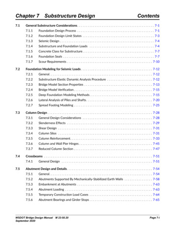
3. Figures41.341.3Y7.19.522.29.5YX123.8XXX28.261.912 GA.5Y819-15075 8.141.37.19.519-150YYS2SR2875 O.C.S2BBSWSR1BBSWSR2BBSWFigure 1A – Sasco Channels (Metric)Sasco Seismic Restraint ManualThe informationin thisinmanualis subject toJonestoChristoffersenLtd.’sstructural engineeringfoundEngineeringon page 1 of thisDisclaimermanual.Theinformationthis manualis ReadsubjectRead n Page 1 of this Manual18
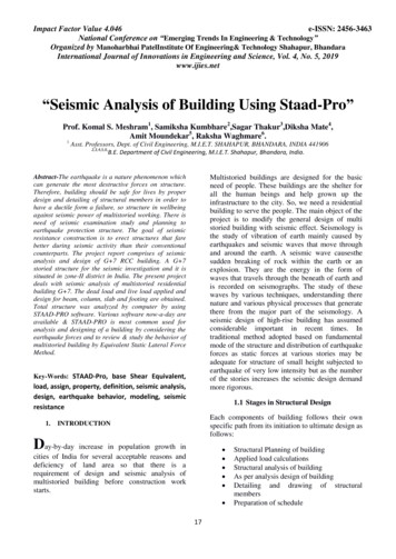
158"15"83"8Y3"8XX478"0.105" (12 GA.)Y1.110"XX0.105" (12 815"8YXXYYYS1SR13/163/4"-6"5/163/163" O.C.3/4"-6"5/163" BBSW15"8SR1BBSW3"815Y"83"8YXYX1"34932"15 "80.105" (12 GA.)XXX1"340.714"X0.714"15 "80.105" (12 GA.)XX3/163/4"-6"YYS2SR2Y3" " O.C.S2BBSWSR1BBSWFigure 1B – Sasco Channels (Imperial)Sasco Seismic Restraint ManualThe informationin thisinmanualis subject toJonestoChristoffersenLtd.’sstructural engineeringfoundEngineeringon page 1 of thisDisclaimermanual.Theinformationthis manualis ReadsubjectRead n Page 1 of this Manual19
1/ 2" Ø BOLT ANDSR12,CLAMPING NUT S12,TYPICAL.HANGER RODSASCO SR2S2LONGITUDINALBRACEHANGER RODSTIFFENER.SEE FIGURE 6SASCO SR2S2TRANSVERSEBRACE(45 MAX.)(45 MAX.)SASCO SEISMICHINGE, S293A-EG.SR293A-EGTRAPEZESASCO SEISMICSR292A-EGHINGE, S292A-EG.SPAN LENGTHSEE FIGURE 3ASEE FIGURE SR293A-EGS293A-EG EXCEEDSSR292A-EGLOAD2R292A-EGEXCEEDS THETHE NUT(S).Figure 2 – Typical Trapeze with Transverse and Longitudinal Braces1/ 2" Ø BOLT AND CLAMPINGNUT(S) S12,SR12,TYPICAL.TYPICALPbtProd t / Trod t(45 MAX.)VptSASCO SEISMICHINGE, SR293A-EGS293A-EG.PbProd / TrodWp(45 MAX.)VpSASCO SEISMICHINGE, THETHEPULLOUTPULLOUTLOAD CAPACITYCAPACITYOFOFSR292A-EGS292A-EG ANDAND SR293A-EGS293A-EG EXCEEDSANDOFOFTHEBOLT(S)ANDCLAMPINGNUT(S)AND UT(S).(A)(A) TransverseTransverse(B)(B) LongitudinalLongitudinalFigure 3 – Typical Trapeze and Brace DetailsSasco Seismic Restrain
Sasco Seismic Restraint Manual The information in this manual is subject to Read Jones Christoffersen Ltd.’s structural engineering disclaimer found on page 1 of this manual. 5 Seismic Design Information The following defines the design late