Transcription
Digital Avionics:A Computing PerspectiveElisabeth A. StrunkJohn C. Knight(Eds.) IEEE, Elisabeth A. Strunk, John C. Knight
IEEE, Elisabeth A. Strunk, John C. Knight
PrefaceThis is a book about the use of computers in airplanes. It is intended primarily for people with acomputer science background who would like to learn more about this computer-dependent applicationdomain. It can also be useful for novices from other disciplines who would like an introduction to thedomain, in order to understand the ideas and vocabulary associated with it. The book is suitable for a finalyear undergraduate course or a first-year graduate course in avionics systems, or as a reference for anengineer entering the avionics field.The term avionics is a contraction of aviation electronics, and digital avionics is that part of theavionics field concerned with digital, usually computerized, technology. This is an important field becausemodern aircraft use digital avionics extensively for a wide variety of applications. Modern autopilots, forexample, are very sophisticated devices capable of reducing pilot workload dramatically. With a few rareexceptions, autopilots are completely computerized.In practice, most cockpit functions are computerized. This is the result of a transition that has occurredin recent years in which older, electro-mechanical technology has been replaced by technology from thecomputer age. Displays in aircraft cockpits used to be mostly mechanical dials and mechanical graphics.These mechanical systems are being replaced quickly by what are referred to as glass cockpits in whichdisplays are presented on monitors similar to those found on personal computers.The impact of computer technology extends beyond cockpit displays; the term avionics also applies tothe use of computers in the aircraft structure. In older aircraft, control of the engines and the controlsurfaces (e.g., the flaps and rudder) was achieved with mechanical and hydraulic links. The constructioncosts, maintenance costs, and operational weight of all the different mechanical elements made themtargets for replacement with digital technology, and that led to the introduction of fly-by-wire control. Theterm fly-by-wire usually refers to the combination of the communication of control signals over a digitaldata bus and the use of those signals by computers within the aircraft structure for adjustment of thecontrol surfaces and the engine settings.As airplanes have thus become flying computer systems, avionics has assumed an increasinglysignificant role in their development and production. Construction of avionics systems requires large teamsof engineers from a wide variety of disciplines, including computer engineering and software engineering.It is impossible for all those engineers to be familiar with the system’s complex goals and operatingprinciples. Still, it would be helpful if they all understood generally what avionics systems are for and howthey work. It is with that in mind that the editors and authors produced this book.We have organized this book into three parts. The first provides background material on aircraft andair traffic that is necessary to understand the requirements of the computing systems discussed in the book.The second part describes a spectrum of avionics components, discussing their specific requirements andi
design concerns. The third part looks at general dependability issues in avionics, from both the computerengineering and the human-computer interaction perspectives.Although we edited the book, most of the material was written by students in a graduate seminar ondigital avionics that we taught in the Spring of 2004. We are very grateful to the participants in the coursefor both their work in the course and their production of the material for this text. Their names appear withthe chapters that they wrote. Dean Bushey also contributed material, although he did not attend the course.Finally, as well as being an author, Tony Aiello was very helpful in preparing this book. We are verygrateful to all of the authors for their efforts.Elisabeth StrunkJohn KnightCharlottesville, VA 2006avionics@cs.virginia.eduDependability Research GroupDept. of Computer ScienceUniversity of Virginiaii
AuthorsM. Anthony AielloMaster of Computer ScienceUniversity of VirginiaAugust 2005William S. GreenwellMaster of Science, Computer ScienceUniversity of VirginiaMay 20032nd Lt. J. Graham AlsbrooksMaster of Science, Mechanical EngineeringUniversity of VirginiaMay 2005Kathryn A. KleinMaster of Science, Systems EngineeringUniversity of VirginiaAugust 2005Matthew BoltonMaster of Science, Systems EngineeringUniversity of VirginiaMay 2005John C. KnightDoctor of Philosophy, Computer ScienceUniversity of Newcastle Upon TyneMay 1973Lt. Col. Dean E. BusheyMaster of Science, Computer ScienceClemson UniversityDecember 1996Lori StotlerMaster of Computer ScienceUniversity of VirginiaMay 2004Maj. John C. GiordanoMaster of Computer ScienceUniversity of VirginiaMay 2004Master of Public AdministrationTroy State University1999Elisabeth A. StrunkDoctor of Philosophy, Computer ScienceUniversity of VirginiaMay 2005Sinem C. GöknurMaster of Science, Systems EngineeringUniversity of VirginiaAugust 2005Rajat TikooMaster of Computer ScienceUniversity of VirginiaAugust 2004Sarah WaziruddinMaster of Computer ScienceUniversity of VirginiaMay 2004iii
iv
Table of ContentsAircraft Dynamics and the National Airspace SystemChapter 1. Basic Aircraft Dynamics .11. The Four Forces and Basic Aerodynamics .11.1. Airfoils and Fluid Dynamics .11.2. Lift.31.3. Weight and Load .31.4. Thrust .41.5. Drag .42. Aircraft Orientation.53. Aircraft Stability .54. Control Surfaces .7Chapter 2. The National Airspace System and Air Traffic Control .111. Types of Airspace .112. Controllers and Facilities .123. Flight Plans .124. VFR and IFR Landing .135. Looking Ahead .13Chapter 3. Navigation.151. Coordinate Frames .152. Navigation Systems .162.1. Positioning Systems .162.2. Dead-Reckoning Navigation Systems .193. Current Practice in Navigation .203.1. Navigation System Characterization .203.2. Navigation Software .203.3. Design Tradeoffs .213.4. System Profiles.214. Communications, Navigation, and Surveillance / Air Traffic Management .214.1. CNS/ATM Implementations .244.2. The Future of CNS/ATM .255. Closing Comments.25Avionics ComponentsChapter 4. Flight Control Systems.291. Flight Control Background .291.1. Traditional Flight Control Systems .291.2. Digital Flight Control Systems .31 IEEE, Elisabeth A. Strunk, John C. Knightv
1.3. FCS Architecture .351.4. Flight Control Laws.361.5. Looking Ahead .362. Survey of Fly-by-Wire Flight Control Systems .372.1. Airbus A320 .372.2. Boeing 777 .403. Flight Control Design Philosophy .42Chapter 5. Autopilot Flight Director Systems.451. AFDS Components .452. Modes.463. Mode Confusion .494. Conclusion .51Chapter 6. Flight Management Systems .531. Short History of Flight Management Systems .531.1. Origins of the Flight Management System .531.2. Development of the Flight Management System .542. Main Functions of the FMS.543. FMS Components .563.1. Flight Management Computer System .563.2. Electronic Flight Instrument System.573.3. Component Interactions.593.4. Brown vs. Gray FMS Systems .594. Conclusion .60Chapter 7. Mission Specific Avionics .631. Functional Requirements – Influence on Design.631.1. The UH-60 and MH-60 Variant.631.2. The C-130 and AC-130 Variant .642. Special Requirements for Special Operations .653. Common Airframes for Dissimilar Needs .66Digital Avionics DependabilityChapter 8. Human Centered Design .731. Background .741.1. Current Design Practice .741.2. Cognitive Considerations .751.3. Considerations of Human Error .761.4. Human-Centered Flight-deck Design and Philosophy .792. Example Systems.792.1. Displays and Information Automation.792.2. Advanced Display Technology.822.3. Automated Pilot Assistants .83Chapter 9. Dependability in Avionics Systems .871. Dependability .87vi IEEE, Elisabeth A. Strunk, John C. Knight
2. Faults.882.1. Types of Faults .882.2. Dealing With Faults .882.3. Electromagnetic Interference .893. Major Computing Elements and Architectures .904. Dependability in Avionics Hardware .915. Bus Architectures.925.1. Terminology .925.2. Time-triggered Versus Event-triggered Buses .925.3. Data Bus Dependability .936. Software Systems.946.1. The Software Lifecycle .956.2. Aviation Standards and Regulations Governing Software .966.3. Tools and Techniques for Avionics Software Construction .977. System Failures .99Annotated Bibliography .103List of Acronyms.117Glossary .121 IEEE, Elisabeth A. Strunk, John C. Knightvii
viii IEEE, Elisabeth A. Strunk, John C. Knight
Part IAircraft Dynamics andthe National Airspace System IEEE, Elisabeth A. Strunk, John C. Knightix
x IEEE, Elisabeth A. Strunk, John C. Knight
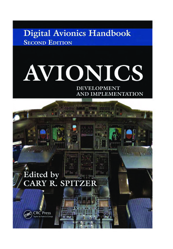
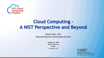
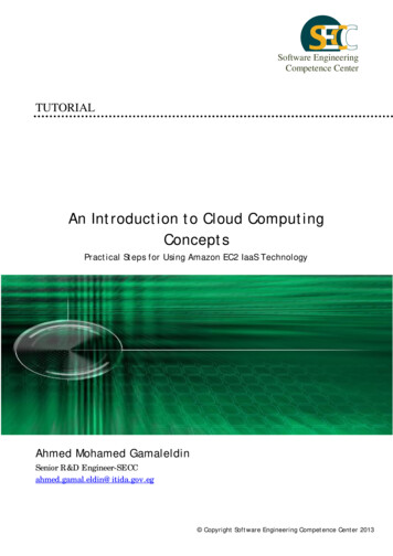
CHAP TER 1Basic Aircraft DynamicsDean E. BusheyElisabeth A. StrunkAvionics systems can control many aspects of aircraft operation, but one of their main responsibilitiesis looking after the basic movement and integrity of the aircraft. The control algorithms used for this purpose can be very complex for any type of aircraft, and they are very different from those that people whodrive cars, but do not pilot aircraft, are accustomed to. The control algorithms involve various concepts anddefinitions that are equally unfamiliar.We begin our discussion of avionics, therefore, with a brief overview of the physical characteristics offlight and the terminology that surrounds them. We also describe various essential elements of an aircraft'smechanical system. These algorithms, characteristics, terms, and mechanical elements are important toavionics system developers because of their role in defining what the avionics system has to do and how itmust behave.1.The Four Forces and Basic AerodynamicsAircraft motion during flight is caused by four forces that operate on the vehicle. The forces, illustrated inFigure 1, are: Thrust: The force exerted by the engine orpropeller, which pushes air backwards withthe object of causing a reaction, or thrust, ofthe airplane in the forward direction. Drag: The resistance of the airplane to forward motion; the force acts directly oppositeto thrust. Lift: The upward force created by the wingsmoving through the air, which sustains theairplane in flight. Weight: The downward force due to theweight of the airplane and its load.LiftDragThrustWeightFigure 1. Thrust, Drag, Lift, and Weight1.1.Airfoils and Fluid DynamicsThese basic four forces combine to give an overall picture of what is happening to an aircraft as it movesthrough air. The debate over what generates the lift on an airfoil has been going on for decades. There aretwo prevalent theories. One is the Bernoulli effect, which explains lift through the increase in speed over IEEE, Elisabeth A. Strunk, John C. Knight1
Figure 2. Depiction of the Bernoulli effect[1]the top of the wing. The other is the Coanda effect, which explains lift using the change in direction ofwind over an airfoil.Daniel Bernoulli (1700-1782) was a Swiss mathematician and physicist who studied fluid dynamicsand fluid interactions. He discovered that as fluid increases in velocity there is a corresponding decrease inpressure around the area of increased speed. Applying Newton’s laws of the conservation of energy hecame up with the basic law of fluids, which says that the sum of the kinetic energy, potential energy andstatic pressure of freely flowing fluid always remains constant. The mathematical formula that governsfluid (air) flow in and around objects is shown in Figure 2.The next step is looking at the airflowover an airfoil (such as a wing). Figure 3shows a cross-sectional view of airflow particles flowing over a wing. The particles in theairflow are traveling at the same speed as theyapproach the wing, as depicted by the firstcolumn. As the flow approaches the wing, thecamber, or shape of the wing, changes thepattern of the airflow. As shown in the lasttwo columns, the air flowing over the top ofthe wing actually travels faster than the airover the bottom of the wing.Applying Bernoulli’s theorems to thisshows that a lower pressure region is createdon top of the wing, relative to the bottom ofFigure 3. Aerodynamic Forces on a Wing [2]the wing, and the wing is pulled upward bythe difference in pressure. Increasing theangle at which the wing intersects the airflow increases the difference between the air speed over the top ofthe wing and the air speed over the bottom of the wing. This angle is called the angle of attack or angle ofincidence, and is usually represented in calculations by the character α. It is used to alter the amount of lift2 IEEE, Elisabeth A. Strunk, John C. Knight
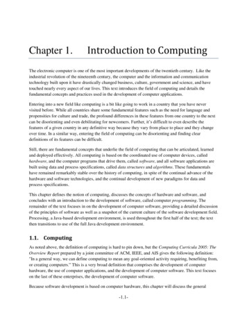
generated by the wing. Lift is also generated on the fuselage due to its similar shape. Here we discuss onlythe wings, but similar principles hold for the fuselage.An alternate view of the lift created by airflow over awing is that the change in direction, or downwash, atthe trailing edge of an airfoil is what creates lift.Applying Newton’s third law, the force of the downwash causes an equal but opposite force in the upwarddirection on the wing. The governing principle is theCoanda effect, which states that fluids tend to followFigure 4. Airflow Over a Wing[2]the shape of a curved surface.Whichever theory you follow, the lifting properties of a wing are directly related to the ability of thatwing to change the flow of air as it passes over the wing. An airfoil does not have to be curved on the topand/or flat on the bottom in order to work. As long as the airflow is changed, and thus the speed of the airis changed, the airfoil will produce lift. A rounded leading edge helps, but even a barn door will fly, givena positive angle of attack into the windstream.1.2.LiftAs described in the previous section, lift is generated by the movement of the air around and over thewings, and other surfaces of the aircraft. According to Bernoulli’s theory, the air moving over the top of apositively cambered wing must travel faster than air moving along the bottom edge of the wing. This creates low pressure on top of the wing relative to the bottom. This generates a lifting force, and can be mathematically modeled by the following equation:C L is the lift coefficient of the wingLift C L x 1/2 ρV x S2where1/2ρV 2 represents the dynamic pressure of the airflowρ air densityV aircraft velocityS wing areaThus to generate greater lift you can: (1) increase the angle of attack (up to a point which will be discussedlater); (2) fly faster to increase velocity; (3) move to an area of greater air density; or (4) have greater wingsurface area that is in the airstream.The longitudinal shape, or camber, of the airfoil has a major impact on its aerodynamic characteristics.The more curved the upper surface of the wing, the lower the pressure above it. The curve of the wing isfixed for the most part (the control surfaces that constitute the exceptions to this are mentioned below). Thepressure difference can be adjusted, however, by varying the angle of attack as the airfoil hits the windstream.Figure 5(a) shows the typical C L vs. angle of attack curve for light airplanes. Lift increases in directrelationship to the increase in angle of attack until a maximum angle, called the Critical Angle of Attack, isreached. Lift then decreases rapidly. This represents the onset of aerodynamic stall. A wing stalls at a predetermined angle of attack: this angle is manufactured into the wing and does not change. Figure 5(b)shows the induced drag factor that corresponds to the lift factor generated.1.3.Weight and LoadWeight is the downward force of gravity that acts opposite to lift. It is measured at the aircraft’s center ofgravity; the center of gravity is usually positioned in front of the aerodynamic center for stability (see Section 3). In addition to the basic weight of an aircraft, additional forces are induced when an aircraft changesits plane of motion. These are the forces that make you feel heavier when an aircraft accelerates, banks, or IEEE, Elisabeth A. Strunk, John C. Knight3
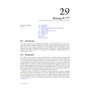
CL(a)CD(b)Legend:α: Angle of AttackC L: Coefficient of LiftCriticalAngle ofAttackCriticalAngle ofAttackC D: Coefficient of DragααFigure 5. Graph of Angle of Attack vs. Coefficient of Lift and Coefficient of Drag[3]begins a climb or descent. These are termed aerodynamic loads, and usually expressed as a load factor.The load factor is the magnitude of the load divided by the aircraft’s weight, and is measured in g’s, ormultiples of the aircraft’s weight.1.4.ThrustThrust is the force created by the aircraft’s engines that moves the aircraft forward. Thrust is measured as avector beginning at the aircraft’s aerodynamic center, pointing along the aircraft’s heading, and orthogonalto the lift and weight vectors. Because it is orthogonal to these vectors, it is not necessarily parallel to theaircraft’s fuselage. Increasing the angle of attack requires a corresponding increase in thrust to keep the aircraft’s speed (ground speed or airspeed) constant.1.5.DragThere are two principal types of drag associated with an aircraft moving through air: Friction, or parasitic drag: This occurs as the aircraft is moving through the air, and is the “rubbing” resistance of the aircraft to the air throughwhich it moves. This factor increases by thesquare of the speed through the air.Induced drag: This is drag induced due to thelifting force created by the airfoils (e.g., wings). Itis the result of the wing’s work in sustaining theairplane in flight, and is a function of the speed ofthe aircraft, coefficient of drag, and the density ofthe air.Total DragDrag Parasite andInterferenceDragInduced DragSpeedFigure 6 shows how drag is related to speed. TheFigure 6. Drag and Speed [4]point where total drag is lowest is called Lift overDrag maximum, or L/D max. Below this point thepredominant factor in total drag is induced drag, andabove this point the predominant factor in total drag is parasitic drag. Airspeeds below L/D max are an areaknown as the region of reverse command—that is, the slower you go, the more thrust you must add toovercome the drag.Two other types of drag that interact with an aircraft in flight are worth noting. Wave drag is drag thatcomes into play as an aircraft approaches the speed of sound, or Mach speed. As the aircraft approaches thespeed of sound, shock waves start to build up, generally starting around 0.75 Mach. Bernoulli’s rules no4 IEEE, Elisabeth A. Strunk, John C. Knight
longer apply when aircraft velocity passes 1.3 Mach. The very nature of lift changes, accompanied by acorresponding change in the drag relationships. The other type of drag that influences flight is called forminterference drag, and is due to the shape and smoothness of the aircraft.2.Aircraft OrientationExplaining an aircraft’s aerodynamic characteristics requires clarification of the terminology used to referto the aircraft’s orientation in 3-dimensional space. The orientation is described using rotation about threeaxes, whose origins are at the center of gravity of the aircraft. The labels for the 3 axes of the aircraft,shown in Figure 7, are: Pitch: the axis roughly parallel to the wingsof the aircraft. Movement about the pitchaxis results in up and down movement of thenose. Pitch angle is sometimes measured asthe angle of attack, which is angle betweenthe wings’ chord line and the relative wind.Roll: the axis from the nose to the tail of theaircraft. Movement about the roll axis leavesthe nose steady but moves the wings up anddown. The angle of roll is called the bankangle.YawPitchRollYaw: the axis that runs vertically throughthe aircraft. Movement about the yaw axiscauses the nose to move left and right. Theangle of yaw is called the slip angle.Figure 7. Aircraft MotionAn aircraft’s attitude is its orientation to the horizon, a combination of the angle of attack and the bankangle. An aircraft is trimmed if its angle of attack and its bank angle are both 0.3.Aircraft StabilityAircraft control is heavily dependent on an aircraft’s stability characteristics. Stability is the quality ofreturning to an original angle of attack, slip, or bank after a disturbance from an equilibrium. The three aircraft axes have corresponding terms to describe their stability: Longitudinal stability: stability in pitch; Lateral stability: stability in roll; Directional stability: stability in yaw.Another aspect of aircraft stability is the static vs. dynamic characteristics of an airplane. Static stability is the quality of initially moving towards a trimmed state immediately after a disturbance. Figure 8illustrates the conditions of static stability using a ball on various types of surfaces as an analogy. In the(a) Statically Stable(b) Statically Unstable(c) Neutral StabilityFigure 8. Conditions of Static Stability IEEE, Elisabeth A. Strunk, John C. Knight5
statically stable case (a), the ball will initially attempt to return to its equilibrium position when disturbed;just as statically stable aircraft exhibit similar behavior when disturbed in the pitch, roll, or yaw axes. In thestatically unstable case (b), the ball will tend to move away from its equilibrium position when disturbed asis the case with statically unstable aircraft. Statically neutral aircraft exhibit no tendency toward or awayfrom equilibrium when disturbed as illustrated in case (c).Dynamic stability refers to the nature of the oscillations an aircraft exhibits once it is disturbed fromequilibrium. Dynamically stable aircraft exhibit damped oscillations, meaning that the oscillations lessenin amplitude over time and converge on stable flight. Thus, dynamically stable aircraft are necessarily statically stable. Static stability about an axis does not, however, imply dynamic stabil
The term avionics is a contraction of aviation electronics, and digital avionics is that part of the avionics field concerned with digital, usually computerized, technology. This is an important field because modern aircraft use digital avionics extensively f