Transcription
SeismicConstructionHandbook
Seismic Construction HandbookIntroductionScopeThis document is intended to help the reader understand the seismic construction requirements for lay-in,suspended ceilings. It explains those requirements anddemonstrates generally accepted construction methodsthat comply with these requirements. It also includes acomprehensive list of documents containing these requirements. It will list what suspended ceiling systems arecovered by the IBC/ASCE 7 prescriptive requirements andwhich are not. Finally, it will give tips to reduce construction costs and suggestions to solve commonly encountered problems.Building CodesMost people are aware that nearly all construction inthe United States is governed by building codes.Most building code requirements arise from two concerns: Life Safety and Aesthetics. Examples of life safetyconcerns are fire safety, earthquake, wind and structuralrequirements. Examples of aesthetic concerns are fencing and usage codes (commercial, industrial, residential),as well as signage requirements. It is important to understand that most codes are written “after the fact.” Thatis, life safety codes are written or updated after a failure.Aesthetic codes are written or updated after residentscomplain to local government. Although code requirements seem arbitrary, they are almost always rooted inpast problems. Anyone from California or Florida is familiar with changes in code requirements after natural disasters like earthquakes or hurricanes.Code prioritization, that is, which document controlsthe construction in question, is likewise poorly understood. The IBC and ASCE 7 are described as “modelcodes.” They do not have the force of law unless adoptedby governments. In most states this occurs at the statelevel. The state code is then adopted by local jurisdiction. Some states do not have a state-level building codeso all adoption is at the local level. Both the state andlocal jurisdictions can and do make changes to the codes.Thus, the only way to know the exact requirements isto know what is required by the governmental agencyhaving jurisdiction. Additionally, many states have separate bodies responsible for schools, hospitals, prisons,state-owned construction, etc. It is the responsibility of2CISCA Seismic Construction Handbookthe design professional of record to determine the actualrequirements for each construction project.Because of several agencies “adopting” other standards as part of their own, the prioritization for seismicconstruction of suspended ceilings is particularly complex.The hierarchy from lowest to highest is as follows: ASTM E580 ASCE 7 (which adopts ASTM E580 for most ofits seismic requirements for suspended ceilings) IBC (which adopts ASCE 7 for nearly allseismic requirements) State Building Code Local Jurisdiction (city, county, township, orstate agency such as (OSHPD))The local jurisdiction has the final say for all coderequirements. Thus, the City of Los Angeles has requirements different from the state of California and the stateof Oregon has different requirements from the IBC. It isgenerally only possible to know all the requirements at thelocal level by doing business in that jurisdiction.Although this priority may seem backwards, it is actually the most practical way of administering code enforcement. The model codes cannot possibly anticipate therequirements of every jurisdiction. Jurisdictions withunique natural hazards, such as Florida (hurricanes) orHawaii (active volcanoes), will be much more qualified tomake specific code requirements for these conditions.Agencies responsible for specialized use construction,such as OSHPD (hospitals), will have a better understanding of the requirements of these facilities. Furthermore,construction details often make compliance with specificcode requirements impractical. Local officials and inspectors need the authority to approve alternate constructiondetails to avoid needlessly costly rework.The prescriptive requirements in ASCE 7 are intendedto cover direct-hung acoustical panel and lay-in panelceiling systems.The following suspended ceilings are exempted fromthe suspended ceiling requirements of the ASCE 7 asdefined by ASTM E580. Screw or nail attached gypsum board ceilingsof one level, surrounded by walls that connectto the building structure
Ceilings less than 144 square feet (13.4 m2) thatare surrounded by walls that connect to thestructure above. Island ceilings (suspended from chainsASTM E580)The following ceilings require custom solutions as theyare not exempt, but cannot be constructed by using theprescribed construction method. Indirect-Hung Ceilings Curved Ceilings Lath and Plaster CeilingsChanges in suspended ceiling systemsASCE 7-10 from ASCE 7-05 ASTM E580 is specified in ASCE 7-10 instead ofthe two previous CISCA Standards Much of the specification in ASCE 7-05 has beeneliminated as it is also contained in ASTM E580 These two changes make determining therequirements much simpler, as virtually allrequirements are contained in E580, instead ofspread out over ASCE 7 and two CISCA documents When dividing a very large ceiling into 2,500square feet (230 m2) such as using seismicseparation joints or other means, the aspect ratiois now limited. The ratio of the longest dimensionto the shortest must be less than or equal tofour Power actuated fasteners are now permitted tobe used for loads not greater than 90 lbs. (400 N)in concrete and not greater than 250 lbs. (1000 N)in steel. This makes them suitable for suspensionwires, but not for lateral bracing. Lateral bracingconnections must be capable of holding at least250 lbs. (1000 N). This is the equivalent of the180 pound (800 N.) connection force at 45degrees. Lath and Plaster ceilings are no longerexempt and will require custom solutionsSeismic Design CategoryThe requirements for a suspended ceiling are determinedby the buildings Seismic Design Category. Determinationof the Seismic Design Category is complex and mustbe determined by a Registered Architect or ProfessionalEngineer and should be found in the construction documentation.The Seismic Design Category is determined from thefollowing parameters: The design force of the earthquake, which isdetermined by the location of the building withrelationship to known earthquake faults The soil the building foundation rests on The Occupancy Category (use of the building)Seismic Design Categories are given letter classificationsA, B, C, D, E, and F. The following table lists the requirements for suspended ceilings.Categories A & BNo RequirementsCategory CIsland Ceilings Described inSeismic Design Category CCategories D, E, & FBraced Ceiling Described inSeismic Design Category D, E,&FCIS CISCA Seismic Construction Handbook3
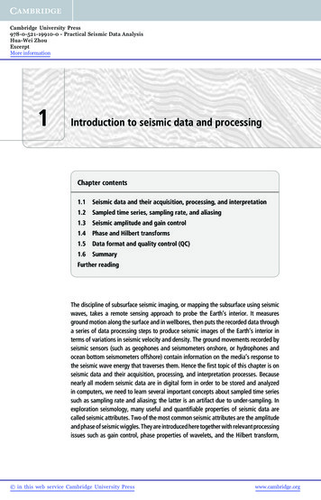
Seismic DesignCategory C— Design IntentDamage has been observed in moderate earthquakes to suspendedacoustical tile ceilings. Failure typicallyoccurs at the perimeter of the ceiling. Unbraced ceilings are significantlymore flexible than the floors or roofsto which they are attached. The ceilings therefore will sway independentfrom the floor or roof, typically resulting in the runners at the walls breakingtheir connections. This constructionmethod is designed to avoid this typeof damage when the anticipated earthquake movements are small. The ceiling is isolated from the perimeter sono forces will be transferred from thewalls to the suspended ceiling. Thus,the building is free to move withoutcontacting the ceiling. The verticalhanger wires will transfer very littleforce or movement from the supporting structure to the suspended ceiling.Thus, the ceiling will not experienceany significant forces. For this methodto function, no other attachments thatmay transfer force to the ceiling canbe made. Structural components suchas columns must be isolated from thesuspended ceiling similar to the surrounding walls. Other non-structuralcomponents such as ceiling-heightpartitions, sprinklers, etc., must also beisolated from the suspended ceiling.IBC 2012SEISMIC DESIGN CATEGORY CCodeSectionASCE 7-10. Section 13.5.6.2.1ASTMC635DutyRatingIntermediate or Heavy Duty Load Rating grid asdefined by ASTM C635Minimum main runner splices and cross runner intersectionsGridConnections strength of 60 lbs. (270 N)VerticalVertical hanger wires must be a minimum No. 12 gageSuspensionWiresVertical hanger wires maximum 4 feet (1200 mm.) on centerunless justified by calculations or test resultsFor field tied connections, vertical hanger wires must besharply bent and wrapped with three turns in 3 inches (75mm) or less (Figure 1)All vertical hanger wires may not be more than 1/6 out ofplumb without having additional wires counter splayedWires may not attach to or bend around interfering equipment.Use trapezes to avoid such obstacles. (Figure 2)LateralForceBracingPerimeterLateral force bracing is not permittedPerimeter closure (molding) width must be a minimum of 7/8inchA minimum clearance of 3/8 inch (9.5 mm) must be maintained on all, four sides (Figure 3)Grid ends on all four walls must be free to moveWhen a closure angle with a supporting shelf less than 7/8inch is used, perimeter runners must be supported by verticalhanger wires not more than 8 inches from the wallProprietary solutions may utilize approved attachment devices on some walls and varying closure widthsPerimeter runner ends must be tied together to preventspreading (Figure 3 at right)4CISCA Seismic Construction Handbook
5— Technical Illustrations Not To Scale —Figure 1Figure 2Figure 3CISCA Seismic Construction Handbook5
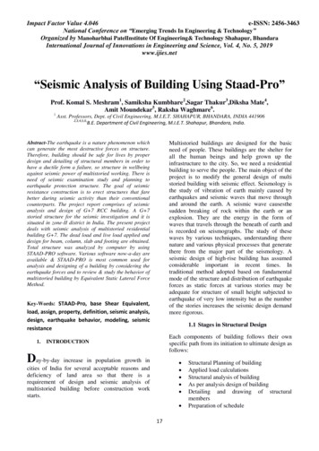
Common Problems andSuggested SolutionsTemporary Installation ConnectionsIt is often difficult to install the ceilingwithout any perimeter restraint. Temporary connections at the perimeter maybe used as long as they are removedwhen construction is complete.IBC 2012SEISMIC DESIGN CATEGORY CLightFixturesSurface mounted lighting fixtures shall be positivelyclamped to the grid (Figure 4 at right)Clamping devices for surface mounted lighting fixturesshall have safety wires to the suspension system or thestructure aboveIsland Ceilings - ASCE 7-10, Section13.5.1 and ASTM E580 1.8 exemptisland ceilings from compliance withseismic requirements with the followinglanguage:Lighting fixtures and attachments weighing 10 lbs. (4.5kg.) or less (e.g. canister light fixtures) require one No. 12gage (minimum) hanger wire connected from the housingto the structure above. This wire may be slack.EXCEPTION: Components supportedby chains or otherwise suspendedfrom the structure are not required tosatisfy the seismic force and relativedisplacement requirements providedthey meet all of the following criteria:1. The design load for such itemsshall be equal to 1.4 times the operating weight acting down with asimultaneous horizontal load equalto 1.4 times the operating weight.The horizontal load shall be appliedin the direction that results in themost critical loading for design.2. Seismic interaction effects shallbe considered in accordance withSection 13.2.33. The connection to the structureshall allow a 360 range of motion inthe horizontal planeBut ASCE 7 also states in section13.2.3:The functional and physical interrelationship of components, theirsupports, and their effect on eachother shall be considered so that thefailure of an essential or nonessentialarchitectural, mechanical, or electrical component shall not cause thefailure of an essential architectural,mechanical, or electrical component.This must also be considered withisland ceilings.6CISCA Seismic Construction HandbookLighting fixtures must be positively attached to the grid byat least two connections, each capable of supporting theweight of the lighting fixture (National Electrical Code)Lighting fixtures weighing greater than 10 lbs. (4.5 kg.) butless than 56 lbs. (25.5 kg) require two No. 12 gage (minimum) hanger wires connected from the fixture housing tothe structure above. These wires may be slack.Lighting fixtures weighing 56 lbs. (25.5 kg ) or more require independent support from the structure above byapproved hangersPendent-hung light fixtures shall be supported by aminimum one No. 9 gage wire or other approved alternatesupportRigid conduit is not permitted for the attachment of fixturesMechanicalServicesFlexibly mounted mechanical services weighing less thanor equal to 20 lbs. (9 kg) must be positively attached tomain runners or cross runners with the same load carrying capacity as the main runnersFlexibly mounted mechanical services weighing morethan 20 lbs. (9 kg.) but less than 56 lbs. (25.5 kg) requiretwo No. 12 gage (minimum) hanger wires. These wiresmay be slack.Flexibly mounted mechanical services 56 lbs. or greaterrequire direct support from the structureSpecialConsiderationAll ceiling penetrations must have a minimum of 3/8 inch(9.5 mm) clearance on all sides. (Figure 5 at right)PartitionsThe ceiling may not provide lateral support to partitionsPartitions attached to the ceiling must use flexible connections to avoid transferring force to the ceilingExceptionsThe ceiling weight must be 2.5 lbs. / square foot (12.2 kg./square meter) or less. For ceilings over 2.5 lbs. / squarefoot (12.2 kg. /square meter) the prescribed constructionfor Seismic Design Categories D, E, and F must be used.
— Technical Illustrations Not To Scale —Figure 4Figure 5Minimum 3/8” (10mm)CISCA Seismic Construction Handbook7
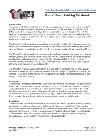
Seismic DesignCategories D, E, & F— Design IntentFor the majority of buildings, the nonstructural components represent a highpercentage of the total capital investment.Failure of these components in an earthquake can disrupt the function of a building as surely as structural damage, andcan pose a significant safety risk to building occupants as well. Past earthquakeshave dramatically illustrated the vulnerabilities of the nonstructural components.Apart from the falling hazard posed by thelight fixtures, non-structural failures cancreate debris that can block egress fromthe building, and hamper rescue efforts.The basic objective of seismic design isto provide an adequate level of safety,supplying protection that is appropriatefor the seismic hazard and the importanceof the component or system.Beyond this basic level of safety,which protects occupants from lifethreatening injury or death, higher levelsof performance may be demanded to limitdamage or protect against loss of function. Essential facilities, such as hospitals,police and fire stations, and emergencycommand centers may be designed withthe intent that they meet the immediateoccupancy or operational performanceobjectives. Structures designed to theseperformance objectives are expected tobe functional during or after an earthquake. Prevention of panic is also animportant goal. When ceiling components fall from the ceiling, inhabitantshave been known to flee in panic, even ifthe building structure is not in danger ofcollapse. There are numerous instancesof panic causing injuries and deaths whenno physical danger was actually present.A common failure observed in a moderate earthquake occurs to suspendedacoustical tile ceilings. Failure typicallyoccurs at the perimeter of the ceiling.The prescribed construction of SeismicDesign Categories D, E, & F, is designedto tie the suspended ceiling system tothe structure so that all seismic forces aretransferred and dissipated through thebuilding structure. Vertical compressionposts are also required at the location ofthe diagonal wires to resist the upwardcomponent of force caused by the lateralloads.8CISCA Seismic Construction HandbookIBC 2012SEISMIC DESIGN CATEGORY D, E, & FCodeSectionASCE 7-10. Sections 13.5.6, 13.5.6.2 and 13.5.6.2.2ASTMC635Duty RatingHeavy Duty Load Rating as defined in ASTM C635is requiredGridConnectionsMinimum main runner splices and cross runner intersections strength of 180 lbs. (801 N)VerticalSuspensionWiresVertical hanger wire must be a minimum No. 12 gageVertical hanger wires maximum 4 feet (1200 mm.) oncenter unless other design approvals are listed by themanufacturerVertical hanger wires must be straight and shall not usebends or localized kinks for leveling the systemFor field-tied connections, vertical hanger wires must besharply bent and wrapped with three turns in 3 inches(75 mm) or less. (Figure 1)All vertical hanger wires may not be more than 1/6 out ofplumb without having additional wires counter splayed(Figure 6)A device used to secure the hanger wire to the structureabove must sustain a minimum load of 90lbs (40 kg.)Power actuated fasteners are now permitted to be usedfor loads that do not exceed 90 lbs. (40 kg.) in concreteand do not exceed 250 lbs. (110 kg.) in steelWires may not attach to or bend around interfering equipment.Use trapezes to avoid such obstacles( Figure 2)LateralForceBracingLateral force bracing is required for all ceilings greaterthan 1000 square feet (90 m2)Where required, lateral force bracing (splay wires or rigidbracing and a compression post) must be located within 2inches (50 mm) of the main runner / cross runner intersection and splayed approximately 90 apart in the plan view,at a maximum 45 angle from the horizontal and located12 feet (3600 mm) on center in both directions, starting 6feet (1800 mm) from two adjacent walls (Figure 7)Lateral force bracing must be spaced a minimum of 6inches (150 mm) from unbraced horizontal piping or ductworkLateral force bracing connection strength must be a minimum of 250 lbs. (110 kg.)Rigid bracing must be designed to limit deflection to lessthan ¼ inch (6.5 mm)
— Technical Illustrations Not To Scale —Method 1 - Countersplay In-Vertical-Plane of the Main Runner with CommonPoint at Building StructureFigure 6Method 2 - Countersplay In-Vertical-Plane of the Main Runner withCommon Point at Main RunnerMethod 3 - Countersplay Out-ofVertical-Plane of the Main RunnerFigure 7CISCA Seismic Construction Handbook9
CommentsIBC 2012SEISMIC DESIGN CATEGORY D, E, & FHeavy Duty GridThe Duty Classification of a HeavyDuty grid system is defined by ASTMC635 as main runners that can sustaina load of 16 lbs. /foot (24 kg / m) with adeflection of less than or equal to .133”(3.4 mm) (L/360) over a 48 inch (1200mm) hanger wire spacing. Cross runners are limited to L/360 deflection. Allmanufacturers offer cross runners witha variety of load performance.Many grid systems may not have aHeavy Duty main. In these cases, theAuthority Having Jurisdiction (AHJ) mayallow the system to be used when hungon shorter centers, such as 36 inches(900 mm). Be advised, that sinceASTM C635 defines Heavy Duty as amain runner’s load performance over a48 inch (1200 mm) hanger wire spacing, hanging on closer centers, whileincreasing load performance, does notactually change the Duty Classificationof a main runner.Lateral Force BracingThe exemption from lateral forcebracing for ceilings less than or equal to1000 square feet (90 m2) should not beconfused with the exemption for ceilings less than or equal to 144 squarefeet (13.5 m2). The 144 square feet(13.5 m2) exemption is a blanket exemption from all seismic force requirements, 2 inch (50 mm) wall angle, heavyduty main runners, lateral force bracingwires and compression posts.The lateral force bracing consists ofboth the splay wires and the compression post. The compression post isused to offset the vertical force inducedby the splay wires as they resist the lateral movement of the ceiling. Exempting lateral bracing exempts both thesplay wires and the compression post.The lateral force bracing must startwithin 6 feet (1800 mm) of two adjacentwalls. It is not necessary to end thelateral force bracing within 6 feet (1800mm) of the opposite two walls. The lastlateral force brace must only be within12 feet (3600 mm) of the opposite walls.10CISCA Seismic Construction HandbookLateralForceBracingCont.Unless rigid bracing is used or calculations have shown thatlateral deflection is less than ¼ inch (6.35 mm), sprinklerheads and other penetrations shall have a minimum of 1 inch(25 mm) clear space in all directions (Figure 8)PerimeterPerimeter closure (molding) width must be a minimum of2 inches (50 mm) (Figure 9 & 10)Proprietary solutions using approved perimeter clips mayutilize perimeter closures less than 2 inches (50 mm)The grid must be connected to the perimeter on two adjacent sides (Figure 9)A minimum clearance of ¾ inch (20 mm) must be maintained on two, unattached adjacent sides (Figure 10)Perimeter runners must be supported by vertical hangerwires not more than 8 inches (200 mm) from the wall (Figures 9 & 10)Unattached perimeter runner ends must be tied togetherto prevent spreading (Figure 10)LightingFixturesLighting fixtures must be positively attached to the grid byat least two connections each capable of supporting theweight of the lighting fixtureSurface mounted lighting fixtures shall be positivelyclamped to the gridClamping devices for surface mounted lighting fixturesshall have safety wires to the grid or the structure aboveWhen cross runners with a load carrying capacity of lessthan 16 lbs./foot (24 kg. / meter) are used, supplementaryhanger wires are required (Figure 4)Lighting fixtures and attachments weighing 10 lbs. (4.5kg.) or less require one No. 12 gage minimum hanger wireconnected to the housing (e.g. canister light fixture) andconnected to the structure above. This wire may be slack.Lighting fixtures weighing greater than10 lbs. (4.5 kg.) butless than or equal 56 lbs. (25 kg) require two No. 12 gageminimum hanger wires connected to the fixture housingon opposite diagonal corners and connected to the structure above. These wires may be slack.Lighting fixtures weighing greater than 56 lbs. (25 kg) require independent support from the structure by approvedhangersPendent-hung light fixtures shall be supported by a No. 9gage minimum hanger wire or other approved alternateRigid conduit is not permitted for the attachment of fixtures.
1— Technical Illustrations Not To Scale —Figure 8Figure 9Minimum 3/8” (10mm)Figure 4Figure 10CISCA Seismic Construction Handbook11
It is not necessary to run the lateralforce bracing wires parallel to the gridlayout in plan view. They can be at any,arbitrary angle. It is also not necessarythat all the lateral force braces have thesame orientation.Lateral force bracing must be as tautas possible to function correctly.IBC 2012SEISMIC DESIGN CATEGORY D, E, & FMechanicalServicesIn addition to the previous requirement for positive attachment, flexible mechanical services weighing more than20 lbs. (9 kg), but less than 56 lbs. (25 kg), require two No.12 gage minimum hanger wires connected to the fixturehousing on opposite diagonal corners and connected tothe structure above. These wires may be slack.PerimeterThe purpose of the 2 inch (50 mm)perimeter closure is to allow the freeends of the unattached runners tomove back and forth without impacting the wall or falling off the end of theclosure. An approved clip may be usedin lieu of the 2 inch (50mm) closure. Perimeter wires are still required for safetyor redundancies in many jurisdictions.The unattached runner ends must beconnected to prevent spreading. Thiscan be accomplished in a variety ofways, including, but not limited to, poprivets, stabilizer bars, cross runners,main runners, perimeter clips, hangerwires, etc.Flexible Mechanical services greater than 56 lbs. (25 kg)require direct support from the structureSpecialConsiderationsCable trays and electrical conduits shall be supported andbraced independently of the ceilingAs an alternate to providing large clearances aroundsprinkler system penetrations through ceilings, the sprinkler system and ceiling grid are permitted to be designedby a design professional and tied together as an integralunit. Such a design shall consider the mass and flexibilityof all elements involved, including the ceiling, sprinklersystem, light fixtures, and mechanical (HVAC).In most ceilings, lighting fixturespose the largest threat to injury as theyare generally the heaviest component inthe ceiling.The two slack wires on opposite corners are intended as a safety measureto keep lighting fixtures from strikingoccupants in the case of failure of someor all of the ceiling components.Rigid conduit is not permitted asthere is always some movement of theceiling system and rigid conduit maydamage the ceiling components.Slack wires are not required for anylight fixtures supported by four wires tothe building structure.Seismic separation joints, bulkheads braced to the structure, or full height partitions are required that break theceiling into areas less than or equal to 2,500 square feet(230 m2) (Figure 12)Areas divided into 2,500 square foot (230 m2) sections asabove, must have a ratio of the long side to the short sideof less than or equal to 4:1 (Figure 13)All ceiling penetrations and independently supportedfixtures or services must have closures which allow for a1 inch (25 mm) movementA licensed design professional must review the interactioneffects of non-essential ceiling components on essentialceiling components to prevent their failureMechanical Services12CISCA Seismic Construction HandbookDirect concealed systems must have stabilizer bars amaximum of 60 inches (1500 mm) on center with stabilizerbars within 24 inches (600 mm) of the perimeterBracing is required for ceiling plane elevation changes(Figure 11)Lighting FixturesThe two slack wires on opposite corners are intended as a safety measureto keep mechanical services from striking occupants in the case of failure ofsome or all of the ceiling components.Slack wires are not required for anymechanical services supported by fourwires to the building structure.Flexible mechanical services weighing less than 20 lbs.must be positively attached to main runners or to crossrunners that have the same load carrying capacity as themain runnersPartitionsPartition bracing must be independent of ceiling(Figure 14 at right)
— Technical Illustrations Not To Scale —Figure 11Figure 13Figure 12Figure 14CISCA Seismic Construction Handbook13
Special ConsiderationsDirect Concealed Ceilings - The requirement for stabilizerbars in concealed ceilings stems from the fact that these systems often do not have cross members.Ceiling Elevation Changes - Ceiling elevation changesshould always be braced, even in areas with little to no seismic activity, as ceiling components are not typically designedto be used vertically or to resist lateral bending or twisting(One example is shown in Figure 11 on page 13).Cable Trays and Conduits - The bracing for suspendedceilings is designed to resist seismic loads typically foundin suspended ceilings. It cannot accommodate additional,unknown loads from other systems.Integral Construction – This section acknowledges that alicensed design professional may design a custom system toreplace the prescribed construction.Seismic Separation Joint – Since there is always somemovement in a ceiling, a very large ceiling could transfer significant load to the perimeter. Breaking the ceiling into areas nolarger than 2500 square feet (230 m2) is intended to keep largeforces from accumulating at the perimeter and causing damageto surrounding walls. The border of a seismic pod created byseismic separation joints shall not be considered a perimeter.Perimeter treatment (as listed on page 10) is not applicable.Aspect Ratio Limited to 4:1 – Very long and narrow ceilingswould still have the potential to transfer significant loads tothe perimeter as noted above (Figure 13 on pg. 13).1 Inch (25 mm) for Penetrations – This is intended to prevent damage to the ceiling or the penetration from penetrations that do not move with the ceiling, similar to the ¾ inch(19 mm) perimeter space (Figure 6 on page 9).A review by a licensed design professional is needed withany facility containing essential functions that may be damaged by the ceiling or its components.Partitions — Partition bracing may be connected to thesuspension grid as long as it is in addition to 12 feet x 12 feet(3600 mm x 3600 mm) ceiling bracing. Partition requirementsvary widely from location to location. You must check withyour local building code official. This can be accomplishedeither with rigid bracing or splay wire bracing, as shown inFigure 16 below.Figure 15Figure 1614CISCA Seismic Construction HandbookCommon Problems and Suggested SolutionsVery Shallow Plenums — Shallow plenums, such as those lessthan 6 inches (152 mm), make it difficult to nearly impossible tomake the standard lateral force bracing arrangement. Suggested solutions are:1. Use one rigid lateral brace to replace all four splay wiresand the compression post. Since the plenum is very short, alight gage stud will have plenty of compression strength. Thestud can be fastened to the web of the runner with sufficientfasteners to keep it from rotating. This will keep the ceilingfrom moving.2. Use all rigid suspension hangers. Fasten the hangers tothe web of the runners every 12 feet (3600 mm) on center toprevent rotation.3. Obtain an exemption for the lateral force bracing from thelocal building code official (prior to installation). Very shortplenums will have very little lateral displacement and, hence,very small lateral forces. This results from the fact that smalllateral movements will result in large angular displacement ofthe wires. This will exert a force opposite to the movements.This type of bracing exemption is codified for similar, nonstructural systems such as HVAC ducting.Very Deep Plenums — Deep plenums, such as those greaterthan 12 feet (3600 mm), require very large compression posts,as the strength of the compression post decreases exponentially with length. The required size and weight of a compression post quickly grows to a size that is difficult to install andbecomes a bigger safety hazard than the ceiling it is intended toprotect. A structural engineer should be consulted for lengthsgreat tha
Seismic Design Category The requirements for a suspended ceiling are determined by the buildings Seismic Design Category. Determination of the Seismic Design Category is complex and must be determined by a Registered Architect or Professional Enginee