Transcription
Paving Stone & Retaining Wall Systems Made for the Northwest.Murata Gravity Retaining Wall ManualIntroductionThe purpose of this manual is to provide general guidelines for the design of the Murata gravity retaining wall system. Segmental gravity walls, unlike Mechanical Stabilized Earth(MSE) walls, do not require tensile grid to resist the lateral loads induced by the soil. TheMurata gravity retaining wall system is designed to have sufficient mass and overturningresistance to support the lateral earth loads applied by the retained soil mass, as well as anysurface surcharge loads.The Murata retaining wall system’s advantage is that it is made with hollow masonry unitsthat can be handled without special equipment. When the blocks are installed, the hollowcells are filled with crushed rock which results in a heavier in-place block to resist soil forces.The Murata retaining wall system accommodates almost any wall plan layout such as wavy,straight, convex and concave curves, or square corners. This versatility furnishes designersand installers with many options to create a wall plan layout that fits a site, or otherarchitectural requirements such as stairs, handicap ramps, tiered walls, and steps in gradealong the wall, planters, or special geometry.The Murata retaining wall system offers a choice between modular (blocks only), gravitywall construction, and MSE wall construction. MSE wall design is beyond the scope of thismanual. Please refer to the Murata MSE retaining wall design manual for guidance in thedesign of MSE wall systems.PerformanceThe Murata dry stack system offers significant performance advantages over conventional(more rigid) retaining wall systems. Mortarless construction allows the Murata retainingwall system blocks to move relative to each other in response to settlement or transientloadings, eliminating the most visible signs of movement such as stair step cracks, whichcommonly occur in mortared walls. Dry stacked gaps between blocks permit water to flowfreely through the wall facing, reducing hydrostatic pressures behind the wall.InstallationThe installation procedures described in this manual are simple, repetitive, easily mastered,and require no skilled tradesmen and only modest equipment capabilities. Following theinstallation instructions as presented ensures that an acceptable quality of installation can beachieved. The learning curve to reach optimum production rates is relatively short (usuallya few projects). Special installation training and job site assistance can be arranged bycontacting your local Murata retaining wall system distributor.Murata Manual – Gravity SRWApril 2019Page 1 of 10Murata Retaining Wall System from Western Interlock. (US Patents Pending)
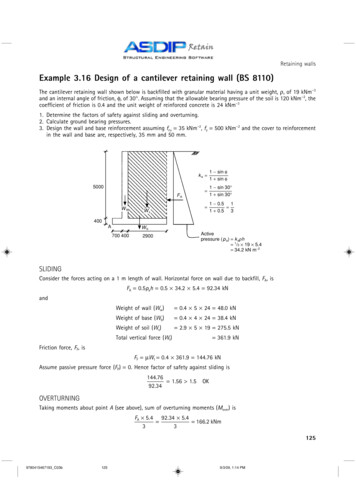
DurabilityMurata retaining wall system products are manufactured usinghigh-strength, low-slump 5000 psi machine-formed concrete. The Murata retaining wallsystem has a typical life expectancy of over 50 years.ValueThe initial cost of the Murata retaining wall system is competitive with other wall systemsand is significantly less expensive than most conventional concrete walls. The lastingaesthetics and structural durability of the concrete Murata retaining wall system makes it acost-effective solution whenlife-cycle costs are considered. This value is created in part by the installation rates of theretaining wall system. The Murata retaining wall system does not require special tools toinstall and the blocks can be moved by hand. The self-aligning tabs allow for highly accurateand quick installation.Soil CharacteristicsThe Murata retaining wall system is designed to resist a wedge of soil as illustrated inFigure 1. There are two types of soil in the Murata retaining wall system. The first typeof soil is the Murata fill. Murata fill is given as road base from Oregon, Washington, orIdaho’s Department of Transportation. Specifications of each Murata fill can be found in theMurata gravity wall specifications. The second type of soil is the retained soil. The retainedsoil may be native to the site or compacted fill due to regrading. Both types will have differentproperties.Figure 1Properties of this soil mass, including the internal angle of friction, wall friction angle, basefriction angle, cohesion, and unit weight, should be defined by a geotechnical engineer. Theseproperties should be used to calculate the active pressure, passive pressure, active seismicpressures, and soil bearing capacity through procedures outlined in this manual.It is essential to consult a qualified geotechnical engineer to obtain reasonable or optimalsoil properties. Reliance on a geotechnical report will lead to an accurate and optimizedwall design. In some cases, additional subsurface exploration and laboratory testing may beMurata Manual – Gravity SRWApril 2019Page 2 of 10Murata Retaining Wall System from Western Interlock. (US Patents Pending)
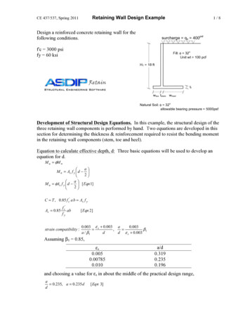
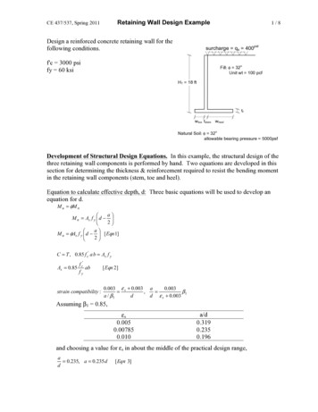
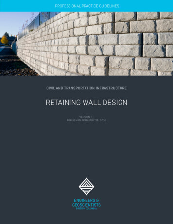
necessary to obtain reasonable soil properties for optimizing the wall design.Soil strength parameters should be based on drained conditions for granular soils as wellas fine grained soils for long-term stability. In this manual all soil parameters are based ondrained conditions, thus conforming to the effective stress analyses utilized in design.Design MethodologyThe sample calculations in this manual follow the methodology outlined in the NationalConcrete and Masonry Association’s (NCMA) Design Manual for Segmental Retaining WallsSection 6 (National Concrete Masonry Association, 2010).Forces on the WallLateral forces acting upon a segmental retaining wall arise from active soil pressure, activeseismic pressure, passive soil pressure, and induced surcharge pressure.Figure 2Active Soil Pressure: Active soil pressure causes a horizontal force applied to the retainingwall from the weight of the soil pushing laterally on the wall face (as shown in Figure 3). Theactive soil pressure is applied as an equivalent fluid pressure in the engineering design. It isa triangular pressure that increases from zero at the ground surface linearly with depth (asshown in Figure 2).Figure 3Murata Manual – Gravity SRWApril 2019Page 3 of 10Murata Retaining Wall System from Western Interlock. (US Patents Pending)
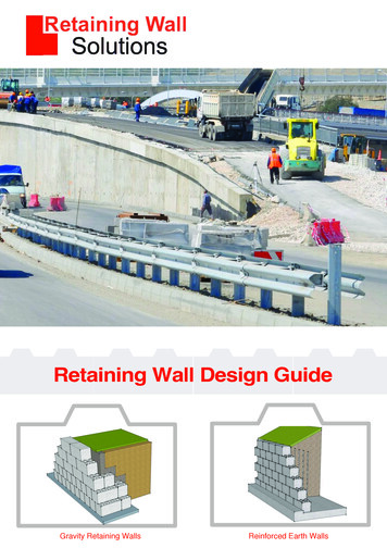
Active soil pressures are calculated based on the soil properties at the site. A geotechnicalengineer should be consulted to determine the on-site soil and Murata fill properties,and how to apply the soil forces for your project. Once given the soil properties, the activepressure coefficient will be calculated using Coulomb’s Theory of Active Lateral EarthPressure.It is important when calculating the active pressure on a retaining wall to compare the activepressure induced by the Murata fill to that of the retained soil. Murata fill may be heavier buthave a higher internal friction angle, resulting in a smaller active pressure when compared to thelighter retained soil with a typically lower internal friction angle. The higher active soil pressureshall be used.Passive Soil Pressure: Passive soil pressure is generated when the wall moves into the soil atthe toe (as shown in Figure 4), and results in a force resisting sliding at the base of the wall.The passive soil pressure distribution is triangular, increasing linearly from zero at the groundsurface to the base of the leveling pad. The NCMA Design Manual suggests a minimumembedment of 6” (National Concrete Masonry Association, 2010). A geotechnical engineershould be consulted for embedment recommendations on your project.Figure 4Passive soil pressure is calculated based on the soil properties at the site. It is recommendedthat passive soil pressure not be used in resisting active soil pressure, unless the embedmentis permanent and the material at the base of the wall is compacted per the geotechnicalengineer’s recommendations. Embedment is often not permanent and soil in front of the toeof the wall can erode or be removed. For these reasons, it is highly suggested a geotechnicalengineer should be consulted for on-site soil properties, and for guidance on how toapply the soil forces on your project. Once given the soil properties, the passive pressurecoefficient will be calculated using Coulomb’s Theory of Passive Lateral Earth Pressure.Active Seismic Pressures: The active seismic pressure is caused by lateral soil movement duringan earthquake. The active seismic pressure is often applied for design purposes as an invertedequivalent fluid pressure. The active seismic pressure is considered zero at the base of the walland increases linearly to the ground surface. Because this is, an overly conservative assumption,the resultant active seismic force is traditionally applied at 0.6H from the bottom of theretaining wall (as shown in Figure 2).Murata Manual – Gravity SRWApril 2019Page 4 of 10Murata Retaining Wall System from Western Interlock. (US Patents Pending)
Active seismic pressures are calculated based on the soil properties and the seismicity atthe site. The United States Geological Survey offers an online portal that produces seismicdesign criteria for any specific address (or latitude and longitude coordinates). A geotechnicalengineer should be consulted for on-site soil properties, site ground motion, and activeseismic pressure application. Once given the soil properties, the active pressure coefficientwill be calculated using the Mononobe-Okabe equation.It is important when calculating the active seismic pressure on a retaining wall to comparethe active seismic pressure induced by the Murata fill and the native soil. The larger activeseismic pressure shall be used.Uniform Surcharge Loads Above Retaining Wall: A uniform vertical pressure (psf) appliedto the top surface of the retained soil induces a horizontal pressure on the back side of theretaining wall.Surcharge pressures on the retaining wall are calculated based on the soil properties at thesite. A geotechnical engineer should be consulted foron-site soil properties and how to apply the surcharge forces on your project. Once giventhe soil properties, the active pressure coefficient will be calculated using Coulomb’s Theoryof Active Lateral Earth Pressure and multiplied by the vertical surcharge pressure to obtainthe induced lateral pressure on the retaining wall. This pressure is uniform with the resultanthalfway up the wall from the bottom (as shown in Figure 2).Typical light and heavy traffic surcharges are 125 psf and 250 psf, respectively.Special Design ConsiderationsStairs and RampsRetaining walls inherently create different levels. Adding a staircase or ramp allows accessbetween levels and offers a unique feature to your retaining wall. Murata blocks can beused to create multiple stair designs including curved, straight, and feature stairs. Additionalcompaction is required to ensure stairs do not settle.No Batter Gravity WallReturns parallel to stairs and some architectural styles dictate not using the 1” setback withthe typical Murata blocks. In these situations, stacking Murata base blocks and creatinga wall without batter is the solution. See the sample calculations for the analysis of a 2’-8”Murata gravity retaining wall system with no surcharge or batter and level backfill.Murata Manual – Gravity SRWApril 2019Page 5 of 10Murata Retaining Wall System from Western Interlock. (US Patents Pending)
No Fines ConcreteSome situations dictate the use of a stronger and heavier backfill. In this case, no finesconcrete is recommended. No fines concrete has a density of 100-120 pounds per cubic footand allows water to freely pass through in a manner similar to Murata fill. It would replacethe Murata fill both behind the wall and in the cells of the Murata blocks. Your localconcrete manufacturer should be contacted for available no fines concrete and its density foryour specific project.Tiered WallsIt is often advantageous to split one large retaining wall into two shorter walls offset by a tierdue to architectural requirements, aesthetics, and site layout. This allows vegetation to beplanted between the top of the lower wall and the bottom of the upper wall.Murata Manual – Gravity SRWApril 2019Page 6 of 10Murata Retaining Wall System from Western Interlock. (US Patents Pending)
The lower wall shall have a greater height than the upper wall. The engineer of record shallconsider the additional load on the lower wall imposed by the upper wall. The general rule ofthumb is that the toe of the upper wall shall be set back from the toe of the lower wall by aminimum horizontal distance of twice the height of the lower wall in order for there to be noinfluence of the upper wall on the lower wall’s stability. Consult the NCMA Design Manualfor Segmental Retaining Walls, Section 5.9.2, for more information on tiered walls (NationalConcrete Masonry Association, 2010).Wall FailureWhen designing any retaining wall, there are many different failure modes the designprofessional has to consider. These include block sliding, foundation sliding, bearing failure,overturning, internal sliding, internal overturning, and global stability.Block SlidingThe blocks can slide on the leveling pad due to the lateralforces induced by the soil on the wall. The lateral forces areresisted by the friction developed from the weight of the walland the vertical component of earth pressure. The designprofessional should check that the resistive frictional forcesbetween the base blocks and the leveling pad are adequate toresist the driving soil forces.Foundation SlidingThe leveling pad base can slide horizontally on thefoundation soil. The lateral forces are resisted by the frictiondeveloped from the weight of the wall and the verticalcomponent of earth pressure. The design professionalshould check that the resistive frictional forces between theleveling pad and the foundation soil are adequate to resistthe driving soil forces.Internal Block SlidingThe blocks can slide in relation to one another due tothe lateral forces induced by the soil on the wall. Thelateral forces are resisted by the friction developed fromthe weight of the wall and the vertical component ofearth pressure. This can happen on any level. The designprofessional should check that each level of block cannotslide laterally off the front of the wall. Friction and a positiveconnection can be used to resist lateral sliding. Murata wall systems provide a positive connection resistance withthe addition of a concrete “nub” on the bottom rear of theblock.Murata Manual – Gravity SRWApril 2019Page 7 of 10Murata Retaining Wall System from Western Interlock. (US Patents Pending)
Bearing Stresses on Foundation SoilsThe bearing pressure imparted on the soil must be lessthan the foundation soil’s bearing capacity. A Meyerhofdistribution analysis should be utilized. This methodcalculates an equivalent bearing pressure distributionneeded to balance the vertical loads (the weight of thewall itself in addition to the vertical component of earthpressure), as well as the overturning moments createdby lateral and vertical earth pressures, and verticalload eccentricity. A geotechnical engineer shouldbe consulted regarding the bearing capacity of thefoundation soil and the necessary size of the levelingpad required to maintain overturning stability.Global and Internal Wall OverturningDue to the application of lateral load at height, the resistance of the wall to rotate about apoint on the front of the wall must be checked. The overturning point may be at the bottomfront of the wall, but internal overturning must also be evaluated.Internal OverturningMurata Manual – Gravity SRWApril 2019Global Stability OverturningPage 8 of 10Murata Retaining Wall System from Western Interlock. (US Patents Pending)
Global StabilityThe last mode of failure for a gravity retaining wall is the global stability of the surroundingsoil. This results in a failure surface in the soil around the retaining wall. A geotechnicalengineer should be consulted for requirements to avoid global soil instabilities.TestingThe Murata gravity retaining wall system conforms to all American Society of Testing andMaterials (ASTM) standards, culminating in an International Code Council Evaluation Service(ICC-ES) report, also known as an ESR.Murata blocks have gone through the following ASTM standards and testing:ASTM C1372 Standard Specification for Segmental Retaining Wall UnitsASTM C1262 Evaluating the Freeze Thaw Durability of Manufactured CMUs and RelatedConcrete UnitsASTM D6638 Grid Connection Strength (SRW-U1)ASTM D6916 SRW Block Shear Strength (SRW-U2)The results from the above-listed standards are summarized below:Block Height Hu 8"Block Depth Du 12 5/16"Block Width Wu 15 3/4"Offset 1"Average Block Density w/ Murata Fill γu 121.5 lbs/ft³Block to Block Peak Shear Strength 0.74N 449.46 lbs/ftBlock to Block Service Shear Strength 1.01N 166.77 lbs/ftMurata Manual – Gravity SRWApril 2019Page 9 of 10Murata Retaining Wall System from Western Interlock. (US Patents Pending)
Block PropertiesThe Murata gravity retaining wall system hastwo individual block designs. The differencebetween the two designs is the presence orabsence of the alignment shear tab on the backside of the block.The shear tab allows for easy alignment in thefield during construction. However, wherethe base block is sitting on a leveling pad ofcompacted Murata fill, the shear tab is notneeded.The shear tab contributes to the strength of theMurata gravity retaining wall system to resisthorizontal lateral movement between courses.Using formulas from the American ConcreteInstitute’s (ACI) 318-11 code, the apparent shearcapacity that the shear tab contributes to thestrength of the Murata gravity retaining wallsystem to resist horizontal lateral movementbetween courses can be calculated (AmericanConcrete Institute, 2012).The concrete used to manufacture the Murata blocks has a density of 131 pounds per cubicfoot (pcf).Compaction of the block core Murata fill isoptional. When the central portion of the blockis filled with loosely placed Murata fill, the resulting average density of the core fill and block is121.5 pcf based on laboratory testing performed using Oregon Department of Transportation’s(ODOT) ¾-inch minus road base. See the Murata gravity wall specifications for ODOT roadbase. This is the density that is used in the following example analysis. Note: The averagedensity will vary based on the select granular material type and source and may need to bechecked by a geotechnical engineer.Murata Manual – Gravity SRWApril 2019Page 10 of 10Murata Retaining Wall System from Western Interlock. (US Patents Pending)
Active Seismic Pressures: The active seismic pressure is caused by lateral soil movement during an earthquake. The active seismic pressure is often applied for design purposes as an inverted equivalent fluid pressure. The active seismic pressure is considered zero at the base