Transcription
Chapter 77.17.27.37.4ContentsGeneral Substructure Considerations . . . . . . . . . . . . . . . . . . . . . . . . . . . . . . . . . . . . . . . . . . . . 7-17.1.1Foundation Design Process . . . . . . . . . . . . . . . . . . . . . . . . . . . . . . . . . . . . . . . . . . . . . 7-17.1.2Foundation Design Limit States . . . . . . . . . . . . . . . . . . . . . . . . . . . . . . . . . . . . . . . . . . 7-37.1.3Seismic Design . . . . . . . . . . . . . . . . . . . . . . . . . . . . . . . . . . . . . . . . . . . . . . . . . . . . . . 7-47.1.4Substructure and Foundation Loads . . . . . . . . . . . . . . . . . . . . . . . . . . . . . . . . . . . . . . 7-47.1.5Concrete Class for Substructure . . . . . . . . . . . . . . . . . . . . . . . . . . . . . . . . . . . . . . . . . 7-77.1.6Foundation Seals . . . . . . . . . . . . . . . . . . . . . . . . . . . . . . . . . . . . . . . . . . . . . . . . . . . . . 7-77.1.7Scour Requirements . . . . . . . . . . . . . . . . . . . . . . . . . . . . . . . . . . . . . . . . . . . . . . . . . 7-10Foundation Modeling for Seismic Loads . . . . . . . . . . . . . . . . . . . . . . . . . . . . . . . . . . . . . . . . . 7-127.2.1General . . . . . . . . . . . . . . . . . . . . . . . . . . . . . . . . . . . . . . . . . . . . . . . . . . . . . . . . . . . 7-127.2.2Substructure Elastic Dynamic Analysis Procedure . . . . . . . . . . . . . . . . . . . . . . . . . . . 7-127.2.3Bridge Model Section Properties . . . . . . . . . . . . . . . . . . . . . . . . . . . . . . . . . . . . . . . . 7-137.2.4Bridge Model Verification . . . . . . . . . . . . . . . . . . . . . . . . . . . . . . . . . . . . . . . . . . . . . 7-157.2.5Deep Foundation Modeling Methods . . . . . . . . . . . . . . . . . . . . . . . . . . . . . . . . . . . . 7-157.2.6Lateral Analysis of Piles and Shafts . . . . . . . . . . . . . . . . . . . . . . . . . . . . . . . . . . . . . . 7-207.2.7Spread Footing Modeling . . . . . . . . . . . . . . . . . . . . . . . . . . . . . . . . . . . . . . . . . . . . . 7-25Column Design . . . . . . . . . . . . . . . . . . . . . . . . . . . . . . . . . . . . . . . . . . . . . . . . . . . . . . . . . . . . 7-287.3.1General Design Considerations . . . . . . . . . . . . . . . . . . . . . . . . . . . . . . . . . . . . . . . . . 7-287.3.2Slenderness Effects . . . . . . . . . . . . . . . . . . . . . . . . . . . . . . . . . . . . . . . . . . . . . . . . . . 7-297.3.3Shear Design . . . . . . . . . . . . . . . . . . . . . . . . . . . . . . . . . . . . . . . . . . . . . . . . . . . . . . . 7-317.3.4Column Silos . . . . . . . . . . . . . . . . . . . . . . . . . . . . . . . . . . . . . . . . . . . . . . . . . . . . . . . 7-317.3.5Column Reinforcement . . . . . . . . . . . . . . . . . . . . . . . . . . . . . . . . . . . . . . . . . . . . . . . 7-337.3.6Column and Wall Pier Hinges . . . . . . . . . . . . . . . . . . . . . . . . . . . . . . . . . . . . . . . . . . 7-457.3.7Reduced Column Section . . . . . . . . . . . . . . . . . . . . . . . . . . . . . . . . . . . . . . . . . . . . . 7-47Crossbeams . . . . . . . . . . . . . . . . . . . . . . . . . . . . . . . . . . . . . . . . . . . . . . . . . . . . . . . . . . . . . . . 7-517.4.17.5Substructure DesignGeneral Design . . . . . . . . . . . . . . . . . . . . . . . . . . . . . . . . . . . . . . . . . . . . . . . . . . . . . 7-51Abutment Design and Details . . . . . . . . . . . . . . . . . . . . . . . . . . . . . . . . . . . . . . . . . . . . . . . . . 7-547.5.1General . . . . . . . . . . . . . . . . . . . . . . . . . . . . . . . . . . . . . . . . . . . . . . . . . . . . . . . . . . . 7-547.5.2Abutments Supported By Mechanically-Stabilized Earth Walls . . . . . . . . . . . . . . . . . 7-587.5.3Embankment at Abutments . . . . . . . . . . . . . . . . . . . . . . . . . . . . . . . . . . . . . . . . . . . . 7-637.5.4Abutment Loading . . . . . . . . . . . . . . . . . . . . . . . . . . . . . . . . . . . . . . . . . . . . . . . . . . . 7-637.5.5Temporary Construction Load Cases . . . . . . . . . . . . . . . . . . . . . . . . . . . . . . . . . . . . . 7-647.5.6Abutment Bearings and Girder Stops . . . . . . . . . . . . . . . . . . . . . . . . . . . . . . . . . . . . 7-65WSDOT Bridge Design Manual M 23-50.20September 2020Page 7-i
Chapter 77.67.77.87.9Substructure Design7.5.7Abutment Expansion Joints . . . . . . . . . . . . . . . . . . . . . . . . . . . . . . . . . . . . . . . . . . . . 7-677.5.8Open Joint Details . . . . . . . . . . . . . . . . . . . . . . . . . . . . . . . . . . . . . . . . . . . . . . . . . . . 7-677.5.9Construction Joints . . . . . . . . . . . . . . . . . . . . . . . . . . . . . . . . . . . . . . . . . . . . . . . . . . 7-697.5.10Abutment Wall Design . . . . . . . . . . . . . . . . . . . . . . . . . . . . . . . . . . . . . . . . . . . . . . . 7-697.5.11Drainage and Backfilling . . . . . . . . . . . . . . . . . . . . . . . . . . . . . . . . . . . . . . . . . . . . . . 7-71Abutment Wing Walls and Curtain Walls . . . . . . . . . . . . . . . . . . . . . . . . . . . . . . . . . . . . . . . . 7-737.6.1Traffic Barrier Loads . . . . . . . . . . . . . . . . . . . . . . . . . . . . . . . . . . . . . . . . . . . . . . . . . 7-737.6.2Wing Wall Design . . . . . . . . . . . . . . . . . . . . . . . . . . . . . . . . . . . . . . . . . . . . . . . . . . . 7-737.6.3Wing Wall Detailing . . . . . . . . . . . . . . . . . . . . . . . . . . . . . . . . . . . . . . . . . . . . . . . . . 7-73Footing Design . . . . . . . . . . . . . . . . . . . . . . . . . . . . . . . . . . . . . . . . . . . . . . . . . . . . . . . . . . . . . 7-747.7.1General Footing Criteria . . . . . . . . . . . . . . . . . . . . . . . . . . . . . . . . . . . . . . . . . . . . . . 7-747.7.2Loads and Load Factors . . . . . . . . . . . . . . . . . . . . . . . . . . . . . . . . . . . . . . . . . . . . . . 7-757.7.3Geotechnical Report Summary . . . . . . . . . . . . . . . . . . . . . . . . . . . . . . . . . . . . . . . . . 7-767.7.4Spread Footing Design . . . . . . . . . . . . . . . . . . . . . . . . . . . . . . . . . . . . . . . . . . . . . . . 7-777.7.5Pile-Supported Footing Design . . . . . . . . . . . . . . . . . . . . . . . . . . . . . . . . . . . . . . . . . 7-82Shafts . . . . . . . . . . . . . . . . . . . . . . . . . . . . . . . . . . . . . . . . . . . . . . . . . . . . . . . . . . . . . . . . . . . . 7-857.8.1Axial Resistance . . . . . . . . . . . . . . . . . . . . . . . . . . . . . . . . . . . . . . . . . . . . . . . . . . . . . 7-857.8.2Structural Design and Detailing . . . . . . . . . . . . . . . . . . . . . . . . . . . . . . . . . . . . . . . . . 7-90Piles and Piling . . . . . . . . . . . . . . . . . . . . . . . . . . . . . . . . . . . . . . . . . . . . . . . . . . . . . . . . . . . . . 7-987.9.1Pile Types . . . . . . . . . . . . . . . . . . . . . . . . . . . . . . . . . . . . . . . . . . . . . . . . . . . . . . . . . 7-987.9.2Single Pile Axial Resistance . . . . . . . . . . . . . . . . . . . . . . . . . . . . . . . . . . . . . . . . . . . 7-1007.9.3Block Failure . . . . . . . . . . . . . . . . . . . . . . . . . . . . . . . . . . . . . . . . . . . . . . . . . . . . . . 7-1007.9.4Pile Uplift . . . . . . . . . . . . . . . . . . . . . . . . . . . . . . . . . . . . . . . . . . . . . . . . . . . . . . . . 7-1007.9.5Pile Spacing . . . . . . . . . . . . . . . . . . . . . . . . . . . . . . . . . . . . . . . . . . . . . . . . . . . . . . . 7-1007.9.6Structural Design and Detailing of CIP Concrete Piles . . . . . . . . . . . . . . . . . . . . . . . 7-1017.9.7Pile Splices . . . . . . . . . . . . . . . . . . . . . . . . . . . . . . . . . . . . . . . . . . . . . . . . . . . . . . . . 7-1027.9.8Pile Lateral Design . . . . . . . . . . . . . . . . . . . . . . . . . . . . . . . . . . . . . . . . . . . . . . . . . . 7-1027.9.9Battered Piles . . . . . . . . . . . . . . . . . . . . . . . . . . . . . . . . . . . . . . . . . . . . . . . . . . . . . 7-1027.9.10Pile Tip Elevations and Quantities . . . . . . . . . . . . . . . . . . . . . . . . . . . . . . . . . . . . . . 7-1037.9.11Plan Pile Resistance . . . . . . . . . . . . . . . . . . . . . . . . . . . . . . . . . . . . . . . . . . . . . . . . . 7-103Page 7-iiWSDOT Bridge Design Manual M 23-50.20September 2020
Substructure Design7.10Chapter 7Concrete-Filled Steel Tubes . . . . . . . . . . . . . . . . . . . . . . . . . . . . . . . . . . . . . . . . . . . . . . . . . 7-1047.10.1Scope . . . . . . . . . . . . . . . . . . . . . . . . . . . . . . . . . . . . . . . . . . . . . . . . . . . . . . . . . . . 7-1047.10.2Design Requirements . . . . . . . . . . . . . . . . . . . . . . . . . . . . . . . . . . . . . . . . . . . . . . . 7-1057.10.3CFST-to-Cap Annular Ring Connections . . . . . . . . . . . . . . . . . . . . . . . . . . . . . . . . . 7-1107.10.4CFST-to-Cap Reinforced Concrete Connections . . . . . . . . . . . . . . . . . . . . . . . . . . . 7-1157.10.5RCFST-to-Column and CFST-to Column Connections . . . . . . . . . . . . . . . . . . . . . . . 7-1187.10.6Partially-filled CFST . . . . . . . . . . . . . . . . . . . . . . . . . . . . . . . . . . . . . . . . . . . . . . . . . 7-1207.10.7Construction Requirements . . . . . . . . . . . . . . . . . . . . . . . . . . . . . . . . . . . . . . . . . . . 7-1217.10.8Notation . . . . . . . . . . . . . . . . . . . . . . . . . . . . . . . . . . . . . . . . . . . . . . . . . . . . . . . . . 7-1227.11Bridge Standard Drawings . . . . . . . . . . . . . . . . . . . . . . . . . . . . . . . . . . . . . . . . . . . . . . . . . . . 7-1247.12Appendices . . . . . . . . . . . . . . . . . . . . . . . . . . . . . . . . . . . . . . . . . . . . . . . . . . . . . . . . . . . . . . 7-1257.99Appendix 7.3-A2Noncontact Lap Splice Length Column to Shaft Connections . . . . . . . . 7-126Appendix 7-B1Linear Spring Calculation Method II (Technique I) . . . . . . . . . . . . . . . . . . 7-128Appendix 7-B2Pile Footing Matrix Example Method II (Technique I) . . . . . . . . . . . . . . . 7-134Appendix 7-B3Non-Linear Springs Method III . . . . . . . . . . . . . . . . . . . . . . . . . . . . . . . . . . 7-137References . . . . . . . . . . . . . . . . . . . . . . . . . . . . . . . . . . . . . . . . . . . . . . . . . . . . . . . . . . . . . . . 7-139WSDOT Bridge Design Manual M 23-50.20September 2020Page 7-iii
Chapter 7Substructure DesignPage 7-ivWSDOT Bridge Design Manual M 23-50.20September 2020
Chapter 77.1Substructure DesignGeneral Substructure ConsiderationsNote that in the following guidelines where reference is made to AASHTO LRFD the itemcan be found in the current AASHTO LRFD Bridge Design Specifications (LRFD). And forany reference to AASHTO Seismic, the item can be found in the current AASHTO GuideSpecifications for LRFD Seismic Bridge Design (SEISMIC).7.1.1Foundation Design ProcessA flowchart is provided in which illustrates the overall design process utilized bythe WSDOT Bridge and Structures Office to accomplish an LRFD foundation design.Note this process is also outlined in the Geotechnical Design Manual Section 8.2. TheBridge and Structures Office (BSO), the WSDOT Geotechnical Branch (GB) and theWSDOT Hydraulics Branch (HB) have been abbreviated. The steps in the flowchartare defined as follows:A. Scoping Level DesignThis phase of the design process involves the region requesting initial bridge optionsand costs for a future project. Depending on the complexity of the project, this phasecould include a Type, Size and Location (TS&L) Report.This design step may result in informal communication between the BSO and theGB and/or HB with the request for preliminary information and recommendations.The level of communication will depend on the available information providedby the region and the complexity of the project. The type of information that may bereceived from the GB and HB are as follows: Anticipated soil site conditions. Maximum embankment slopes. Possible foundation types and geotechnical hazards such as liquefaction. Scour potential for piers if a water crossing. Potential for future migration of a stream or river crossing.In general, these recommendations rely on existing site data. Site borings may notbe available and test holes are drilled later. The GB provides enough informationto select potential foundation types for an initial scoping level or TS&L level planand estimate.WSDOT Bridge Design Manual M 23-50.20September 2020Page 7-1
Chapter 7Substructure DesignB.Develop Site Data and Preliminary Bridge PlanIn the second phase, the BSO obtains site data from the region, see Section 2.2,and develops the preliminary bridge plan. The preliminary pier locations determinesoil boring locations at this time. The GB and/or the HB may require the followinginformation to continue their preliminary design. Structure type and magnitude of settlement the structure can tolerate (both totaland differential). At abutments – Approximate maximum top of foundation elevation. At interior piers – The initial size, shape and number of columns and how theyare configured with the foundation (e.g., whether a single foundation elementsupports each column, or one foundation element supports multiple columns) At water crossings – Pier scour depth, if known, and any potential for migration ofthe water crossing in the future. Typically, the GB and the BSO should coordinatepursuing this information with the HB. Any known structural constraints that affect the foundation type, size, or location. Any known constraints that affect the soil resistance (utilities, constructionstaging, excavation, shoring, and falsework).C.Preliminary Foundation DesignThe third phase is a request by the BSO for a preliminary foundation memorandum.The GB memo will provide preliminary soil data required for structural analysisand modeling. This includes any subsurface conditions and the preliminarysubsurface profile.The concurrent geotechnical work at this stage includes: Completion of detailed boring logs and laboratory test data. Development of foundation type, soil capacity, and foundation depth. Development of static/seismic soil properties and ground acceleration. Recommendations for constructability issues.The BSO may also request the HB to provide preliminary scour designrecommendations if the structure is located over a water crossing.D. Structural Analysis and ModelingIn the fourth phase, the BSO performs a structural analysis of the superstructureand substructure using a bridge model and preliminary soil parameters. Throughthis modeling, the designer determines loads and sizes for the foundation based onthe controlling LRFD limit states. Structural and geotechnical design continues toinvestigate constructability and construction staging issues during this phase.Page 7-2WSDOT Bridge Design Manual M 23-50.20September 2020
Substructure DesignChapter 7In order to produce a final geotechnical report, the BSO provides the followingstructural feedback to the State Geotechnical Engineer: Foundation loads for service, strength, and extreme limit states. Foundation size/diameter and depth required to meet structural design. Foundation details that could affect the geotechnical design of the foundations. Foundation layout plan. Assumed scour depths for each limit state (if applicable)For water crossings, the BSO also provides the information listed above to the StateHydraulic Engineer to verify initial scour and hydraulics recommendations are stillsuitable for the site.(See Chapter 2 for examples of pile design data sheets that shall be filled out andsubmitted to the State Geotechnical Engineer at the early stage of design.)E.Final Foundation DesignThe last phase completes the geotechnical report and allows the final structuraldesign to begin. The preliminary geotechnical assumptions are checked andrecommendations are modified, if necessary. The final report is complete to aPS&E format since the project contract will contain referenced information in thegeotechnical report, such as: All geotechnical data obtained at the site (boring logs, subsurface profiles,and laboratory test data). All final foundation recommendations. Final constructability and staging recommendations.The designer reviews the final report for new information and confirms thepreliminary assumptions. With the foundation design complete, the final bridgestructural design and detailing process continues to prepare the bridge plans.Following final structural design, the structural designer shall follow up withthe geotechnical designer to ensure that the design is within the limits of thegeotechnical report.7.1.2Foundation Design Limit StatesThe controlling limit states for WSDOT projects for substructure design are described asfollows:Strength IStrength IIIStrength VExtreme-Event IService IWSDOT Bridge Design Manual M 23-50.20September 2020Relating to the normal vehicular useRelating to the bridge exposed to windRelating to the normal vehicular use and windRelating to earthquakeRelating to normal operational use and windPage 7-3
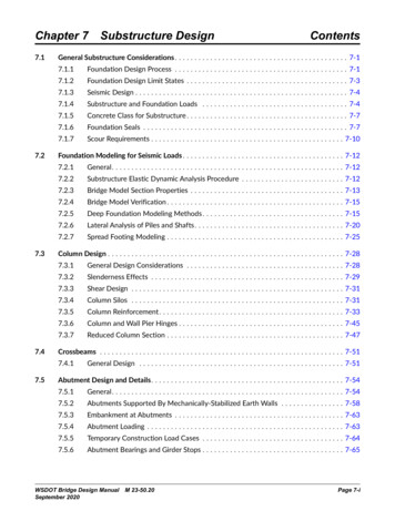
Chapter 77.1.3Substructure DesignSeismic DesignThe seismic design of all substructures shall be in accordance with the AASHTO Seismic except as noted otherwise.7.1.4Substructure and Foundation LoadsFigure 7.1.4-1 below provides a common basis of understanding for load location andorientations for substructure design. This figure also shows elevations required forabutment and substructure design. Note that for shaft and some pile foundation designs,the shaft or pile may form the column as well as the foundation element.Spread footings usually have a design orientation normal to the footing. Since bridgeloads are longitudinal and transverse, skewed superstructure loads are converted (usingvector components) to normal and parallel footing loads. Deep foundation analysis usuallyhas a normal/parallel orientation to the pier in order to simplify group effects.Substructure elements are to carry all of the loads specified in AASHTO Seismic andAASHTO LRFD. Selecting the controlling load conditions requires good judgment tominimize design time. All anticipated dead load (DC) conditions shall be accounted forduring a substructure design. Sidesway effect shall be included where it tends to increasestresses. For live loads (LL), the dynamic allowance (IM) shall be applied in accordancewith AASHTO LRFD Section 3.6.2 and is not included in the design of buried elementsof the substructure. Portions of the abutments in contact with the soil are consideredburied elements.Page 7-4WSDOT Bridge Design Manual M 23-50.20September 2020
Substructure DesignFigure 7.1.1-1Chapter 7Overall Design Process for LRFD Foundation Design WSDOT Bridge Design Manual M 23-50.20September 2020Page 7-5
Chapter 7Substructure DesignBridge design shall consider construction loads to ensure structural stability andprevent members from overstress. For example, temporary construction loads causedby placing all of the precast girders on one side of a crossbeam can overload a singlecolumn pier. Construction loads shall also include live loads from potential constructionequipment. The plans shall show a construction sequence and/or notes to avoidunacceptable loadings.On curved bridges, the substructure design shall consider the eccentricity resulting fromthe difference in girder lengths and the effects of torsion. When superstructure designuses a curved girder theory, such as the V-Load Method, the reactions from such analysismust be included in the loads applied to the substructure.Figure 7.1.4-1Substructure Directional Forces Page 7-6WSDOT Bridge Design Manual M 23-50.20September 2020
Substructure Design7.1.5Chapter 7Concrete Class for SubstructureThe concrete class for all substructure elements shall be Class 4000. This includesfootings, pedestals, massive piers, columns, crossbeams, traffic barriers, andretaining walls, wing walls, and curtain walls connected to the bridge substructure orsuperstructure. Foundation seals shall be Class 4000W. Shafts and cast-in-place pilesshall be Class 5000P. Concrete Class 4000P may be used for elements other thanbridge foundations.7.1.6Foundation SealsA concrete seal within the confines of a cofferdam permits construction of a pier footingand column in the dry. This type of underwater construction is practical to a water depthof approximately 50 feet.Seal concrete is placed underwater with the use of a tremie. A tremie is a long pipethat extends to the bottom of the excavation and permits a head to be maintained onthe concrete during placement. After the concrete has been placed and has obtainedsufficient strength, the water within the cofferdam is removed. In Figure 7.1.6-1, some ofthe factors that must be considered in designing a seal are illustrated.Figure 7.1.6-1Foundation Seal WSDOT Bridge Design Manual M 23-50.20September 2020Page 7-7
Chapter 7Substructure DesignA. General Seal CriteriaThe normal high water elevation is defined as the highest water surface elevationthat may normally be expected to occur during a given time period. This elevation,on the hydraulics data sheet, is obtained from discussions with local residentsor by observance of high water marks at the site. The normal high water is not relatedto any flood condition.1.Seal Vent ElevationThe Hydraulics Branch recommends a seal vent elevation in accordance with thefollowing criteria.i.Construction Time Period Not KnownIf the time period of the footing construction is not known, the ventelevation reflects the normal high water elevation that might occurat any time during the year.ii. Construction Time Period KnownIf the time period of the footing construction can be anticipated, thevent elevation reflects the normal high water elevation that might occurduring this time period. (If the anticipated time period of constructionis later changed, the Hydraulics Branch shall be notified and appropriatechanges made in the design.)2.Scour DepthThe Hydraulics Branch determines the depth of the anticipated scour. Thebottom of footing, or bottom of seal if used, shall be no higher than 2 feetbelow the 500 year scour depth elevation. After preliminary footing andseal thicknesses have been determined, the bridge designer shall review theanticipated scour elevation with the State Hydraulic Engineer to ensure thatexcessive depths are not used.3.Foundation Elevation Recommended in Geotechnical ReportBased on the results obtained from test borings at the site, the StateGeotechnical Engineer determines a foundation elevation, bearing capacity andsettlement criteria. If other factors control, such as scour or footing cover, thefinal footing elevation shall be adjusted as required.4.Unusual ConditionsUnusual site conditions such as rock formations or deep foundations requirespecial considerations in order to obtain the most optimum design. Theproposed foundation design/construction shall be discussed with both the StateGeotechnical Engineer and the State Hydraulics Engineer Branch prior to finalplan preparation.Page 7-8WSDOT Bridge Design Manual M 23-50.20September 2020
Substructure DesignB.Chapter 7Spread Footing SealsThe Geotechnical Branch will generally recommend whether a foundation seal may ormay not be required for construction. Bearing loads are the column moments appliedat the base of the footing and vertical load applied at the bottom of the seal. The sealis sized for the soil bearing capacity. Overturning stability need only be checked atthe base of the pier footing.1.When a Seal is Required During ConstructionIf the footing can be raised without violating cover requirements, the bottom ofthe seal elevation shall be the lower of 2 feet below the 500 year scour elevationor the foundation elevation as recommended by the State Geotechnical Engineer.The bottom of the seal may be lower than the scour elevation or foundationelevation due to cover requirements. Spread footing final design shall include thedead load weight of the seal.2.When a Seal May Not Be Required for ConstructionBoth methods of construction are detailed in the plans when it is not clear ifa seal is required for construction. The plans must detail a footing with a sealand an alternate without a seal. The plan quantities are based on the footingdesigned with a seal. If the alternate footing elevation is different from thefooting with seal, it is also necessary to note on the plans the required changes inrebar such as length of column bars, increased number of ties, etc. Note that thisrequires the use of either General Special Provision (GSP) 6-02.3(6)B.OPT1.GB6or 6-02.3(6)B.OPT2.GB6.C.Pile Footing SealsThe top of footing, or pedestal, is set by the footing cover requirements. The bottomof seal elevation is based on the stream scour elevation determined by the HydraulicsBranch. A preliminary analysis is made using the estimated footing and seal weight,and the column moments and vertical load at the base of the footing to determinethe number of piles and spacing. The seal size shall be 1′-0″ larger than the footing allaround. If the seal is omitted during construction, the bottom of footing shall be setat the scour elevation and
Chapter 7 Substructure Design Page 7-4 WSDOT Bridge Design Manual M 23-50.20 September 2020. 7.1.3 Seismic Design. The seismic design of all substructures shall be in accordance with the AASHTO Seismic - except as