Transcription
IET Standards Technical BriefingSupported by:Electrical Energy Storage:an introduction
CONTENTS1Introduction12Reasons and benefits23Selecting systems54Electrical arrangements175References and related documents216Terminology22AcknowledgementsLead technical authorEUR ING Graham Kenyon BEng(Hons) CEng MIET (G Kenyon Technology Ltd)We would like to thank members of the IET Standards Technical Committee 3.3 Electrical EnergyStorage Systems for their contribution to this publication.Publication InformationPublished by The Institution of Engineering and Technology, London, United KingdomThe Institution of Engineering and Technology is registered as a Charity in England & Wales (no.211014) and Scotland (no. SC038698). The Institution of Engineering and Technology 2016This publication is copyright under the Berne Convention and the Universal CopyrightConvention. All rights reserved. Apart from any fair dealing for the purposes of research or privatestudy, or criticism or review, as permitted under the Copyright, Designs and Patents Act 1988, thispublication may be reproduced, stored or transmitted, in any form or by any means, only withthe prior permission in writing of the publishers, or in the case of reprographic reproduction inaccordance with the terms of licences issued by the Copyright Licensing Agency. Enquiriesconcerning reproduction outside those terms should be sent to the publisher at this address:The Institution of Engineering and TechnologyMichael Faraday HouseSix Hills Way, StevenageHerts, SG1 2AY, United Kingdomwww.theiet.orgWhile the publisher, author and contributors believe that the information and guidance given inthis work is correct, all parties must rely upon their own skill and judgement when making use of it.Neither the publisher, nor the author, nor any contributors assume any liability to anyone for any loss ordamage caused by any error or omission in the work, whether such error or omission is the result ofnegligence or any other cause. Any and all such liability is disclaimed.4HE MORAL RIGHTS OF THE AUTHOR TO BE IDENTIÇED AS AUTHOR OF THIS WORK HAVE BEEN ASSERTED BY HIM IN accordance with the Copyright, Designs and Patents Act 1988.This publication does not purport to include all the necessary provisions of a contract. Users areresponsible for its correct application. Compliance with the contents of this document cannot conferimmunity from legal obligations.It is the constant aim of the IET to improve the quality of our products and services. We should beGRATEFUL IF ANYONE ÇNDING AN INACCURACY OR AMBIGUITY WHILE USING THIS DOCUMENT WOULD INFORM THE IET standards development team at IETStandardsStaff@theiet.org or The IET, Six Hills Way, StevenageSG1 2AY, UK. The Institution of Engineering and Technology
1SECTION 1IntroductionElectrical energy storage systems (EESS) for electrical installations are becoming moreprevalent.EESS provide storage of electrical energy so that it can be used later. The approach isnot new: EESS in the form of battery-backed uninterruptible power supplies (UPS) havebeen used for many years. EESS are starting to be used for other purposes. There areseveral reasons behind the increasing use of EESS:(a) they make renewable energy more effective by ensuring that the energy thatis generated by renewable sources is available when that energy source is notavailable. EESS can be used either to ensure that all energy generated can beused locally in addition to the grid supply or to provide total independence fromthe public supply.(b) they make energy available during loss of the grid supply, enabling, for example:(i) 'controlled shutdown' of data centres and other computer and controlsystems to prevent corruption of stored data that would otherwise occur ifthe power was to be removed abruptly.(ii) electrical and electronic products and infrastructure to be used duringpower outages.(c) they allow for grid support services, including fast frequency response, demandand supply management, network constraints, and power quality management.These services could be aggregated over a number of sites and are notnecessarily located on generation sites.(d) the falling cost of EESS, notably lithium ion batteries.This Technical Briefing supports the forthcoming IET Code of Practice for ElectricalEnergy Storage Systems.The scope of this Technical Briefing is limited to EESS technology that is based onelectrochemical batteries and their associated charging control and protection systems.These are the predominant current and emerging technologies that are intended for use:(a) with common low voltage (LV) supplies in use in the UK; and(b) within electrical installations that are not part of the public electricity supplynetwork. The Institution of Engineering and Technology1
SECTION 2Reasons and benefits2.1 OverviewTable 2.1 outlines the principal benefits, with respect to both embedded generation anddemand and availability of the public supply.T Table 2.1Type ofinstallationDwellingsPrincipal benefits of energy storage solutions0RINCIPAL BENEÇTS OF ELECTRICAL ENERGY STORAGE2ELATING TO EMBEDDED GENERATION GENERATION FROM renewables2ELATING TO DEMAND AND availability of the publicsupplyAvailability of locally generatedenergy, when the energy source(daylight, wind) is not available.In rural locations, independenceof the public supply may bepossible.Low power loads could besupplied during extended periodsof supply outage. This mayinclude power forcommunications and datadevices/device charging, media,LED lighting and heating control/ignition for non-electric heatingequipment.Embedded grid-demand support.In rural or remote locations,independence of the publicsupply may be possible with localrenewable generation.Reduce energy costs by chargingOFF PEAK WHERE THE LOAD PROÇLE is high at peak demand periods(e.g. for homeworkers), subject toan appropriate tariff.Commercial/OFÇCE premisesAvailability of locally generatedenergy, when the energy source(daylight, wind, CHP) is notproviding generation.Embedded grid-demand support.Low power loads could besupplied during extended periodsof supply outage. This mayinclude power forcommunications and datadevices/device charging, media,LED lighting and heating control/ignition for non-electric heatingequipment.Reduce energy costs by chargingOFF PEAK WHERE THE LOAD PROÇLE is high at peak demand periods,subject to an appropriate tariff.2 The Institution of Engineering and Technology
Type ofinstallationIndustrialpremises keyinfrastructure0RINCIPAL BENEÇTS OF ELECTRICAL ENERGY STORAGE2ELATING TO EMBEDDED GENERATION GENERATION FROM renewables2ELATING TO DEMAND AND availability of the publicsupplyOptimise the use of any locallyReduce energy costs by charginggenerated energy from renewable OFF PEAK WHERE THE LOAD PROÇLE sources.is high at peak demand periods,subject to an appropriate tariff.Provide power for safety ormission critical functionality whenthe public supply is lost, until local(prime mover) generationcommences.Transport etc.infrastructureLocal generation (e.g. by solar PV charging) provides independenceFROM A ÇXED SUPPLY FOR LOW POWER LOADS E G LIGHTING FOR SIGNAGE electronic communications and surveillance etc.), permitting suchequipment to be located at lower cost and/or on a temporary basis.However, to provide continuous operation independent of thegeneration source, there is a reliance on EESS.2.2 Operation states of energy storagesystemsTable 2.2 outlines the EESS operation states. Certain types of EESS will not exhibit all ofthe operation states, in particular:(a) UPS will only operate in four states:(i) charging (on-grid);(ii) discharging (on-grid);(iii) discharging (off-grid); and(iv) bypass.(b) Grid-free systems, such as those used for stand-alone traffic signs with solarcharging, will only operate in the following two states:(i) charging (off-grid); and(ii) discharging (off-grid).T Table 2.2Examples of states of energy storage systemsStateNote,OADS%NERGY STORAGE id-freesystems.Poweredfrom ngpower (ifavailable).Charging(off-grid)Not UPS.Poweredfrom localgeneration.Charging.Notsupplyingpower ornotconnected.Supplyingpower. The Institution of Engineering and Technology3
4StateNote,OADS%NERGY STORAGE tgrid-freesystems.Poweredfrombatteryand/or gridsupply.Discharging.Receivingpower ornotsupplyingpower.Supplyingpower ging.frombatteryand/or localgeneration.Notsupplyingpower ornotconnected.Supplyingpower m gridsupply.Supplyingpower.Supplyingchargingpower (ifavailable).Charging,unless isolated formaintenance orbecause of a fault. The Institution of Engineering and Technology
1SECTION 3Selecting systems3.1 IntroductionFor many practical installations, there is a choice of the following categories of EESS:(a) packaged system: this is a complete EESS solution available as a commercial,off-the-shelf product. The system may have a.c. and/or d.c. interfaces and may bepurpose built for use with a specific manufacturer's local generation system (forexample, wind or solar PV system).(b) discrete component system: this is an EESS composed of discretecomponents, for example, charging system and load controller, batteries, andisolation/switching devices. The system may have a.c. and/or d.c. interfaces.(c) purpose-built UPS: this provides a.c. power via batteries in the event of inputpower being lost, typically for a single load or a specialist collection of loads.(d) battery-backup system: this provides d.c. power in the event of the inputpower supply being lost, typically for a single load or a specialist collection ofloads.T Table 3.1TypeBenefits and drawbacks of types of system0OTENTIAL BENEÇTSPotential drawbacksPackaged EESS 'One-stop-shop' solution.Manufacturer takes responsibilityfor extensive type testing andensures that the product canDELIVER ITS STATED SPECIÇCATION Designer and installerinvolvement ensures that thePRODUCT SPECIÇCATION MEETS THE needs and demands of theinstallation and that the installand commission is in accordancewith the manufacturer'sinstructions.Interface options, bespokeoptions and the range of systemperformance may be limited.Tied to 'manufacturerrecommended' or suppliedreplacement components.Operators and maintainers canfollow manufacturer'srecommended instructions.#AN BE SUITABLE FOR PROÇLE SHIFTING and grid-demand support. The Institution of Engineering and Technology5
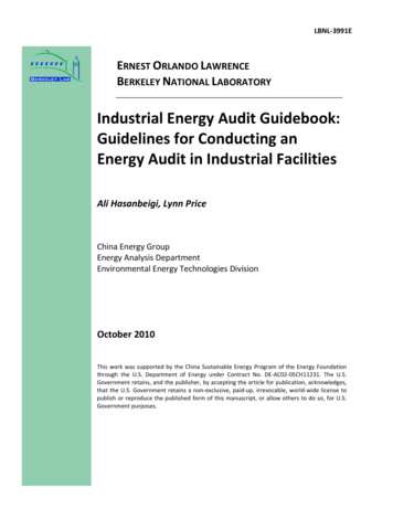
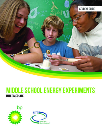
Type0OTENTIAL BENEÇTSPotential drawbacksDiscretecomponentEESSWider choice of interface options.Greater reliance on the designerand installer of the systemduring the installation to correctlyspecify, source, install, test andcommission.Easier to make the installationbespoke to needs.Freedom to choose productsfrom different manufacturers.The design and commissioning#AN BE SUITABLE FOR PROÇLE SHIFTING stages would require moreand grid-demand support.documentation.The designer and installer need tocompile operation andmaintenance information toensure that the 'as-delivered'system can be safely operatedand maintained.The designer and installer needto understand the user's loadPROÇLE TO PROPERLY CONÇGURE AND commission the system to deliverMAXIMUM EFÇCIENCY UPS orCan be distributed throughoutbattery backup the electrical installation, closer tosystemthe point(s) of use or on selectedcircuits, to provide power in theevent of a fault within other partsof the electrical installation, aswell as loss of the grid supply.Costly for smaller-scalecommercial users and indwellings.Generally independent of locallygenerated energy.Typically not suitable forGRID DEMAND SUPPORT OR PROÇLEshifting.3.2 Purpose, load profile, charge anddischarge cyclesIn order to select an appropriate EESS it is essential to understand its purpose andbenefits with respect to:(a)(b)(c)(d)the power/energy that will be used by the installation;variations in demand;renewable/local generation sources; andgrid connection constraints.Many systems will be used to modify the amount of energy consumed from the grid atcertain times. Figure 3.1 shows what the energy demand and energy generation in aninstallation with solar PV might look like.6 The Institution of Engineering and Technology
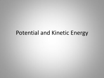
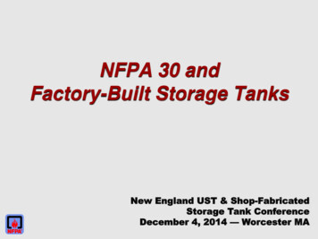
T Figure 3.1Illustration of energy demand/generation in an installation with solar PV;courtesy of G Kenyon Technology Ltd.Energy used in the installationEnergy available from solar PVIllustrative onlyEnergy00.0004.0008.0012.0016.0020.00Time of dayGrid meetingpower demand ofinstallationSolar PV exportingpower and meetingpower demand ofinstallationGrid meetingpower demand ofinstallationIn Figure 3.2, an EESS has been employed to modify the energy used from the grid inthe following ways:(a) the energy generated by the solar PV system is used solely by the installationitself, which reduces the maximum demand from the grid ('peak lopping'), whichmay have the overall benefit of reducing grid demand at peak periods.(b) energy from the grid is used at off-peak periods (perhaps at a lower energyrate) to charge the EESS batteries for later use before the solar PV system hasstarted to generate power. Known as 'load profile shifting' or 'time shifting', thistechnology provides the benefit of cheaper power and the ability to use morefrom renewable sources of efficient energy, whilst enabling traditional gridgeneration technologies to be used at periods when the demand is less. The Institution of Engineering and Technology7
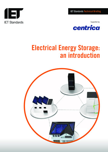
T Figure 3.2Illustration of how energy storage systems can bring cost benefits bymodifying the load profile; courtesy of G Kenyon Technology Ltd.Energy used in the installationEnergy available from solar PVEnergy taken from GridEnergyIllustrative only00.0004.0008.0012.0016.0020.00Time of dayGrid energyused tocharge EESSbatteries ‘offpeak’EESSbatteriesdischargingSolar PV energy usedto charge EESSbatteries, meet theinstallation demand,and export anysurplusEESSbatteriesdischargingGrid powersupplementsdemandCertain types of renewable generation have seasonal variations in their effectiveness.For example, during the UK's winter months, solar PV systems only generate a fractionof the power they generate during the summer months. In winter, there will thereforebe more reliance of the EESS on time shifting grid power to off-peak periods to reduceenergy costs, as the energy available from solar PV arrays may be insufficient to meetinstallation demands and/or fully charge batteries.3.3 Main system componentsFigure 3.3 illustrates in schematic form the components that may be found in an EESS.Not all systems will have all of the components but they are shown so that the conceptsbeing discussed in this Technical Briefing can be illustrated.In particular, the EESS controller may comprise several components in a systemconstructed from discrete components and include components and safety features,such as:(a) double-pole switched isolation for the grid supply as in a typical solar PVinstallation complying with BS 7671;(b) isolation transformers;(c) d.c. to d.c. converters;(d) a.c. to d.c. converters; and(e) d.c. to a.c. inverters.The overall efficiency of the EESS depends on many factors including the efficiency ofthe EESS controller. This is affected by power losses in operating the control electronicsfor charge, discharge and switching controls, and any losses associated with voltagetransformation.8 The Institution of Engineering and Technology
The EESS controller may be connected to sources of energy via a.c. coupling or d.c.coupling. Necessarily, the connection to the grid supply will be via a.c. coupling.Coupling to other energy sources at standard voltages and frequencies defined in BS EN50160 provides ready compatibility in the ratings of devices. However, the designer muststill determine whether any electronic converters at the output of the energy source arecompatible with a.c. to d.c. converters within the EESS controller. This is because theconverters often operate using switched-mode design, and the waveforms from theswitching devices may be incompatible.d.c. coupling of energy sources, and indeed loads, may afford a lower-cost, more energyefficient solution, even where d.c. to d.c. converters are used to change the d.c. voltage,as these are often more efficient than a.c. to d.c. and d.c. to a.c. converters. Whilst d.c. tod.c. converters also operate with switched mode circuitry, there are fewer compatibilityproblems due to the simpler way in which the d.c. output from the converter can besmoothed.T Figure 3.3Overview of system components; courtesy of G Kenyon Technology Ltd.Generation(a.c. output) e.g. windPublicsupplyGeneration(d.c. output) e.g. solar PVIndependent meansof earthing (if needed)Gridd.c. coupledgenerationa.c. SS controllerBatteryOn-Grida.c. controlOff-Grida.c. controlOn-Gridd.c. controla.c. power distributionNon-criticalloadsCharge controland monitoringd.c. power distributionCriticalloadsNon-criticalloadsLow power ‘critical’a.c. circuits, e.g.lighting,communications etc.Remaining a.c.circuits in theinstallationOff-Gridd.c. controlCriticalloadsLow power ‘critical’d.c. circuits, e.g.lighting,communications etc.Remaining d.c.circuits in theinstallation The Institution of Engineering and Technology9
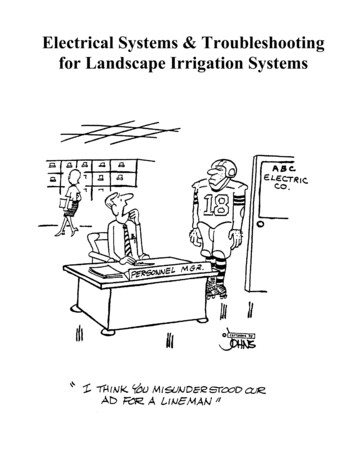
3.4 The storage technologyThe scope of this Technical Briefing is limited to electrochemical storage technologies, asthis is the predominant technology that is currently available to meet the needs of EESS.Amongst other technologies, the following types of cell are currently popular for EESS:(a) lead-acid type batteries. These include acid-gel and valve-regulated lead-acid(VRLA) types.(b) lithium-ion batteries.(c) flow batteries.This list is not exhaustive. Further information on batteries will be available in the IETCode of Practice for Electrical Energy Storage Systems.T Figure 3.4Typical batteries3.4a Lithium-ion battery courtesy LG3.4b VLA battery courtesy BAE PVS10 The Institution of Engineering and Technology
3.4c VRLA battery courtesy YUASAThese battery types are compared in Table 3.2 and other types of batteries are emergingas the result of research. Designers who are specifying installations should keep abreastof developments in storage technologies to ensure that the optimum battery types areselected.The capacity of a battery is normally stated in ampere-hours (Ah). However, to understandhow much energy is stored requires knowledge of the battery voltage. If we have a 100 Ah12 V battery, this stores up to 1,200 Wh, or 1.2 kWh. Batteries may be connected inseries or in parallel to increase the capacity, provided that this is supported by thecharge management system to ensure that there are no overvoltages/overcurrentsduring charging.Battery manufacturers typically recommend that the capacity of the battery is specifiedto be greater than the initial design capacity, by between 15 % and 50 %, depending onthe battery technology, the maintenance replacement lifecycle, and the environmentalconditions (chiefly temperature) in which the batteries will be used.The key considerations when selecting the batteries are:(a) capacity: check the battery capacity is adequate for the anticipated dischargerequirement, whilst not too great so as to prevent complete charging. Incompletecharging can cause the battery to fail early and some battery types are unsuitedto complete discharge.(b) suitability: ensure that batteries are matched to the charge/dischargemanagement components in the configuration in which they will operate.(c) compatibility with environment: check that the batteries are suited to theenvironmental conditions and the facilities available to house the EESS (seeSection 3.5), including the ability to safely install, maintain and decommission.(d) disposal: batteries or their components will need to be disposed of at the endof their life, without damaging the environment, and in accordance with relevantlegislation (Waste Batteries and Accumulators Regulations 2009). The Institution of Engineering and Technology11
TTable 3.2Comparison of lead-acid (VLA and VRLA), lithium-ion and flow batteries;courtesy of G Kenyon Technology ead-acid(VLA)Oldest battery type, incommercial use for over100 years.Can deliver highcurrents.Uses lead, whichis harmful to theenvironment in disposaland potentially harmfulto health for maintainers.Operate from the actionof lead and lead oxideelectrodes, typicallywith sulphuric acidelectrolyte.Easily recycled throughexisting channels.Not suited to completedischarge, which mayirreversibly damage thebattery.Charges slowly.Releases hydrogen gaswhen charging, so freshair ventilation is required.Electrolyte maintenanceis required. The acidelectrolyte is caustic.VRLASometimes knownas 'sealed' batteriesbecause they require nomaintenance.Principally, there aretwo varieties: 'acid-gel'electrolyte or absorbentglass mat. Bothoperate on a similarelectrochemical principalto VLA.No maintenancerequired.Can deliver highcurrents.'Deep cycle' versionsare available thatpermit more completedischarge than VLA.Less susceptible toelectrolyte leakage ifbroken.Uses lead, whichis harmful to theenvironment in disposal.Overcharging candamage the battery.In overcharge or faultconditions, certain VRLAbatteries may producehydrogen, and fresh airventilation is thereforerequired.Easily recycled throughexisting channels.Lithium-ion A more recenttechnology, these(Li-Ion)batteries charge anddischarge by themovement of lithiumions between theelectrodes.Originally foundpopularity in theportable consumer andbusiness electronicproducts market;advances in productsafety and overallperformance are nowbeing driven by theiruse in the automotiveelectric vehicle market.Li-Ion batteries needprotection systemsto prevent thermalrunaway.12Lighter, having between2 and 5 times betterstorage capacity in termsof weight of the batterythan lead-acid types.Between 10 and 20times more chargedischarge cyclesthan lead-acid types,making them moresuitable for frequentcharge-discharge usesassociated with loadprofile shifting anddomestic generationtechnologies such assolar PV.Without protectionsystems, can be subjectto thermal runaway.Not easily recyclable atpresent.Mechanical damage maylead to thermal runawayif not adequatelyprotected against.Operational life similarto VRLA. The Institution of Engineering and Technology
esA very recenttechnology, where thebattery operatessomewhat similarly to areversible fuel cell, or alarge battery where theelectrolyte is stored intanks and pumped pastelectrodes, toincrease storagecapacity without increasing electrode dimensions.See Figure 3.5.Increasing storagecapacity does not meana corresponding increasein short-circuit current.Requires energy todrive pumps. This ispotentially far lesssignificant for largerEESS, but may presentinefficiencies for smallerEESS. Note: Flowbatteries therefore maybe better suited tocommunity EESS thanindividual dwellings.TThermal conditionsin the cell are bettermanaged as flowingelectrolytes remove heatfrom the cell.Potentially longer servicelife.Can be tailored for verylarge EESS.Substances used incertain flow batteries,such as vanadium,may be harmful to theenvironment in disposal.Figure 3.5 Key components of a flow battery system; courtesy of G Kenyon TechnologyLtd.Flow cellMany cells may be connected to form a flow batteryIon selectivemembraneElectrolyte tankElectrolyte nEESS controllerLoads The Institution of Engineering and Technology13
3.5 Facilities3.5.1 GeneralOne of the key factors in deciding whether to install an EESS is whether there is asuitable and safe location for the system and its components. Considerations for facilitiesand the physical environment in which the EESS will be housed must be made, asdiscussed below.3.5.2 Floor/wall loadingBattery sets of all types, in particular, can be heavy, and it is therefore important to assesswhere to mount equipment. This assessment will include consideration of the capabilityof the floors and/or walls to support it.3.5.3 Temperature and ventilationCurrent battery technologies suited for EESS perform at their optimum when charged,stored and discharged within a certain temperature band, although the actual temperatureband depends on the battery technology and can vary between manufacturer and model.As an example, typical storage performance characteristics with respect to temperaturefor typical lead-acid battery types (VLA/VRLA) operating in standby power mode areillustrated in Figure 3.6.The lifecycle of other technologies such as Li-Ion may be more complex, with thecapacity over the life depending on:(a)(b)(c)(d)(e)(f)(g)the physical arrangement inside the battery;the particular electrolyte/electrode chemistry;depth of discharge;temperature during the charging period;temperature during the storage period;temperature during discharge; andthe duration of the storage period.Many Li-Ion cells designed for use in EESS contain in-built safety monitoring to preventthermal runaway; it is also important for the charge/discharge management system toclosely manage the charge/discharge cycles depending on temperature so that batterylife can be optimised.In the UK, the primary considerations are to help protect the battery from the extremesof winter and summer temperatures. Better performance can be obtained in locationswhere the temperature can be maintained within a limited range (dependent on typeand manufacturer, but often 18 C to 25 C for lead-acid and Li-Ion types). With largercapacity energy storage installations, thermal management may prove cost-effectivefor improving performance and increasing time between maintenance replacements ofbatteries of certain technologies.Certain battery technologies, such as lead-acid and VRLA types, require fresh airventilation to prevent accumulation of hydrogen in explosive concentrations. Hydrogenmay be produced during faults on the battery or charger. The air refresh rate shouldbe calculated in line with the guidance of BS EN 50272 and any further informationprovided by manufacturers.14 The Institution of Engineering and Technology
T Figure 3.6 Storage performance life of typical lead-acid/VRLA batteries in standby mode;Paul de Montigny, Saskpower, via www.mpoweruk.com/life.htmTypical lead-acid battery capacity versusage for different operating temperatures115%150C250C105%350CBatterycapacity 95%(% Rated)85%75%1611162126313641Battery age (Yrs)3.5.4 Access for maintainabilityCertain properties of the location are important to ensuring that the energy storageequipment is safe to maintain, for example:(a) workspace and access to equipment should be adequate to prevent electrical andother dangers during installation, maintenance and decommissioning.(b) means of isolation and other protection should be clearly identifiable and readilyaccessible to the persons who need to access them.(c) individual components that are heavy and require regular maintenancereplacement (for example, certain batteries) should be located at a suitableheight for lifting into and out of enclosures or housings. Ideally, there should beadequate room to manoeuvre the batteries without the maintainer having to twistas part of the removal or replacement.(d) lighting should be adequate for installation and maintenance activities. Thereshould be room to utilise temporary lighting regardless of whether lighting hasbeen permanently installed, to enable work to be undertaken when power isdisconnected.3.5.5 Fire detection and suppressionThe fire risk assessment for the premises should be consulted and, where necessary,revisited, when designing and installing an EESS. In addition to considering the effects ofthe EESS itself on the fire risk assessment, and any additional fire detection requirements,manufacturers and designers should be consulted to ensure that any fire suppressiontechnologies in use in the location, or recommended by the fire risk assessment, arecompatible with all of the EESS components.The selection of inappropriate firefighting equipment or fire suppression system for aparticular battery type may have devastating results. The Institution of Engineering and Technology15
3.5.6 Warnings and signsWarning signs should be provided where necessary to:(a) the general public and untrained staff, flagging that only trained and competentpersons should maintain the system, and advising of the principal hazards ofelectric shock and any risks associated with the charging and battery technology(for example, corrosive chemicals or impeded ventilation).(b) installers, maintainers, decommissioners and emergency services to flag anyfurther hazards, such as the fact that there is stored energy (batteries) that cannotalways be fully isolated and, where necessary, multiple means of isolation beingclearly identifiable.Signs used should comply with the Health and Safety (Safety Signs and Signals)Regulations and relevant standards such as BS EN ISO 7010.Further signs may be required to indicate the means by which the installation (orparts of it) can be safely isolated and to indicate the voltage ratings of equipment andsub-assemblies where these are unexpectedly different from the normal supply voltage.16 The Institution of Engineering and Technology
1SECTION 4Electrical arrangements4.1 TypeThe low voltage grid supply in the UK operates at voltages and frequencies harmonizedby BS EN 50160, i.e. at 230/400 V 50 Hz a.c. (or 230 V 50 Hz a.c. for three-wire threephase systems earthed at one of the phases).The output voltage available from local generation depends on the technolog
energy storage systems, covering the principle benefits, electrical arrangements and key terminologies used. The Technical Briefing supports the IET’s Code of Practice for Electrical Energy Storage Systems and provides a good introduction to the subject of electrical