Transcription
EET1122/ET162 Circuit AnalysisAcknowledgementI want to express my gratitude to Prentice Hall giving me the permissionto use instructor’s material for developing this module. I would like tothank the Department of Electrical and Telecommunications EngineeringTechnology of NYCCT for giving me support to commence andcomplete this module. I hope this module is helpful to enhance ourstudents’ academic performance.Sunghoon JangIntroductionElectrical and TelecommunicationsEngineering Technology DepartmentProfessor JangPrepared by textbook based on “Introduction to Circuit Analysis”by Robert Boylestad, Prentice Hall, 10th edition.Introduction – The Electrical/Electronics EngineeringOUTLINES¾The growing sensitivity to the technologies on Wall Street is clearevidence that the electrical/electronics industry is one that will have asweeping impact on future development in a wide range of areas thataffect our life style, general health, and capabilities.Introduction to Electrical Engineering¾ A Brief History Semiconductor Device¾ Units of Measurement Analog & Digital Signal Processing¾ Systems of Units Telecommunications Biomedical Engineering¾ Operation of a Scientific Calculator Fiber Optics & Opto-Electronics Integrated Circuit (IC)¾ Significant FiguresKey Words: Electrical Engineering, Units, Powers, CalculatorET162 Circuit Analysis – IntroductionBoylestad2Figure 1.1 Computer chip onfinger. (Courtesy of Intel Corp.)ET162 Circuit Analysis – IntroductionBoylestad31
Introduction – A Brief HistoryUnits of MeasurementThe numerical value substituted into an equation must haveThe unit of measurement specified by the equationExamples1 mi 5280 ft4000 ft 0.7576 mi1 min 0.0167 hv d0. 7576mi 45. 73 mi/ ht0. 0167hFIGURE 1.2 Time charts: (a)long-range;long-range; (b) expanded.expanded.ET162 Circuit Analysis – IntroductionBoylestad4ET162 Circuit Analysis – IntroductionBoylestad5Systems of UnitsSystems of UnitsThe English system is based on a single standard, the metric issubdivided into two interrelated standards: the MKS and the CGS.EnglishLength: Yard (yd)Mass: SlugForce: PoundTemperature: Fahrenheit ( F)Energy: Foot-pound (ft-lb)Time: Seconds (s)ET162 Circuit Analysis – IntroductionMetricLength: Meter (m)Mass: Kilogram (kg)Force: Newton (N)Temperature: Kelvin (K)Energy: Joule (J)Time: Seconds (s)Boylestad6FIGURE 1.3 Comparison of2
Powers of TenSignificant Figures, Accuracy, and Rounding offIn the addition or subtraction of approximate numbers, the entry with thelowest level of accuracy determines the format of the solution.For the multiplication and division of approximate numbers, the result hasthe same number of significant figures as the number with the latest numberof significant figures.1 10010 101100 1021000 103Ex. 1-2Ex. 1-1 Perform the indicated operations with the followingapproximate numbers and round off to the appropriate level of accuracy.a.b.c.d.e.f.11 10 3 310001011 10b. 0 .0000110 5532.6 4.02 0.036 536.656 536.70.04 0.003 0.0064 0.0494 0.054.632 2.4 11.1168 113.051 802 2446.902 24501402/6.4 219.0625 2200.0046/0.05 0.0920 0.09ET162 Circuit Analysis – IntroductionBoylestada.8ET162 Circuit Analysis – IntroductionEx. 1-3Boylestad9When adding or subtracting numbers in a powers-of-ten format, be sure thatthe power of ten is the same for each number. Then separate the multipliers,perform the required operation, and apply the same power of ten to theresults.Ex. 1-4100, 000 10 5 10 ( 5 2 ) 10 310010 2)1000 10 3 b.10 ( 3 ( 4 ) 10 ( 3 4 ) 10 7 40 .000110a.Ex. 1-6a. 6300 75,000 (6.3)(1000) (75)(1000) 6.3 103 75 103 (6.3 75) 103 81.3 103a. 0.00096 – 0.000086 (96)(0.00001) – (8.6)(0.00001) 96 10-5 – 8.6 10-5 (96 – 8.6) 10-5 87.4 10-5Ex. 1-5a. (100)4 (102)4 10(2)(4) 108b. (1000)-2 (103)-2 10 (3)(-2) 10-6c. (0.01)-3 (10-2)-3 10(-2)(-3) 106Boylestad 5Basic Arithmetic Operationsa. (1000)(10,000) (103)(104) 10(3 4) 107b. (0.00001)(100) (10-5)(102) 10 (-5 2) 10-3ET162 Circuit Analysis – Introduction1/10 0.1 10-11/100 0.01 10-21/1000 0.001 10-31/10,000 0.0001 10-410ET162 Circuit Analysis – IntroductionBoylestad113
Ex. 1-7Ex. 1-8Ex. 1-9a. (0.0002)(0.000007) [(2)(0.0001)] [(7)(0.000001)] (2 10-4)(7 10-6) (2)(7) (10-4)(10-6) 14 10-10a. (340,000)(0.00061) (3.4 105)(61 10-5) (3.4)(61) (105)(10-5) 207.4 100 207.4a. 0.00047 47 10 5 47 10 5 3 23.5 10 2 3 2 10 0.0022 10b.690 ,00069 10 4 69 10 4 5.31 1012 0.00000013 13 10 8 13 10 8 Calculators and Order of Operationa. (0.00003)3 (3 10-5)3 (3 10-5)3 (3)3 10-15b. (90,800,000)2 (9.08 107)2 (9.08)2 (107)2 82.4464 1014ET162 Circuit Analysis – IntroductionBoylestad12ET162 Circuit Analysis – IntroductionBoylestad13HW 1-26 Perform the following conversions:a. 1.5 min to secondsb. 0.04 h to secondsc. 0.05 s to microsecondsd. 0.16 m to millimeterse. 0.00000012 s to nanosecondsf. 3,620,000 s to daysHomework 1: 12, 14, 24, 26, 41, 42, 43ET162 Circuit Analysis – IntroductionBoylestad144
EET1122/ET162 Circuit AnalysisCurrent and VoltageElectrical and TelecommunicationsEngineering Technology DepartmentOUTLINES Resistance and Conductance Ohmmeters Current and Voltage Ammeters and VoltmetersProfessor JangKey Words: Resistance, Ohmmeter, Current, Voltage, Ammeter, VoltmeterPrepared by textbook based on “Introduction to Circuit Analysis”by Robert Boylestad, Prentice Hall, 10th edition.ET162 Circuit Analysis –Current and VoltageBoylestad2BoylestadAt a fixed temperature of 20 C (room temperature), the resistance isrelated to the other three factor byIntroduction to ResistanceThe flow of charge through any materialencounters an opposing force similar inmany aspect to mechanical friction. Thisopposition, due to the collisions betweenelectrons and other atoms in the material,which converts electrical energy intoanother form of energy such as heat, iscalled the resistance of the material. Theunit of measurement of resistance is the ohm(Ω).ET162 Circuit Analysis –Current and VoltagelR ρA(ohms, Ω)ρ : resistivity of the sample (CM-ohms/ft at T 20 C)l : the length of the sample (feet)A : cross-sectional area of the sample (circular mils (CM))Figure 1.1 Resistance symbol andnotation.FIGURE 1.2 Factors affecting theresistance of a conductor.3ET162 Circuit Analysis –Current and VoltageBoylestad41
Types of Resistors – Fixed ResistorsResistance: Circular WiresFor two wires of the same physical size at the same temperature, the higher the resistivity (ρ), the more the resistanceResistors are made in many forms, but all belong in either of two groups: fixed orvariable. The most common of the low-wattage, fixed-type resistors is the moldedcarbon composition resistor. the longer the length of a conductor, the more the resistance the smaller the area of a conductor, the more the resistance the higher the temperature of a conductor, the more the resistanceFIGURE 1.3 Cases in which R2 R1. For each case, all remaining parameters thatcontrol the resistance level are the same.ET162 Circuit Analysis –Current and VoltageBoylestad5FIGURE 1.3 Fixed composition resistor.The relative sizes of all fixed and variableresistors change with the power rating,increasing in size for increased power ratings inorder to withstand the higher currents anddissipation losses.FIGURE 1.4 Fixed compositionresistors of different wattage ratings.ET162 Circuit Analysis –Current and Voltage6BoylestadColor Coding and Standard Resistor ValuesTypes of Resistors – Variable ResistorsVariable resistors have resistance that can be varied by turning a dial, knob,screw, or whatever seems appropriate for the application.A whole variety of resistors are large enough to have their resistance inohms printed on the casing. However, some are too small to have numbersprinted on them, so a system of color coding is used.FIGURE 1.6 Color coding of fixed molded composition resistor.Band 1-2FIGURE 1.5 Potentiometer: (a) symbol: (b) & (c) rheostatconnections; (d) rheostat symbol.ET162 Circuit Analysis –Current and VoltageBoylestad7The first and second bandsrepresent the first and seconddigits, respectively. The thirdband determines the power-often multiplier for the first twodigits. The fourth band is themanufacture’s tolerance. Thefifth band is a reliability factor,which gives the percentage ofET162 Circuit Analysis – Voltage and Currentfailureper 1000 hours of use.Band 3Band 4Band 50 Black1005% Gold1% Brown1 Brown10110% Silver0.1% Red2 Red10220% No band0.01% Orange3 Orange1034 Yellow1045 Green1056 Blue1067 Violet1078 Gray1089 White109Table 1 Resistor colorBoylestadcoding.0.01% Yellow82
Ex. 1-1 Find the range in which a resistor having the following color bands mustexist to satisfy the manufacturer’s tolerance:ConductanceThe quantity of how well the material will conduct electricityis called conductance (S).b.1st Band2nd Band3rd Band4th Band5th BandOrangeWhiteGoldSilverNo color3910–1 0.1 10%a. 82Ω 5% (1% reliability)aSince 5% of 82 4.10, the resistor should be withinthe range of 82Ω 4.10Ω, or between 77.90 and 86.10Ω.G 1RAG ρ l(siemens, S)Indicating that increasingthe area or decreasingeither the length or theresistivity will increase theConductance.(S)b. 3.9Ω 10% 3.9Ω 0.39ΩThe resistor should be somewhere between 3.51 and 4.29Ω.ET162 Circuit Analysis –Current and VoltageBoylestad9Ex. 1-2 What is the relative increase or decrease in conductivity of a conductor ifthe area is reduced by 30% and the length is increased by 40%? The resistivity isfixed.G Aiρ i li10BoylestadOhmmetersThe ohmmeter is an instrument used to perform the following tasksand several other useful functions.1. Measure the resistance of individual or combined elements2. Direct open-circuit (high-resistance) and short-circuit (lowresistance) situations(siemens, S)with the subscript i for the initial value. Using the subscript n fornew value :Gn ET162 Circuit Analysis –Current and Voltage3. Check continuity of network connections and identify wires of amulti-lead cable4. Test some semiconductor devices0.70 AiAn0.70 Ai0.70 0.5 Giρ nln ρ i (1.4 li ) 1.4 ρ i li 1.4 GiET162 Circuit Analysis –Current and VoltageBoylestad11FIGURE 1.7 Measuring the resistance ofa single element.FIGURE 1.8 Checking the continuity ofa connection.3
Ex 1-3 In Figure, three conductors of different materials are presented.a. Without working out the numerical solution, determine which section wouldappear to have the most resistance. Explain.b. Find the resistance of each section and compare with the result of (a) (T 20 C)VoltageThe voltage across an element is the work (energy) required to movea unit positive charge from the ̶ terminal to the terminal. The unitof voltage is the volt, V.A potential difference of 1 volt (V) exists between two points if 1 joul(J) of energy is exchanged in moving 1 coulomb (C) of chargebetween the two points.a. Rsilver Rcopper Raluminuml (9.9)(1 ft ) 9.9 Ω1CMAl (10.37 )(10 ft ) 1.037 ΩCopper : R ρ 100CMAl (17 )(50 ft ) 0.34 ΩAlu min um : R ρ A 2500CMSilver : R ρET162 Circuit Analysis –Current and VoltageWV Q13BoylestadEx. 1-4 Find the potential difference between two points in an electrical systemif 60 J of energy are expended by a charge of 20 C between these two points.V W 60 J 3VQ 20 CV voltage (V)Q coulombs (C)W potential energy (J)ET162 Circuit Analysis –Current and VoltageFIGURE 1.9 Defining the unit of measurement forvoltage.Boylestad14Fixed (dc) SuppliesThe terminology dc is an abbreviation for direct current, whichencompasses the various electrical systems in which there is aunidirectional (“one direction”) flow of charge.DC Voltage SourcesEx. 1-5 Determine the energy expended moving a charge of 50 μC through apotential difference of 6 V.(In general, the potential difference betweentwo points is determined by:Dc voltage sources can be divided into three broad categories:(1)Batteries (chemical action), (2) generators (electro-mechanical),and (3) power supplies (rectification).)W Q V 50 10 6 (6 V ) 300 10 6 J 300 µ JET162 Circuit Analysis –Current and VoltageBoylestadFIGURE 1.11Terminalcharacteristics: (a)ideal voltagesource; (b) idealcurrent source.FIGURE 1.10 Symbolfor a dc voltage source.15ET162 Circuit Analysis –Current and VoltageBoylestad164
CurrentThe electrical effects caused by charges in motion depend on the rateof charge flow. The rate of charge flow is known as the electricalcurrent. With no external forces applied, the net flow of charge in aconductor in any direction is zero.If 6.242 1018 electrons (1 coulomb) pass through the imaginaryplane in Fig. 2.9 in 1 second, the flow of charge, or current, is said tobe 1 ampere (A).Ch arg e / electron Qe 1C 1.6 10 19 C186.242 10The current in amperes can now be calculated using the followingequation:Q I t (coulomb, C)I QtI amperes (A)Q coulombs (C)t seconds (s)andt FIGURE 1.12 Basic electrical circuit.ET162 Circuit Analysis –Current and Voltage17BoylestadEx. 1-6 The charge flowing through the imaginary surface of Fig. 1-12 is 0.16 Cevery 64 ms. Determine the current in ampere.I 3Q0.16C160 10 C 2.50 A 3t 64 10 s64 10 3 sET162 Circuit Analysis –Current and VoltageQI(sec onds, s)18BoylestadAmmeters and VoltmetersIt is important to be able to measure the current and voltage levels ofan operating electrical system to check its operation, isolatemalfunctions, and investigate effects. Ammeters are used to measurecurrent levels while voltmeters are used to measure the potentialdifference between two points.Ex. 1-7 Determine the time required for 4 1016 electrons to pass through theimaginary surface of Fig. 1.12 if the current is 5 mA.1C Q 4 1016 electron 186.242 10electrons 0.641 10 2 C 0.00641 C 6.41 mCQ 6.41 10 3 C I5 10 3 A 1.282 st FIGURE 1.13 Voltmeter and ammeter connection for an up-scale ( ) reading.ET162 Circuit Analysis –Current and VoltageBoylestad19ET162 Circuit Analysis – Voltage and CurrentBoylestad205
EET1122/ET162 Circuit AnalysisAcknowledgementI want to express my gratitude to Prentice Hall giving me the permissionto use instructor’s material for developing this module. I would like tothank the Department of Electrical and Telecommunications EngineeringTechnology of NYCCT for giving me support to commence andcomplete this module. I hope this module is helpful to enhance ourstudents’ academic performance.Sunghoon JangOhm’s LawElectrical and TelecommunicationsEngineering Technology DepartmentProfessor JangPrepared by textbook based on “Introduction to Circuit Analysis”by Robert Boylestad, Prentice Hall, 10th edition.Introduction to Ohm’s LawOUTLINES¾ IntroductionOhm’s law clearly reveals thata fixed resistance, the greaterthe voltage across a resistor,the more the current, the morethe resistance for the samevoltage, the less the current.to Ohm’s Law¾ Plotting Ohm’s LawE(amperes, A)RE I R (volts, V )ER (ohms, Ω)II ¾ PowerVI RKey Words: Ohm’s Law, Current, Voltage, PowerFigure 4.1 Basic Circuit.ET162 Circuit Analysis – Ohm’s LawBoylestad2ET162 Circuit Analysis – Ohm’s LawBoylestad31
Ex. 4-1 Determine the current resulting from the application of a 9-V batteryacross a network with a resistance of 2.2 Ω.I For an isolated resistive element, the polarity of the voltage dropis as shown in Fig. 4.2(a) for the indicated current direction. Areversal in current will reverse the polarity, as shown in Fig.4.2(b). In general, the flow of charge is from a high ( ) to a low (–)potential.9VE 4.09 AR 2.2 ΩEx. 4-2 Calculate the resistance of a 60-W bulb if a current of 500 mA resultsfrom an applied voltage of 120 V.R 120 VE 240 ΩI 500 10 3 AFIGURE 4.2 Defining polarities.BoylestadET162 Circuit Analysis – Ohm’s Law45Plotting Ohm’s LawEx. 4-3 Calculate the current through the 2-kΩ resistor of Fig. 4.3 if the voltagedrop across it is 16 V.Graph, characteristics, plots play an important role in every technicalfield as a mode through which the broad picture of the behavior orresponse of a system can be conveniently displayed. It is thereforecritical to develop the skills necessary both to read data and to plotthem in such a manner that they can be interpreted easily.16 VEI 8 mAR 2 10 3 ΩFIGURE 4.3 Example 4.3For most sets of characteristicsof electronic devices, the currentis represented by the verticalaxis, and the voltage by thehorizontal axis, as shown in Fig.4.5.Ex. 4-4 Calculate the voltage that must be applied across the soldering iron ofFig. 4.5 to establish a current of 1.5 A through the iron if its internal resistance is80 Ω.E I R (15. A)(80 Ω) 120 VET162 Circuit Analysis – Ohm’s LawBoylestadET162 Circuit Analysis – Ohm’s LawFIGURE 4.4 Example4.4BoylestadFIGURE 4.5 Plotting Ohm’slaw6ET162 Circuit Analysis – Ohm’s LawBoylestad72
If the resistance of a plot is unknown, it canbe determined at any point on the plot sincea straight line indicates a fixed resistance. Atany point on the plot, find the resultingcurrent and voltage, and simply substituteinto following equation:VRdc IEx. 4-5 Determine the resistance associated with the curve of Fig. 4.8 usingequations from previous slide, and compare results.At V 6 V , I 3 mA, andThe equation states that by choosing a particular V, one can obtainthe corresponding I from the graph, as shown in Fig. 4.6 and 4.7,and then determine the resistance.Rdc 6VV 2 kΩI3 mAAt the int erval between 6 V and 8 V ,R R FIGURE 4.6 Demonstrating on an I-V plot that theless the resistance, the steeper is the slope V IFIGURE 4.8 Example 4.5.FIGURE 4.7ET162 Circuit Analysis – Ohm’s LawPower is an indication of how much work can be done in a specifiedamount of time, that is, a rate of doing work. Since converted energy ismeasured in joules (J) and time in seconds (s), power is measured injoules/second (J/s). The electrical unit of measurement for power is thewatt (W), defined by1 watt (W) 1 joules/second (J/s)WtBoylestadEq. 2PowerP V 2 V 2 kΩ I 1 mA( watts, W , or joules / sec ond , J / s)2 V VP V I V R R9Eq. 3( watts) P V I ( I R) I I 2 R (watts)The result is that the power absorbed by the resistor of Fig. 4.9 can be founddirectly depends on the information available.Power can be delivered or absorbed as defined by the polarity of the voltageand direction of the current. For all dc voltage sources, power is beingdelivered by the source if the current has the direction appearing in Fig. 4.10(a).1 horsepower 746 wattsP W Q VQQ V V I ( watts) where I ttttET162 Circuit Analysis – Ohm’s LawBoylestadEq. 110FIGURE 4.9 Defining the power to aresistive element.ET162 Circuit Analysis – Ohm’s LawFIGURE 4.10 Battery power: (a) supplied; (b) absorbed.Boylestad113
Ex. 4-8 The I-V characteristics of a light bulb are powered in Fig. 4.12. Note thenonlinearity of the curve, indicating a wide range in resistance of the bulb withapplied voltage as defined by the earlier discussion. If the rated voltage is 120 V,find the wattage rating of the bulb. Also calculate the resistance of the bulbunder rated conditions.Ex. 4-6 Find the power delivered to the dc motor of Fig. 4.11.P V I (120V )(5 A) 600W 0.6 kWAt 120V , I 0.625 AP V I (120V )(0.0625 A) 75WFIGURE 4.11 Example 4.6.At 120V , R V 120V 192 ΩI 0.625 AEx. 4-7 What is the power dissipated by a 5-Ω resistor if the current is 4 A?P I2R (4 A)2(5 Ω) 80 WFIGURE 4.12 The nonlinear I-V characteristics ofa 75-W light bulb.BoylestadET162 Circuit Analysis – Ohm’s Law12PRorI 13a. Pi EI (120V )(2.4 A) 288 WP(ampere)RV2P V 2 PR or V RBoylestadHW 4-52 A stereo system draws 2.4 A at 120 V. The audio output power is 50 W.a. How much power is lost in the form of heat in the system?b. What is the efficiency of the system?Sometimes the power is given and the current or voltage must bedetermined.P I 2R I 2 ET162 Circuit Analysis – Ohm’s LawPi Po Plost , Plost Pi P0 288 W 50 W 238 Wb. η % PR (volts)P050W 100% 100% 17.36%Pi288WEx. 4-9 Determine the current through a 5-kΩ resistor when the power dissipatedby the element is 20 mW.I P R20 10 3 W 4 10 6 2 10 3 A 2 mA5 10 3 ΩET162 Circuit Analysis – Ohm’s LawBoylestadHomework 4: 2, 4, 6, 8, 20, 24, 25, 26, 49, 5214ET162 Circuit Analysis – Ohm’s LawBoylestad154
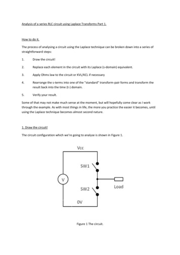
EET1122/ET162 Circuit AnalysisAcknowledgementI want to express my gratitude to Prentice Hall giving me the permissionto use instructor’s material for developing this module. I would like tothank the Department of Electrical and Telecommunications EngineeringTechnology of NYCCT for giving me support to commence andcomplete this module. I hope this module is helpful to enhance ourstudents’ academic performance.Sunghoon JangSeries CircuitsElectrical and TelecommunicationsEngineering Technology DepartmentProfessor JangPrepared by textbook based on “Introduction to Circuit Analysis”by Robert Boylestad, Prentice Hall, 10th edition.Series Circuits - IntroductionOUTLINESTwo types of current are available to the consumer today. One is directcurrent (dc), in which ideally the flow of charge (current) does notchange in magnitude with time. The other is sinusoidal alternatingcurrent (ac), in which the flow of charge is continually changing inmagnitude with time.¾ Introduction to Series Circuits¾ Kirchhoff’s Voltage Law¾ Voltage Divider RuleV (volt) E (volt)¾ Interchanging Series Elements¾ Series Circuits – Notation¾ Ideal dc Voltage Sources vs. Non-ideal Sources¾ Voltage RegulationKey Words: Series Circuit, Kirchhoff’s Voltage Law, Voltage Divider RuleET162 Circuit Analysis – Series CircuitsBoylestadFIGURE 5.1 Introducing the basic components of an electric circuit.2ET162 Circuit Analysis – Series CircuitsBoylestad31
The total resistance of a series circuit is the sum of the resistance levels. Ingeneral, to find the total resistance of N resistors in series, the followingequation is applied:Series CircuitsA circuit consists of any number of elements joined at terminal points,providing at least one closed path through which charge can flow.RT R1 R2 R3 · · · RNTwo elements are in series ifIs 1.They have only one terminal in common2.The common point between the two points is not connected to anothercurrent-carrying element.(amperes, A)V1 I R1, V2 I R2, V3 I R3, · · ·VN I RN(volts, V)In Fig. 5.2(a), the resistors R1 and R2 arein series because they have only point bin common.P1 V1 I1 I12 R1 The current is the same through serieselements.Pdel E IThe total resistance of a series circuit isthe sum of the resistance levelsFIGURE 5.2 (a) Series circuit; (b) situationET162 Circuit Analysis – Ohm’s Law andinSeriesCurrentFloydwhichR1 and R2 are notin series.ERT(ohms, Ω)V1 2R1(watts, W)(watts, W)Pdel P1 P2 P3 · · · PN4ET162 Circuit Analysis – Series CircuitsFIGURE 5.3 Replacing the series resistors R1and R2 of Fig. 5.2 (a) with the total resistance.The total power delivered to aresistive circuit is equal to thetotal power dissipated byresistive elements.Boylestad5Ex. 5-1 a. Find the total resistance for the series circuit in Figure 5.4.b. Calculate the source current Is.c. Calculate the voltages V1, V2, and V3.d. Calculate the power dissipated by R1, R2, and R3.e. Determine the power delivered by the source, and compare it to thesum of the power levels of part (b).Ex. 5-2 Determine RT, Is, and V2 for the circuit of Figure 5.5.RT R1 R2 R3 R3 7Ω 4Ω 7Ω 7Ω 25Ω(a) RT R1 R2 R3 2Ω 1Ω 5Ω 8ΩE 20VIs 2.5 ART 8ΩIs (c) V1 I R1 (2.5A)(2Ω) 5VV2 I R2 (2.5A)(1Ω) 2.5VV3 I R3 (2.5A)(5Ω) 12.5VV2 Is R2 (2A)(4Ω) 8VFigure 5.5Ex. 5-3 Given RT and I, calculate R1 and E for the circuit of Figure 5.6.(d) P1 V1 Is (5V)(2.5A) 12.5WP2 V2 Is (2.5V)(2.5A) 6.25 WP3 V3 Is (12.5V)(2.5A) 31.25 W(e) Pdel E I (20V)(2.5A) 50WPdel P1 P2 P350W 12.5W and6.25W 31.25WET162 CircuitAnalysisSeries Current– Ohm’s LawE 50V 2ART 25ΩRT R1 R2 R312 kΩ R1 4 kΩ 6 kΩR1 12 kΩ 10 kΩ 2 kΩFIGURE 5.4()()E I RT 6 10 3 A 12 10 3 Ω 72 VBoylestad6ET162 Circuit Analysis – Series CircuitsBoylestadFigure 5.62
Voltage Sources in SeriesKirchhoff’s Voltage LawVoltage sources can be connected in series, as shown in Fig. 5.7, to increaseor decrease the total voltage applied to a system. The net voltage isdetermined simply by summing the sources with the same polarity andsubtracting the total of the sources with the opposite polarity.Kirchhoff’s voltage law (KVL) states that the algebraic sum of thepotential rises and drops around a closed loop (or path) is zero.A closed loop is any continuous path that leaves a point in one directionand returns to that same point from another direction without leaving thecircuit.ET E1 E2 E3 10V 6V 2V 18V V 0(Kirchhoff’s voltage lawin symbolic form)ET E2 E3 – E1 9V 3V – 4V 8VE – V1 – V2 0or E V1 V2 Vrises VdropsFIGURE 5.7 Reducing series dcvoltage sources to a single source.ET162 Circuit Analysis – Series CircuitsBoylestadFIGURE 5.8 Applying Kirchhoff’svoltage law to a series dc circuit.8Ex. 5-4 For the circuit of Figure 5.9: 25V V1 15V 0– E V3 V2 V1 0orE V1 V2 V3and V2 E – V1 – V3 54V – 18V – 15 V 21Vc.and V1 40 VV2 21V 3AR2 7ΩFor path 2, starting at pointa in a clockwise direction:V1 18V 6Ω3AIV 15V 5ΩR3 3 3AIR1 ET162 Circuit Analysis – Series Circuits9For path 1, starting at point a in a clockwise direction:a. Kirchhoff’s voltage law (clockwise direction):I BoylestadEx. 5-5 Find V1 and V2 for the network of Fig. 5.10.a. Determine V2 using Kirchhoff’s voltage law.b. Determine I.c. Find R1 and R2.b.ET162 Circuit Analysis – Series CircuitsV2 20V 0and V2 20 VBoylestad FIGURE 5.910ET162 Circuit Analysis – Series CircuitsFIGURE 5.10Boylestad113
Ex. 5-8 For the circuit of Fig. 5.12.Ex. 5-6 Using Kirchhoff’s voltage law, determine the unknown voltage forthe network of Fig. 5.11.a. Determine V2 using Kirchhoff’s voltage law.b. Determine I.c. Find R1 and R3.a. Kirchhoff ' s voltage law(clockwise direction):54V 15V V2 18V 0or V2 21 Vb. I FIGURE 5.11 60V 40V Vx 30V 0 6V 14V Vx 2V 0and Vx 50 Vand Vx 18 VET162 Circuit Analysis – Series CircuitsBoylestad12Voltage Divider Rule (VDR)The voltage across the resistive elements will divide as themagnitude of the resistance levels.The voltages across the resistive elements of Fig. 5.13 are provided. Since theresistance level of R1 is 6 times that of R3, the voltage across R1 is 6 times that ofR3. The fact that the resistance level of R2 is 3 times that of R1 results in three timesthe voltage across R2. Finally, since R1 is twice R2, the voltage across R1 is twicethat of R2. If the resistance levels of all resistors of Fig. 5.13 are increased by thesame amount, as shown in Fig. 5.14, the voltage levels will all remain the same.FIGURE 5.13 Revealing how the voltagewill divide across series resistive elements.FIGURE 5.14 The ratio of the resistive valuesdetermines the voltage division of a series dc circuit.V2 21 V 3AR27Ωc. R1 V1 18 V 6Ω3AIET162 Circuit Analysis – Series CircuitsFIGURE 5.12R3 V3 15 V 5Ω3AIBoylestad13The voltage divider rule (VDR) can be derived by analyzing the networkof Fig. 5.15.RT R1 R2andI E/RTApplying Ohm’s law: E REV1 IR1 R1 1RRT T E REV2 IR2 R2 2RRT T Vx Rx ERTET162 Circuit Analysis – Series CircuitsFIGURE 5.15 Developing the voltage divider rule.(voltage divider rule)Boylestad154
Ex. 5-9 Using the voltage divider rule, determine the voltages V1 and V3 forNotation-Voltage Sources and Groundthe series circuit of Figure 5.16.V1 R1 ER1 E RTR1 R2 R3Notation will play an increasingly important role on the analysis to follow.Due to its importance we begin to examine the notation used throughoutthe industry.(2kΩ )(45V )Except for a few special cases, electrical and electronicsystems are grounded for reference and safety purposes.The symbol for the ground connection appears in Fig.5.25 with its defined potential level-zero volts.FIGURE 5.252kΩ 5kΩ 8kΩ2 103 Ω )(45V ) 90V( 6V15(15 103 Ω )V3 Ground potential.R3 E (8kΩ )(45V ) RT15kΩ(8 10 Ω )(45V )315 103 Ω360V 24V15ET162 Circuit Analysis – Series CircuitsFIGURE 5.1616BoylestadOn large schematics where space is at a premium and clarity is important,voltage sources may be indicated as shown in Figs. 5.27(a) and 5.28(a)rather than as illustrated in Figs. 5.27(b) and 5.28(b).ET162 Circuit Analysis – Series Circuits-NotationFIGURE 5.26 Threeways to sketch the same series dc circuit.Boylestad2Double-Subscript NotationThe fact that voltage is an across variable and exists between two points hasresulted in a double-script notation that defined the first subscript as thehigher potential.In Fig. 5.30(a), the two points that define the voltage across the resistor R aredenoted by a and b. Since a is the first subscript for Vab, point a must have higherpotential than point b if Vab is to have a positive value. If point b is at a higherpotential than point a, Vab will have a negative value, as indicated in Fig. 5.30(b).The voltage Vab is the voltage at point a with respect to point b.FIGURE 5.27 Replacing the special notationfor dc voltage source with the standard symbol.FIGURE 5.28 Replacing the notation for anegative dc supply with the standard notation.In addition, potential levels may be indicatedin Fig. 5.29, to permit a rapid check of thepotential levels at various points in a networkwith respect to ground to ensure that theSystem is operating properly.ET162 Circuit Analysis – Series Circuits-NotationBoylestadFIGURE 5.29 Theexpected voltage levelat a particular point in anetwork of the system isfunctioning properly.18ET162 Circuit Analysis – SeriesCircuits-NotationFIGURE5.30Floy
EET1122/ET162 Circuit Analysis Introduction Electrical and Telecommunications Engineering Technology Department . Professor Jang . Prepared by textbook based on "Introduction to Circuit Analysis" by Robert Boylestad, Prentice Hall, 10. th . edition. Acknowledgement dgement. I want to express my gratitude to Prentice Hall giving me the .