Transcription
Introduction To Circuit Analysis––Inductance (derived) (L) - Inductance isBranch - In a schematic or circuit, a chainThe following definitions offerthe ratio of magnetic flux in a circuit to theof components with a single current path.clarification for the student:current flowing in the circuit.Ground - E DC vo voltage v(t) time varying voltageOne Henry provides 1 Volt when changing I,the current through a closed loop by 1, and i(t) currentAmp/second.Power (derived) (P) - A watt is defined asthe amount of power that consumes one1) That portion of a circuit that can betied to the earth or safety powerconnections without current beingdrawn. Or,2) An arbitrary reference for a givencircuit that cannot necessarily beequated with earth ground.Joule per second. It is commonly definedLoad - That portion of a circuit thatFundamental Quantitiesasdissipates power or modifies input power,Characteristics that can be verified againstpositive on passive circuits. Imaginary power does notconvert to heat at the load.is alwaysbase SI units, or derived quantities.Energy (derived) (E ) - A Joule is definedCoulomb (derived) (C) - Oneas the amount of energy dissipated byAmperesecond. The charge onapplying a force of one Newton (kg m/approximately 6.24 X 10 electrons.18sec2) over a distance of one meter. OrCharge on one electron is 1.6 X 10 C.-19but does not generate power.Source - That portion of a circuit capableof generating power.Current Direction - Engineeringconvention is such that current flowsfrom to – terminals of a source. This isopposite to electron flow, but allows aVoltage (derived) (V or E) - A volt is theElectromotive Force (EMF) required toenergize a 1 watt load with 1 amp ofcurrent.A kilowatt hour is 3.6 x 10⁶ joules.Frequency (derived) - Frequency (f) is thereciprocal of the period of the waveformResistance (derived) (R) - One ohm is the(T). A period is the time interval after whichresistance needed to generate 1 Volt withthe signal repeats.1 amp of current.F 1/T. Radian frequency is given bynumber of other conventions to remain inforce.Open Circuit - A circuit through which nocurrent flows.Short Circuit - A circuit across which novoltage can be developed.Current (base) (I) - This is a base standardDecibel (dB) -of SI units, and is measured as theResponse in dB amount of current needed to create aforce of 2 x 10⁻⁷ newtons per meter ofConventional Usagelength between two infinitely long, small,Some terms or concepts with specialparallel wires 1 meter apart. It is also onemeanings in Electronics.Often decibels are expressed in termsCoulomb/second.of voltages and currents. BecauseNode - In a schematic or circuit, a pointboth voltage and current have a squareCapacitance (derived) (C) - One Farad iswhere multiple branches in the circuit join.relationship to power, expressing thesethe size of a capacitor capable of holdingA point where no voltage difference isquantities in dB requires multiplying the1 Coulomb at 1 Volt. C Q / Vpossible.above equation by 2.
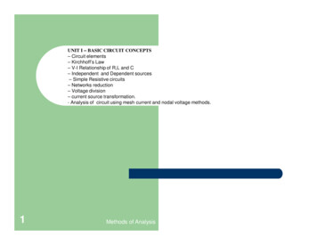
Simple Resonance - In AC circuits withthrough reactive components in parallelparallel RLC elements, damping describesresonant circuits can far exceed thethe amount of energy stored in a circuitvoltages and currents that are visiblecompared to that consumed. In a purelyacross the resistive elements. Q is alsoresistive circuit, the energy stored isthe ratio of center frequency to the –3 dBequal to zero. Reactive circuits (circuitsbandwidth.containing capacitors and/or inductors)can store energy during a transient to bedissipated later. Caution: The analysisbelow does not include parasitics andnon-optimum materials issues which oftenpredominate in a real-life circuit.Over damped -An overdamped circuit exhibits noringing, and takes excessive time toasymptotically approach the final value.Bandwidth - The bandwidth of a reactivecircuit is the difference between the twofrequencies where response changeswhereby 3 dB. Where DC is still full gain, itis the upper 3 dB point. Definition canbe dependent upon circuit topology,and whether current or voltage is themeasured parameter.Time Domain - The time domain responseof a circuit is calculated by writing theFrequency Domain - If we define resonantequation for the circuit, assuming somefrequency and quality factor (note thatinitial conditions and solving a differentialsince at resonance various shortcutsequation.Critically damped -A critically damped circuit approaches itsfinal value in the least possible time. Thismight be possible) thenoccurs whenwhich assumes the final form to bewhereResonant Frequency Use the quadratic equation to find theroots. Whether the discriminant showsis the resonant frequency inradians per second. It is defined by theinductance and capacitance withoutregard to resistance.Quality Factor -ortwo real roots, one root or two complexPassive Componentsroots decides the damping.A basic description of passiveVariables listed as An andaredetermined by initial conditions.Ohms Law -Under damped -vector sum of a resistive (positive x axis)the final value.this for series resonance.Fundamentally, it gives a clue as tothe amount of circulating energy in theresonant system that may not be visibleoutside the resonant system. Thusvoltages across reactive componentsin series resonant circuits, and currentsis thecomponents.Since 1/j is –j, capacitance uses thenegative y axis and inductance thepositive y axis in the imaginary planewhen summing impedance.Q defines the ratio of energy storedto energy dissipated during a cycle.wherecomponent and combined inductiveand capacitiveAn underdamped circuit generally ringsand may take excessive time to approachfor parallel resonance. It is the inverse ofcomponents.whereResistance/Conductance Resistance is that property of a conductorthat opposes the flow of current. It causesthe dissipation of real power. The diagramhere is used by covering the quantity to beidentified. What remains is the equationto calculate that quantity. E is calculated
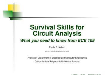
by multiplying I and R. I is calculated byCommutative -ABA*BA*B0001Capacitance - Capacitance is a measure0101of the propensity of parallel plates in a1001Associative -circuit to accumulate charge. No actual1110(A B) C A (B C)putting E over R.A*B B*ADC currents flow, but charges are addedto and taken from the parallel plates givingthe appearance of electron transfer as thevoltage changes.(A*B)*C A*(B*C)Or - The Or function outputs a oneTheorems - The following are useful andwhenever any input is one.orInductance - Inductance is a measure ofthe unwillingness of a circuit or componentto change current.A B B Aprovable from the postulates.Distributive -ABA BA B0001A*(B C) (A*B) (A*C)0110A (B*C) (A B)*(A C)1010DeMorgan’s Theorem -1110Invert - The invert function outputs a onewhenever its input is zero.Exponential Decay -AAComponents01Axial Leaded -10Xor/Xnor (exclusive or/nor) - The XorRadial Leaded -function outputs a one whenever oneand only one input is one. Xnor is thecomplement of Xor.Normal RL or RC time constants areexponential decays. The above showsthe remaining amplitude when t timeconstant τ.Digital LogicOperators - The standard Booleanoperators are described here. And, Or andInvert are fundamental. Nand, Nor, Xor andXnor are derived. Nand and Nor are easyin hardware. Xor and Xnor are useful inarithmetic circuits.Color CodesABABAB00010110101110Black 0Brown 1Red 2Orange 30Yellow 4Green 51Blue 6Purple 7Grey 8White 9Postulates - The following are two ofthe primary Boolean algebra postulates.Care should be taken with semanticshere. Boolean algebra, while similarto mathematic algebra in ways, is notidentical in its definitions. For example, theDistributive property of Boolean algebralisted here doesn’t match the distributiveproperty of mathematical algebra. It isAccuracy: None, 20% Silver 10%, Gold 5%Value (10*D1 D2)*10exponentIf exponent is Silver it is –2. If Gold –1.1% and better resistors use four colorbands for value.And/Nand - The And function outputs aimportant to keep in mind that the “ ” andInductors and Capacitors sometimes useone whenever all inputs are one. Nand is“ ” symbols have fundamentally differentcolor bands or dots to indicate value.the complement of And.meanings in Boolean and mathematic*algebra and therefore must be treateddifferently in some cases.
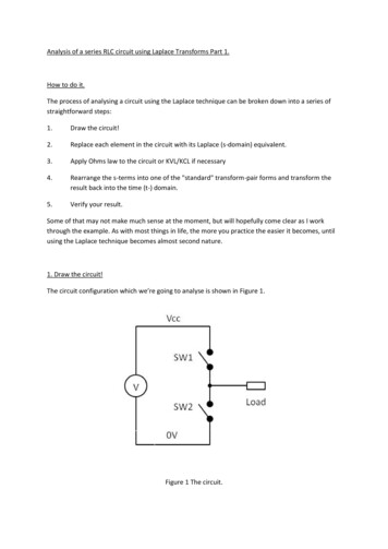
Standard Resistor ValuesNot every possible resistor value ispractically available. These are thestandard 5% values. 10% in bold. 20%in 291For information on precisionresistors check: tors and capacitors generally use thesame sequence. Often only the grayed boxvalues, however.Analysis TechniquesThe following covers some of the standardanalysis techniques, which depend on afew fundamental principles.Kirchoff’s Voltage Law - If you run aroundthe loop and sum up all the voltages,the sum must be 0 for a steady-statecondition. Depending which way you go,the source is positive and all the othersare negative. If these are Z’s rather thanR’s, then more care must be taken, but theresult is still correct.Kirchhoff’s Current Law - Similarly, ifProcedure:In particular, current sources are much1) Write down the node voltages forthose nodes on voltage sources.These are some of the equations.(x Vn1-Vn2 where x is the value of thevoltage source between N1 and N2)harder to make well than voltage sources.2) Short the voltage sources out. Thisreduces the node count since twopreviously unconnected nodes are nowtied together. Why does this work?Check source transformations.Where V IR or I V/R.3) Write the KCL equations for theremaining nodes, and expressthe currents as voltages acrossimpedances. There should now be N-1equations between those defined in 1and 3.regardless of the current. Thus the output4) Solve the equations. If the circuitincludes Ls and Cs, this requiresdifferential equations.and get the same current.Mesh Analysis - Mesh analysis is theIn any linear circuit with multiplecreation and solution of N-1 equations inindependent supplies, overall responseN-1 unknowns. (Why N-1? It takes twocan be calculated by calculating thenodes to build a mesh.)response for each supply individually, withProcedure:1) Write down the meshes. Label them.Assure the mesh is two dimensional.2) Write down the current sources.3) Open the current sources. See SourceTransformations for rationale.4) Write the equations for each remainingloop. Since there are only voltagesources and impedances left, thecurrents must be expressed in terms ofvolts and impedance.5) Solve the resulting equations. Again,if there are Ls and Cs, this requiresdifferential equations.you sum all the currents into (or out of) aThis works due to the definitions ofvoltage and current sources. A voltagesource maintains the same voltageimpedance is 0 (I1R I2R requires R 0).Similarly, the output impedance of acurrent source is infinite (or undefined)since you can put any voltage across itSuperpositionthe remaining supplies shorted for voltagesources, or open for current sources.TransformsThe following two transforms are criticalto electronics calculation. The LaplaceTransform provides a framework forfilter design and frequency responsecalculations. The Fourier Transform allowsyou to examine time domain waveformsin the frequency domain. Primarily used toidentify the transfer function of systems,these transforms are used somewhatinterchangeably. The Fourier Transformhas the advantage of being numericallySource Transformationscalculable under certain circumstances.There are two important reasons forLaplace Transform - The Laplacemore completely discussing sources.Transform creates a different dataNodal Analysis - Nodal analysis is theFirst, the analysis techniques suggestspace, often known as the s-domain, tocreation and solution of N-1 equations inunderstanding them better. Second,manipulate functions. These functions, inN-1 unknowns for a circuit with N nodes.you won’t always have the source youelectronics, represent realizable circuits.One node is defined as ground, so itneed, and it is important to be able toThe definition of the transform is:doesn’t need further solution. All the restcomfortably swap to something you have.node, the sum must be zero. Again, withnonresistive elements, care must be takenbut the result must hold.of the analysis is relative to that referenceground.
This transform makes dealing withwaveforms of various frequencies andso there can be many ways to representintegrals and derivatives quite simple,magnitudes. Non-repetitive waveformsthis equation. Applying Euler’s Identity towhich is why it is popular for analyzingrequire an infinite sum of sinusoids overFourier Transform expands it into a seriescircuits containing inductors anda continuous frequency band (henceof sine and cosine terms suggesting thecapacitors.the integral) to be described exactly.commonality with the Fourier series.Repetitive waveforms require an infiniteExample:sum of sinusoids at discrete frequencyintervals (hence the summation) to beexactly. While an infinite sum of sinusoidsdefines an exponential decay with theis required in either case to achieveequation:mathematical perfection, it is generallythe case that a limited set of the Fourierterms dominate the behavior of thewhereis the time constant of thewaveform.waveform, and it is often true that some ofthe terms are equal to zero. It is thereforepossible to make useful approximationsWhen transformed into the s-domain,by only considering the “relevant” Fouriercircuits are expressed in terms ofterms. The finite bandwidth of a systemzeroterms/pole-terms. The roots of theguarantees that some possible termsvarious equations provide the location ofwill be irrelevant since they are outsidethe –3 dB corners for the elements. Non-the passband. The Fourier Transform isreal roots can cause oscillatory behavior.defined as:common Laplace Transforms are availableThe Fourier Transform of an impulseon-line or in most texts covering theprovides constant amplitude stimulussubject.at all frequencies. Thus you can look atbasic descriptors of DSP operations.Euler’s Identity - Euler’s Identity shows theto be Fourier functions. Comparison ofthe definitions of H(s) and H () suggestthat they are very similar for all commonelectronic uses.Frequency Response(Bode Plot)The Bode plot takes the Laplace or Fourierbased transfer function, and graphicallyshows expected magnitude and phaseas a function of frequency. Zeros provideupwardly sloping lines with the inflectionpoint at the -3 dB frequency. Poles,downwardly.a dB vs log frequency plot and linearbased upon Laplace Tranforms. Tables ofinto z-domain equations, which are the) transfer functions are expectedThese can be graphically overlayed onThe common transfer function H(s) isS-domain equations are readily convertedH(phase vs log frequency plot to providea visualization of the overall transferfunction.the response and determine the transferLine slope is 20 dB/decade * thefunction.exponent of the pole or zero.A simplification for repetitive waveforms is20 dB/decade 6 dB/octave.of period 2π:relationship between polar and rectangularcoordinates in the imaginary plane:where:This identity is useful to keep in mindFind more valuable resources at TEK.COMwhen interpreting the formulas definingTektronix maintains a comprehensive, constantly expandingcollection of application notes, technical briefs and otherresources to help engineers working on the cutting edge oftechnology. Please visit tek.com.Fourier Analysis.Fourier Transform - The Fourier Transformis similar to the Laplace transform inoperation. However, unlike the LaplaceTransform, the Fourier Transform canbe implemented for repetitive signals.The Fourier Transform proves that anywaveform, no matter its shape, canbe described as a sum of sinusoidal–This later equation basically states that arepetitive waveform can be representedas the sum of a number of sine functionsThe sine and cosine terms effectivelycreate a single function at a phase shift,Copyright 2017, Tektronix. All rights reserved. Tektronixproducts are covered by U.S. and foreign patents, issued andpending. Information in this publication supersedes that in allpreviously published material. Specification and price changeprivileges reserved. TEKTRONIX and TEK are registeredtrademarks of Tektronix, Inc. All other trade names referencedare the service marks, trademarks or registered trademarks oftheir respective companies.02/17 EA xxx
Node - In a schematic or circuit, a point where multiple branches in the circuit join. A point where no voltage difference is possible. Branch - In a schematic or circuit, a chain of components with a single current path. Ground - 1) That portion of a circuit that can be tied to the earth or safety power connections without current being drawn. Or,